EP0707936B1 - Procédé pour déterminer le point de transition lors du moulage par injection d'un objet - Google Patents
Procédé pour déterminer le point de transition lors du moulage par injection d'un objet Download PDFInfo
- Publication number
- EP0707936B1 EP0707936B1 EP95810562A EP95810562A EP0707936B1 EP 0707936 B1 EP0707936 B1 EP 0707936B1 EP 95810562 A EP95810562 A EP 95810562A EP 95810562 A EP95810562 A EP 95810562A EP 0707936 B1 EP0707936 B1 EP 0707936B1
- Authority
- EP
- European Patent Office
- Prior art keywords
- classification
- variables
- derived
- function
- evaluation
- Prior art date
- Legal status (The legal status is an assumption and is not a legal conclusion. Google has not performed a legal analysis and makes no representation as to the accuracy of the status listed.)
- Expired - Lifetime
Links
Images


Classifications
-
- B—PERFORMING OPERATIONS; TRANSPORTING
- B29—WORKING OF PLASTICS; WORKING OF SUBSTANCES IN A PLASTIC STATE IN GENERAL
- B29C—SHAPING OR JOINING OF PLASTICS; SHAPING OF MATERIAL IN A PLASTIC STATE, NOT OTHERWISE PROVIDED FOR; AFTER-TREATMENT OF THE SHAPED PRODUCTS, e.g. REPAIRING
- B29C45/00—Injection moulding, i.e. forcing the required volume of moulding material through a nozzle into a closed mould; Apparatus therefor
- B29C45/17—Component parts, details or accessories; Auxiliary operations
- B29C45/76—Measuring, controlling or regulating
- B29C45/77—Measuring, controlling or regulating of velocity or pressure of moulding material
- B29C2045/776—Measuring, controlling or regulating of velocity or pressure of moulding material determining the switchover point to the holding pressure
Definitions
- the invention relates to a method for determining a Switchover point in the manufacture of an injection molded part according to the preamble of claim 1.
- injection molded parts be it from Plastic, metal or ceramic materials each plastic in a cavity of an injection mold Material using a suitable injection device injected, which then solidified by cooling or is cured. The mold is then opened and the injection molded part ejected.
- the injection device according to a Filling program is usually controlled so that the Delivery rate as a function of time certain setpoint specifications Fulfills.
- the Injection device during a holding phase usually regulated so that according to a reprint program the pressure in the cavity reaches certain setpoints that can also be time-dependent.
- the switch point i.e. H. the point in time at which the filling program changes to the Reprint program is switched, is determined correctly and coincides as exactly as possible with the time at which the cavity is just completely filled. It gets too early switched, there is a risk that the cavity to at this point is not completely filled and a uncontrolled filling takes place under pressure, from which a susceptible to warping under thermal stress Injection molded part results. If the switchover is too late, so too high a pressure is reached in the cavity and it results an injection molded part that is brittle and prone to breakage due to internal stress is.
- JP-A-05096591 describes the use of fuzzy "logic" for the Control and regulation proposed an injection molding machine without that however an internal pressure measurement in the cavity of the injection mold carried out and an exact determination of the switchover point is carried out.
- the regulation of the screw speed of an injection molding machine to a predetermined setpoint depending on the Screw position is the content of EP-A-0.264.453, without that here the cavity pressure is measured, or the methods of Fuzzy logic can be applied.
- EP-A-0.525.670 relates to an arrangement and a method of Fuzzy logic, regardless of the area of application. On the special Problem of determining the switchover point during injection molding therefore not received.
- the invention is therefore based on the object, a generic Procedure to indicate that the complete filling of the Cavity safely and timely, but against Faults due to random pressure fluctuations in the filling phase is stable.
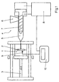
- the injection molding device of FIG. 1 has a shape 1 Metal, which encloses a cavity 2 in which the Injection molded part is molded.
- Form 1 is made from a z. B. hydraulic closing unit 3 closed and open.
- An injection device 4 is provided, which comprises an injection cylinder 5, on the upper side thereof a funnel 6 opens for the introduction of injection molding material and in which a screw 7 axially displaceable and is rotatably arranged. The movements of the screw 7 are determined by a controller 8.
- a pressure sensor 9 is arranged, which with a controller 10 is connected, which in turn with the Controller 8 is connected.
- the pressure sensor 9 could can also be arranged behind an ejector pin, in any case, it is located in cavity 2.
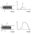
- the funnel 6 Injection molding compound usually in the form of granules, in the injection cylinder 5 introduced and by rapid rotation the screw 7 with simultaneous backward movement the same melted (Fig. 2a).
- the screw 7 In the cavity 2 of the mold 1 is no pressure in this first part of the filling phase built up (Fig. 2b).
- the ideal Switchover point U is changed from on to the filling program Reprint program switched, in which the Pressure curve in cavity 2 according to certain specifications is regulated.
- the pressure from the Pressure sensor 9 (Fig. 1) monitors and the measurement result the controller 10 forwarded, which in turn in the sense of Compliance with a predetermined target pressure on the control 8 acts, which the axial position of the worm 7th controls that are usually still light at this stage is advanced (Fig. 5a).
- the target pressure can be a Function of time (Fig. 5b), which after steep Rise falls back to the original value because the Injection molding compound cools and contracts.
- the determination of the switchover point between the filling phase and the holding pressure phase is of crucial importance for the quality of the injection molded part.
- the pressure in the cavity 2 is monitored by the pressure sensor 9 already in the filling phase and at regular intervals, for. B. every 10 msec, a measured value is transmitted to the controller 10.
- the current measured value p 0 is processed together with the measured values p -1 or p -2 taken 10 or 20 msec ago. After 10 msec, a new current measured value p 0 is determined in each case, while the previous current measured value p 0 becomes the measured value p -1 and this becomes the measured value p -2 .
- the algorithmic processing of the measured values p 0 , p -1 and p -2 takes place (FIG. 6) in a computing unit in the controller 10 according to the fuzzy logic methods in several stages.
- classification levels K 0 , K -1 and K -2 two classification variables are derived from each of the measured values p 0 , p -1 and p -2 (fuzzyfication) by using first and second classification functions k 0 + , k 0 - , k -1 + , k -1 - or k -2 + , k -2 - can be applied to the measured values p 0 , p -1 or p -2 .
- the first classification function k 0 + has the value 0 up to a lower limit pressure of 345 bar and then increases linearly until it reaches the value 1 at 1202 bar.
- the second classification function is complementary to the first, ie it adds up to a constant, in the present case 1.
- the first classification function k -1 + for the measured value p -1 corresponds qualitatively to the already described classification function k 0 + for the current measured value p 0 , only it rises from 375 bar and reaches the value 1 at 1175 bar.
- the second classification function k - 1 - is again complementary to the first.
- the classification functions k -2 + and k -2 - for the measured value p -2 correspond exactly to those for the measured value p -1 in the present case.
- the classification variables resulting from the evaluation of the classification functions k 0 + (p 0 ), k 0 - (p 0 ), k -1 + (p -1 ), k -1 - (p -1 ), k -2 + ( p -2 ) and k -2 - (p -2 ) are linked in a linkage level V (inference) and weighting variables g - , g 0 and g + derived from them.
- intermediate sizes are first produced by forming minima over subsets of the quantity of the classification sizes. T.
- G - max [0.5 min (k 0 + , k -1 - , k -2 - ), 0.2 min (k 0 - , k -1 + , k -2 + ), 0.2 min (k 0 - , k -1 + , k -2 - )]
- G 0 max [0.5 min (k 0 + , k -1 + , k -2 - ), 0.5 min (k 0 + , k -1 - , k -2 - ), 0.2 min (k 0 - , k -1 + , k -2 - ), 0.6 min (k 0 - , k -1 - , k -2 + )]
- G + max [1.0 min (k 0 - , k -1 + ,
- each of the minima that lead to an intermediate variable is formed by a triple of classification variables, which is in each case composed of classification variables derived from the different measured values p 0 , p -1 and p -2 .
- classification variables k 0 + , k 0 - derived from the current measured value p 0 always occurs as an argument.
- a real switching value s in the present case between 0 and 1, is now derived from the weighting variables g - , g 0 and g + (defuzzification).
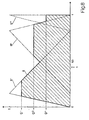
- the weighting variables g - , g 0 and g + are linked to fixed evaluation functions a - , a 0 and a + (FIG. 8).
- the graphs of the evaluation functions have surface centroids that are clearly offset from each other in the x direction, ie the median, corresponding to the x component of the surface centroid, is significantly larger at a + than at a ° and significantly larger at a ° than at a - .
- the carriers of the functions are also shifted accordingly, although they overlap widely.
- the evaluation functions are very simple in the present case. They all increase linearly from 0 to 1 and then also decrease linearly from 1 to 0.
- the linking of the weighting quantity g + with the evaluation function a + to a modified evaluation function takes place simply by cutting off the latter at the value of the weighting quantity g + , ie the minimum of the evaluation function a + and a constant function with the value g + is formed.
- the evaluation functions a 0 and a - are carried out analogously. From the evaluation functions modified in this way, a switching function a is finally formed by maximum formation, the graph of which consequently corresponds to the union of the graphs of the modified evaluation functions.
- the median is now used to determine the switching value s Switching function s according to the x component of your Center of gravity formed. It is obvious that every evaluation function the switching value all the more in the sense a shift against their own median, the larger the assigned weight size is.
- the switching value s is below a threshold value of 0.5, then is finally in a decision stage E (Fig. 6) derived that the switchover point has not yet been reached. If, on the other hand, the switching value exceeds the threshold, see above is derived from the fact that the switchover point is reached and switched to the reprint program.
Landscapes
- Engineering & Computer Science (AREA)
- Manufacturing & Machinery (AREA)
- Mechanical Engineering (AREA)
- Injection Moulding Of Plastics Or The Like (AREA)
- Moulds For Moulding Plastics Or The Like (AREA)
Claims (20)
- Procédés pour la détermination du point de commutation (u) lors de la fabrication d'une pièce injectée, au cours duquel un dispositif d'injection (4) remplit une cavité (2) d'un moule (1) jusqu'au point de commutation (u) selon un programme de remplissage et une évolution de pression est engendrée, conformément à un programme de maintien de pression, après le point de commutation (u) en effectuant plusieurs mesures successives de la pression à l'intérieur de la cavité (2) et après chaque mesure il est détérminé par un traitement algorithmique de la valeur de mesure actuelle (po) et des valeurs de mesure antérieures (p-1, p-2) dans un calculateur si le point de commutation (u) est atteint ou pas,
caractérisés en ce que le traitement algorithmique des valeurs de mesure (po, p1, p2) s'effectue par convexion fonctionnel des grandeurs de classification [ko + (po), ko - (po), k-1 + (p-1), k-1 -(p1), k-2 + (p-2), k-2 - (p-2)] déduites respectivement d'un étage de classification (ko, k-1, k-2) selon des méthodes de la logique floue. - Procédés selon revendication 1 caractérisés en ce qu'à partir d'une valeur de mesure (po, p-1, p-2) une première grandeur de classification est déterminée [ko + (po), k-1 + (p-1), k-2 + (p-2)] en traitant cette valeur dans une première fonction de classification (ko +, k-1 +, k-2 +).
- Procédés selon revendication 2 caractérisés en ce que la première
fonction de classification (ko +, k-1 +, k-2 +) a une valeur constante pour les faibles valeurs de pression et augmente dans un intervalle débutant à une pression-limite inférieure positive. - Procédés selon revendications 2 ou 3 caractérisés en ce qu'une deuxième grandeur de classification [ko - (po), k-1 - (p-1), k-2 - (p-2)] est déduite d'une valeur de mesure (po, p-1, p-2) en traitant cette valeur dans une deuxième fonction de classification (ko -, k-1 -, k-2 -).
- Procédés selon revendication 3 et 4 caractérisés en ce que la deuxième fonction de classification (ko -, k-1 -, k-2 -) est respectivement complémentaire de la première fonction de classification (ko +, k-1 +, k-2 +).
- Procédés selon l'une des revendications 3 à 5 caractérisés en ce que la pression-limite inférieure se situe, selon le cas, entre 300 et 450 bar.
- Procédés selon l'une des revendications 3 à 6 caractérisés en ce que pour la première fonction de classification utilisée pour traiter la valeur de mesure actuelle (po) la pression-limite inférieure est plus basse que pour les autres premières fonctions de classification (k-1 +, k-2 +).
- Procédés selon l'une des revendications 2 à 7 caractérisés en ce que au moins deux grandeurs de pondération (g-, go, g+) sont déterminées à partir des grandeurs de classification [ko + (po), ko - (po), k-1 + (p-1), k-1 - (p-1), k-2 + (p-2), k-2 - (p-2)] dans un étage de couplage v.
- Procédés selon revendication 8 caractérisés en ce que, dans l'étage de couplage (v), trois grandeurs de pondération (g-, go, g+) sont déduites des grandeurs de classification [ko + (po), ko - (po), k-1 + (p-1), k-1 - (p-1), k-2 + (p-2), k-2 - (p-2)].
- Procédés selon revendication 8 ou 9 caractérisés en ce que dans l'étage de couplage, des grandeurs intermédiaires sont créées par formation de minimas par des quantités partielles de la quantité des grandeurs de classification [ko + (po), ko - (po), k-1 + (p-1), k-1 - (p-1), k-2 + (p-2), k-2 - (p-2)] à partir desquelles les grandeurs de pondération (g-, go, g+) peuvent être déduites.
- Procédés selon revendication 10 caractérisés en ce que les quantités partielles de grandeurs de classification à partir desquelles un minima est formé, contiennent au moins une des grandeurs de classification [ko + (po), ko - (po)] déduite de la valeur de mesure actuelle (po).
- Procédés selon revendication 10 ou 11 caractérisés en ce que le couplage des grandeurs intermédiaires relatives aux grandeurs de pondération (g-, go, g+) s'effectue par formation de maxima à partir de quantités partielles de la quantité des grandeurs intermédiaires après une graduation occasionnelle de ces dernières.
- Procédés selon revendication 8 à 12 caractérisés en ce que, dans un étage de traitement (A), une valeur de commutation (s) est formée à partir des grandeurs de pondération (g-, go, g+), valeur à partir de laquelle il est déduit si le point de commutation (u) est atteint ou non.
- Procédés selon revendication 13 caractérisés en ce que dans l'étage de traitement (A) une fonction de traitement modifiée est selon le cas déduite d'une grandeur de pondération (g-, go, g+) et d'une fonction de traitement modifiée (a-, ao, a+) qui lui est attribuée, les fonctions de traitement attribuées à différentes grandeurs de pondération étant différentes entre elles, fonction qui, pour le même vecteur, croit avec la grandeur de pondération (g-, go, g+) et que finalement, une fonction de commutation (a) est obtenue comme maxima des fonctions de traitement modifiées à partir de laquelle la valeur de commutation (s) est déduite.
- Procédés selon revendication 14 caractérisés en ce que les fonctions de traitement (a-, ao, a+) se différencient par leurs points médians et que la valeur de commutation (s) est formée par formation du point médian de la fonction de commutation (a).
- Procédés selon revendication 14 ou 15 caractérisés en ce que la fonction de traitement modifiée est considérée comme minima de la fonction de traitement (a-, ao, a+) et celui de la fonction de pondération (g-, go, g+) considéré comme fonction constante correspondante.
- Procédés selon l'une des revendications 13 à 16 caractérisés en ce qu'à partir de la valeur de commutation (s) il peut être exactement déduit que le point de commutation (u) est atteint lorsque ce dernier dépasse une valeur de seuil.
- Procédés selon l'une des revendications 1 à 17 caractérisés en ce que pour déterminer si le point de commutation (u) est atteint ou pas, non seulement la valeur de mesure actuelle (po) mais aussi les deux dernières valeurs de mesure relevées (p-1, p-2) sont prises en considération.
- Procédés selon l'une des revendications 1 à 18 caractérisés en ce que les valeurs de mesure sont relevées à des intervalles de temps réguliers.
- Procédés selon l'une des revendications 1 à 19 caractérisés en ce que l'intervalle de temps entre deux mesures consécutives ne dépasse pas 20 msec.
Applications Claiming Priority (3)
| Application Number | Priority Date | Filing Date | Title |
|---|---|---|---|
| CH3135/94 | 1994-10-19 | ||
| CH03135/94A CH688441A5 (de) | 1994-10-19 | 1994-10-19 | Verfahren zur Bestimmung des Umschaltpunktes bei der Herstellung eines Spritzgussteils. |
| CH313594 | 1994-10-19 |
Publications (3)
| Publication Number | Publication Date |
|---|---|
| EP0707936A2 EP0707936A2 (fr) | 1996-04-24 |
| EP0707936A3 EP0707936A3 (fr) | 1998-02-04 |
| EP0707936B1 true EP0707936B1 (fr) | 2001-11-14 |
Family
ID=4249379
Family Applications (1)
| Application Number | Title | Priority Date | Filing Date |
|---|---|---|---|
| EP95810562A Expired - Lifetime EP0707936B1 (fr) | 1994-10-19 | 1995-09-11 | Procédé pour déterminer le point de transition lors du moulage par injection d'un objet |
Country Status (4)
| Country | Link |
|---|---|
| US (1) | US5665283A (fr) |
| EP (1) | EP0707936B1 (fr) |
| CH (1) | CH688441A5 (fr) |
| DE (1) | DE59509839D1 (fr) |
Families Citing this family (17)
| Publication number | Priority date | Publication date | Assignee | Title |
|---|---|---|---|---|
| DE19536566C1 (de) * | 1995-10-02 | 1997-02-06 | Arburg Gmbh & Co | Verfahren zur Regelung des Werkzeuginnendrucks an einer zyklisch arbeitenden Maschine |
| CH692491A5 (de) * | 1997-04-23 | 2002-07-15 | Kk Holding Ag | Verfahren zur Bestimmung des Umschlaltpunktes bei der Herstellung eines Spritzgussteils. |
| ATE320904T1 (de) * | 1997-08-21 | 2006-04-15 | Kistler Holding Ag | Verfahren zum regeln einer spritzgiessanlage für kunststoff-materialien |
| CH692383A5 (de) * | 1997-09-16 | 2002-05-31 | Kk Holding Ag | Verfahren zur Regelung der Heisskanalheizung eines Mehrkavitäten-Spritzgiesswerkzeugs. |
| US6309571B2 (en) * | 1998-02-27 | 2001-10-30 | The Hong Kong University Of Science & Technology | Method and apparatus for the control of injection molding |
| AU2002235156A1 (en) | 2000-11-06 | 2002-05-15 | Frederick J. Buja | Method and apparatus for controlling a mold melt-flow process using temperature sensors |
| FR2829960B1 (fr) * | 2001-09-21 | 2006-10-27 | Jean Pierre Lesbats | Procede de parametrage d'un dispositif d'injection de moulage et dispositif pour sa mise en oeuvre |
| US7182893B2 (en) | 2002-10-11 | 2007-02-27 | Mold-Masters Limited | Valve gated nozzle having a valve pin with a sensor |
| CA2463498C (fr) | 2001-10-12 | 2012-04-24 | Mold-Masters Limited | Tige de soupape a thermocouple |
| DE102004051109B4 (de) * | 2004-10-19 | 2007-01-18 | Siemens Ag | Verfahren zum Betrieb einer Spritzgießmaschine |
| US7585166B2 (en) * | 2005-05-02 | 2009-09-08 | Buja Frederick J | System for monitoring temperature and pressure during a molding process |
| US8790256B2 (en) | 2006-08-14 | 2014-07-29 | Frederick J. Buja | System and method employing a thermocouple junction for monitoring of physiological parameters |
| US20080085334A1 (en) * | 2006-10-10 | 2008-04-10 | Husky Injection Molding Systems Ltd. | Hot Runner System Sensor |
| DE102008038930A1 (de) | 2008-08-13 | 2010-02-18 | Priamus System Technologies Ag | Verfahren zum Regeln bzw. Steuern von Funktionen einer Spritzgiessmaschine |
| US8986205B2 (en) | 2010-05-14 | 2015-03-24 | Frederick J. Buja | Sensor for measurement of temperature and pressure for a cyclic process |
| AU2014296127A1 (en) | 2013-08-01 | 2016-02-18 | iMFLUX Inc. | Injection molding machines and methods for accounting for changes in material properties during injection molding runs |
| RU2016102962A (ru) | 2013-08-01 | 2017-09-04 | ИМФЛЮКС Инк. | Устройства и способы литья под давлением, учитывающие изменения свойств материала во время процесса литья под давлением |
Family Cites Families (11)
| Publication number | Priority date | Publication date | Assignee | Title |
|---|---|---|---|---|
| GB1549771A (en) * | 1975-07-11 | 1979-08-08 | Post Office | Vibratory tool with vibration isolation mechanism |
| JPS62218120A (ja) * | 1986-03-20 | 1987-09-25 | Fanuc Ltd | 射出速度の加減速時間が変更できる射出成形機 |
| JPH0497816A (ja) * | 1990-08-16 | 1992-03-30 | Omron Corp | 成形機のコントローラ |
| JPH04119814A (ja) * | 1990-09-10 | 1992-04-21 | Nissei Plastics Ind Co | 射出成形機の温度制御方法 |
| DE4041229A1 (de) * | 1990-12-18 | 1992-06-25 | Automatisierungs Und Kunststof | Verfahren zur regelung und steuerung des spritzgiessens |
| JPH0535308A (ja) * | 1991-07-25 | 1993-02-12 | Mitsubishi Electric Corp | フアジイメンバシツプ関数の同定装置及び同定方法 |
| DE59107090D1 (de) * | 1991-10-01 | 1996-01-25 | Mannesmann Ag | Verfahren zur Trendregelung des Umschaltpunktes beim Spritzgiessen |
| JPH0596591A (ja) * | 1991-10-11 | 1993-04-20 | Sumitomo Heavy Ind Ltd | 射出成形機の制御装置 |
| DE4140392C2 (de) | 1991-12-07 | 1997-02-20 | Bosch Gmbh Robert | Verfahren zur Regelung eines Spritzgießprozesses |
| JP2779759B2 (ja) * | 1993-12-15 | 1998-07-23 | 日精樹脂工業株式会社 | 射出成形機の射出制御方法 |
| JPH07304079A (ja) * | 1994-05-10 | 1995-11-21 | Sodick Co Ltd | 射出成形機の制御装置 |
-
1994
- 1994-10-19 CH CH03135/94A patent/CH688441A5/de not_active IP Right Cessation
-
1995
- 1995-09-11 EP EP95810562A patent/EP0707936B1/fr not_active Expired - Lifetime
- 1995-09-11 DE DE59509839T patent/DE59509839D1/de not_active Expired - Lifetime
- 1995-09-18 US US08/529,536 patent/US5665283A/en not_active Expired - Fee Related
Also Published As
| Publication number | Publication date |
|---|---|
| DE59509839D1 (de) | 2001-12-20 |
| CH688441A5 (de) | 1997-09-30 |
| US5665283A (en) | 1997-09-09 |
| EP0707936A2 (fr) | 1996-04-24 |
| EP0707936A3 (fr) | 1998-02-04 |
Similar Documents
| Publication | Publication Date | Title |
|---|---|---|
| EP0707936B1 (fr) | Procédé pour déterminer le point de transition lors du moulage par injection d'un objet | |
| DE69637088T2 (de) | Verfahren und Vorrichtung zum Spritzgiessen von Leichtmetall | |
| DE4446857B4 (de) | Verfahren zur automatischen Einstellung einer Spritzgußgeschwindigkeitsbedingung in einer Spritzgußmaschine | |
| EP0897786B1 (fr) | Procédé de régulation d'une machine de moulage par injection de matières plastiques | |
| DE69113128T2 (de) | Spritzgusssteuerung mit veränderbar geregeltem Lernverfahren. | |
| EP0909628A2 (fr) | Méthode et dispositif pour le réglage du chauffage du canal d'injection d'un moule à cavités multiples | |
| DE69125645T2 (de) | Spritzgiesssteuereinrichtung mit wählbaren Kontrollfunktionen | |
| DE2207001A1 (de) | Spritzgußvorrichtung und -verfahren für synthetisches Harz | |
| DE69113869T2 (de) | Spritzgiesssteuerung mit prozessvariablem Lernverfahren. | |
| DE69617974T2 (de) | Kombinationssteuerung für das spritzgiessen | |
| DE68914837T2 (de) | Düsenberührungsanordnung für eine einspritzgiessmaschine. | |
| CH692491A5 (de) | Verfahren zur Bestimmung des Umschlaltpunktes bei der Herstellung eines Spritzgussteils. | |
| EP1056583B1 (fr) | Procede pour evaluer des pieces moulees | |
| WO2002076704A1 (fr) | Procede pour la regulation du retrait de pieces moulees par injection | |
| DE4002398C2 (de) | Vorrichtung zum Steuern der Einregelung der Gießbedingungen einer Spritzgießmaschine | |
| DE3586151T2 (de) | Verfahren zum spritzgiessen fuer geschmolzenen kunststoff. | |
| DE69718641T2 (de) | Verfahren und system zum spritzgiessen von kunststoffen und von thermoplastischen elastomeren | |
| DE69918402T2 (de) | Verfahren zur Regelung der Spritzphase bei einer Spritzgiessmaschine | |
| EP3698937B1 (fr) | Procédé pour régler le remplissage d'au moins une cavité | |
| DE3809792A1 (de) | Verfahren und vorrichtung zum spritzgiessen | |
| WO2010040463A1 (fr) | Procédé de moulage par injection et installation associée | |
| DE102004051109B4 (de) | Verfahren zum Betrieb einer Spritzgießmaschine | |
| EP0993923A2 (fr) | Procédé pour fabriquer des objets techniques moulés telle que des semelles de chaussures mono-couche ou multi-couche en caoutchouc ou matière thermoplastique et appareil pour sa mise en oeuvre | |
| DE10309871B4 (de) | Verfahren zum Spritzgiessen | |
| DE102020003905A1 (de) | Spritzgießmaschine |
Legal Events
| Date | Code | Title | Description |
|---|---|---|---|
| PUAI | Public reference made under article 153(3) epc to a published international application that has entered the european phase |
Free format text: ORIGINAL CODE: 0009012 |
|
| AK | Designated contracting states |
Kind code of ref document: A2 Designated state(s): DE FR GB |
|
| PUAL | Search report despatched |
Free format text: ORIGINAL CODE: 0009013 |
|
| AK | Designated contracting states |
Kind code of ref document: A3 Designated state(s): DE FR GB |
|
| 17P | Request for examination filed |
Effective date: 19980714 |
|
| 17Q | First examination report despatched |
Effective date: 20000613 |
|
| GRAG | Despatch of communication of intention to grant |
Free format text: ORIGINAL CODE: EPIDOS AGRA |
|
| GRAG | Despatch of communication of intention to grant |
Free format text: ORIGINAL CODE: EPIDOS AGRA |
|
| GRAH | Despatch of communication of intention to grant a patent |
Free format text: ORIGINAL CODE: EPIDOS IGRA |
|
| GRAH | Despatch of communication of intention to grant a patent |
Free format text: ORIGINAL CODE: EPIDOS IGRA |
|
| GRAA | (expected) grant |
Free format text: ORIGINAL CODE: 0009210 |
|
| RIN1 | Information on inventor provided before grant (corrected) |
Inventor name: GRECO, LUIGI Inventor name: BADER, CHRISTOPHERUS |
|
| AK | Designated contracting states |
Kind code of ref document: B1 Designated state(s): DE FR GB |
|
| REF | Corresponds to: |
Ref document number: 59509839 Country of ref document: DE Date of ref document: 20011220 |
|
| REG | Reference to a national code |
Ref country code: GB Ref legal event code: IF02 |
|
| GBT | Gb: translation of ep patent filed (gb section 77(6)(a)/1977) |
Effective date: 20020208 |
|
| PLBE | No opposition filed within time limit |
Free format text: ORIGINAL CODE: 0009261 |
|
| STAA | Information on the status of an ep patent application or granted ep patent |
Free format text: STATUS: NO OPPOSITION FILED WITHIN TIME LIMIT |
|
| 26N | No opposition filed | ||
| PGFP | Annual fee paid to national office [announced via postgrant information from national office to epo] |
Ref country code: DE Payment date: 20130919 Year of fee payment: 19 |
|
| PGFP | Annual fee paid to national office [announced via postgrant information from national office to epo] |
Ref country code: FR Payment date: 20130919 Year of fee payment: 19 Ref country code: GB Payment date: 20130919 Year of fee payment: 19 |
|
| REG | Reference to a national code |
Ref country code: DE Ref legal event code: R119 Ref document number: 59509839 Country of ref document: DE |
|
| GBPC | Gb: european patent ceased through non-payment of renewal fee |
Effective date: 20140911 |
|
| REG | Reference to a national code |
Ref country code: DE Ref legal event code: R119 Ref document number: 59509839 Country of ref document: DE Effective date: 20150401 |
|
| REG | Reference to a national code |
Ref country code: FR Ref legal event code: ST Effective date: 20150529 |
|
| PG25 | Lapsed in a contracting state [announced via postgrant information from national office to epo] |
Ref country code: GB Free format text: LAPSE BECAUSE OF NON-PAYMENT OF DUE FEES Effective date: 20140911 Ref country code: DE Free format text: LAPSE BECAUSE OF NON-PAYMENT OF DUE FEES Effective date: 20150401 |
|
| PG25 | Lapsed in a contracting state [announced via postgrant information from national office to epo] |
Ref country code: FR Free format text: LAPSE BECAUSE OF NON-PAYMENT OF DUE FEES Effective date: 20140930 |