EP0708185B1 - Appareil pour traiter la surface d'un objet, notamment la surface interne des réservoirs de carburant - Google Patents
Appareil pour traiter la surface d'un objet, notamment la surface interne des réservoirs de carburant Download PDFInfo
- Publication number
- EP0708185B1 EP0708185B1 EP95115988A EP95115988A EP0708185B1 EP 0708185 B1 EP0708185 B1 EP 0708185B1 EP 95115988 A EP95115988 A EP 95115988A EP 95115988 A EP95115988 A EP 95115988A EP 0708185 B1 EP0708185 B1 EP 0708185B1
- Authority
- EP
- European Patent Office
- Prior art keywords
- hollow body
- shell
- line
- recesses
- vacuum
- Prior art date
- Legal status (The legal status is an assumption and is not a legal conclusion. Google has not performed a legal analysis and makes no representation as to the accuracy of the status listed.)
- Expired - Lifetime
Links
- 239000002828 fuel tank Substances 0.000 title claims description 8
- 239000007789 gas Substances 0.000 claims description 27
- 238000000034 method Methods 0.000 claims description 11
- 239000001307 helium Substances 0.000 claims description 9
- 229910052734 helium Inorganic materials 0.000 claims description 9
- SWQJXJOGLNCZEY-UHFFFAOYSA-N helium atom Chemical compound [He] SWQJXJOGLNCZEY-UHFFFAOYSA-N 0.000 claims description 9
- 239000002184 metal Substances 0.000 claims description 8
- VYPSYNLAJGMNEJ-UHFFFAOYSA-N Silicium dioxide Chemical compound O=[Si]=O VYPSYNLAJGMNEJ-UHFFFAOYSA-N 0.000 claims description 2
- 238000007789 sealing Methods 0.000 claims 1
- 238000000926 separation method Methods 0.000 claims 1
- 230000001550 time effect Effects 0.000 claims 1
- 239000011248 coating agent Substances 0.000 description 10
- 238000000576 coating method Methods 0.000 description 10
- 239000004033 plastic Substances 0.000 description 5
- 239000012495 reaction gas Substances 0.000 description 5
- 230000002401 inhibitory effect Effects 0.000 description 4
- 238000009423 ventilation Methods 0.000 description 4
- 230000004888 barrier function Effects 0.000 description 3
- 230000000694 effects Effects 0.000 description 3
- 239000004615 ingredient Substances 0.000 description 3
- 239000004020 conductor Substances 0.000 description 2
- 230000005284 excitation Effects 0.000 description 2
- 239000000203 mixture Substances 0.000 description 2
- 238000005086 pumping Methods 0.000 description 2
- 239000000523 sample Substances 0.000 description 2
- PXGOKWXKJXAPGV-UHFFFAOYSA-N Fluorine Chemical compound FF PXGOKWXKJXAPGV-UHFFFAOYSA-N 0.000 description 1
- UFHFLCQGNIYNRP-UHFFFAOYSA-N Hydrogen Chemical compound [H][H] UFHFLCQGNIYNRP-UHFFFAOYSA-N 0.000 description 1
- 229910018503 SF6 Inorganic materials 0.000 description 1
- 230000000903 blocking effect Effects 0.000 description 1
- 239000012611 container material Substances 0.000 description 1
- 230000008021 deposition Effects 0.000 description 1
- 239000003989 dielectric material Substances 0.000 description 1
- 238000000605 extraction Methods 0.000 description 1
- 239000000945 filler Substances 0.000 description 1
- 238000003682 fluorination reaction Methods 0.000 description 1
- 229910052731 fluorine Inorganic materials 0.000 description 1
- 239000011737 fluorine Substances 0.000 description 1
- 239000003205 fragrance Substances 0.000 description 1
- 239000003365 glass fiber Substances 0.000 description 1
- 239000000383 hazardous chemical Substances 0.000 description 1
- 239000001257 hydrogen Substances 0.000 description 1
- 229910052739 hydrogen Inorganic materials 0.000 description 1
- 238000007373 indentation Methods 0.000 description 1
- 238000003780 insertion Methods 0.000 description 1
- 230000037431 insertion Effects 0.000 description 1
- 239000007788 liquid Substances 0.000 description 1
- 238000004519 manufacturing process Methods 0.000 description 1
- 239000000463 material Substances 0.000 description 1
- 239000002245 particle Substances 0.000 description 1
- 238000006116 polymerization reaction Methods 0.000 description 1
- 238000003908 quality control method Methods 0.000 description 1
- 239000010453 quartz Substances 0.000 description 1
- 230000005855 radiation Effects 0.000 description 1
- 230000000087 stabilizing effect Effects 0.000 description 1
- SFZCNBIFKDRMGX-UHFFFAOYSA-N sulfur hexafluoride Chemical compound FS(F)(F)(F)(F)F SFZCNBIFKDRMGX-UHFFFAOYSA-N 0.000 description 1
- 229960000909 sulfur hexafluoride Drugs 0.000 description 1
Images

Classifications
-
- B—PERFORMING OPERATIONS; TRANSPORTING
- B05—SPRAYING OR ATOMISING IN GENERAL; APPLYING FLUENT MATERIALS TO SURFACES, IN GENERAL
- B05D—PROCESSES FOR APPLYING FLUENT MATERIALS TO SURFACES, IN GENERAL
- B05D1/00—Processes for applying liquids or other fluent materials
- B05D1/62—Plasma-deposition of organic layers
-
- B—PERFORMING OPERATIONS; TRANSPORTING
- B05—SPRAYING OR ATOMISING IN GENERAL; APPLYING FLUENT MATERIALS TO SURFACES, IN GENERAL
- B05D—PROCESSES FOR APPLYING FLUENT MATERIALS TO SURFACES, IN GENERAL
- B05D7/00—Processes, other than flocking, specially adapted for applying liquids or other fluent materials to particular surfaces or for applying particular liquids or other fluent materials
- B05D7/22—Processes, other than flocking, specially adapted for applying liquids or other fluent materials to particular surfaces or for applying particular liquids or other fluent materials to internal surfaces, e.g. of tubes
- B05D7/227—Processes, other than flocking, specially adapted for applying liquids or other fluent materials to particular surfaces or for applying particular liquids or other fluent materials to internal surfaces, e.g. of tubes of containers, cans or the like
-
- B—PERFORMING OPERATIONS; TRANSPORTING
- B29—WORKING OF PLASTICS; WORKING OF SUBSTANCES IN A PLASTIC STATE IN GENERAL
- B29C—SHAPING OR JOINING OF PLASTICS; SHAPING OF MATERIAL IN A PLASTIC STATE, NOT OTHERWISE PROVIDED FOR; AFTER-TREATMENT OF THE SHAPED PRODUCTS, e.g. REPAIRING
- B29C59/00—Surface shaping of articles, e.g. embossing; Apparatus therefor
- B29C59/14—Surface shaping of articles, e.g. embossing; Apparatus therefor by plasma treatment
- B29C59/142—Surface shaping of articles, e.g. embossing; Apparatus therefor by plasma treatment of profiled articles, e.g. hollow or tubular articles
-
- B—PERFORMING OPERATIONS; TRANSPORTING
- B60—VEHICLES IN GENERAL
- B60K—ARRANGEMENT OR MOUNTING OF PROPULSION UNITS OR OF TRANSMISSIONS IN VEHICLES; ARRANGEMENT OR MOUNTING OF PLURAL DIVERSE PRIME-MOVERS IN VEHICLES; AUXILIARY DRIVES FOR VEHICLES; INSTRUMENTATION OR DASHBOARDS FOR VEHICLES; ARRANGEMENTS IN CONNECTION WITH COOLING, AIR INTAKE, GAS EXHAUST OR FUEL SUPPLY OF PROPULSION UNITS IN VEHICLES
- B60K15/00—Arrangement in connection with fuel supply of combustion engines or other fuel consuming energy converters, e.g. fuel cells; Mounting or construction of fuel tanks
- B60K15/03—Fuel tanks
- B60K15/03177—Fuel tanks made of non-metallic material, e.g. plastics, or of a combination of non-metallic and metallic material
-
- H—ELECTRICITY
- H05—ELECTRIC TECHNIQUES NOT OTHERWISE PROVIDED FOR
- H05H—PLASMA TECHNIQUE; PRODUCTION OF ACCELERATED ELECTRICALLY-CHARGED PARTICLES OR OF NEUTRONS; PRODUCTION OR ACCELERATION OF NEUTRAL MOLECULAR OR ATOMIC BEAMS
- H05H1/00—Generating plasma; Handling plasma
- H05H1/24—Generating plasma
- H05H1/46—Generating plasma using applied electromagnetic fields, e.g. high frequency or microwave energy
Definitions
- the invention relates to a device for treating surfaces of hollow bodies, in particular of inner surfaces of fuel tanks, with a treatment chamber evacuable via vacuum pumps, one the Hollow body in the treatment chamber supporting bracket, with a Line for the admission of a process gas into the treatment chamber and with a microwave conductor connected to a generator for ignition of a plasma in the area of the hollow body.
- a particularly promising process for generating suitable Barrier layers are plasma polymerisation, since this very thin plastic layers also inside the container let it separate. This is in addition to the required blocking effect good recyclability of the container material.
- a special The advantage over the currently used fluorination process is that The fact that no hazardous substances (such as fluorine) are used have to.
- a method for the plasma interior coating of hollow bodies is known (DE 36 32 748) in which microwaves for generating the plasma be fed into the outside of the tank so that a homogeneous microwave field is generated inside the plasma reactor.
- microwaves for generating the plasma be fed into the outside of the tank so that a homogeneous microwave field is generated inside the plasma reactor.
- JP 3 107 458 a method for coating the inside of plastic tanks is known (JP 3 107 458), in which two are introduced into the tank with the aid of one High frequency voltage applied to a plasma within the electrodes Tanks produced and for a pretreatment and a subsequent polymerization is used.
- the common disadvantage of the devices mentioned is that they do not Offer opportunities to create a plasma with a homogeneous coating effect achieve and also no quick control of the layer quality, in particular allow their permeation barrier effect.
- This disadvantage weighs all the more heavier than the permitted permeation of ingredients from the container in the case of fuel tanks is getting lower, on the other hand the Time required for their determination in specially built test chambers is in the range of months.
- the invention has for its object to provide a device the most homogeneous distribution of the excitation energy for the Plasma allows, which is an essential condition for the deposition a layer with uniform properties, e.g. Fat, realized is, the device should also enable the tightness every coated container with little expenditure of time and money to consider. In addition, the device should be in the sense of "just in time” production with the lowest possible set-up effort for coating different Container shapes can be used.
- this object is achieved by a configuration of the hollow body provided with a filling opening, this enveloping sheet metal shell, groove-shaped depressions in the sheet metal shell are incorporated or embossed together with the one covering them Hollow body wall form a waveguide with the generator can be connected via the microwave conductor, the line for the process gas is insertable into the interior of the hollow body and wherein a closure part or plug is provided, through which the filler opening of the Hollow body can be closed in a pressure-tight manner.
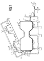
- the invention allows a wide variety of design options, one of which is shown schematically in more detail in the attached drawings, which the device in longitudinal section both in the closed and open Show condition.
- a hinged vacuum chamber 1 is lined with at least two shell-shaped sheets 2, 2 ', such that a cavity 3 enclosed by both sheets has essentially the same configuration as the fuel tank 4 to be coated.
- plugs 7, 7' for quickly closing the various openings 6, 6 'of the container 4, which are preferably designed such that the openings 6, 6' are when they are folded the vacuum chamber 1 automatically, for example by closing the pressure, thus separating the interior of the container 4 from the interior of the vacuum chamber 1.
- at least one of the closures or plugs 7, 7' is designed such that it allows the supply and extraction of reaction gas at the same time, the corresponding vacuum line 8 and gas supply line 9 or 9 'being no connection for the interior of the vacuum chamber 1.
- the vacuum chamber 1 is in turn connected to a vacuum pumping station 13 and a ventilation valve 14 via a separate vacuum line 10.
- the reaction gas or reaction gas mixture is removed from one or more gas or liquid containers 11 and 11 'and fed to the container interior 3 via a line 12, 12'.
- At least one control valve 15, 15 ' is provided within the line for metering the reaction gas stream.
- the gas supply line 9, 9 ' is connected via a valve 16 to a supply line for helium 24 and the vacuum line 8 via a valve 17 to a helium detector 18.
- the microwave supply takes place, for example, through magnetrons 19, 19 ', ... with an operating frequency of 2.45 GHz, each via a waveguide 20, 20', ... with a coil or meandering recess or a recess pattern 5, 5 ', ... are connected.
- the device is operated as follows: First of all, a set of sheet metal shells 2 adapted to the type of container to be coated is placed in the open vacuum container 1 and the magnetrons 19, 19 ', ... are connected to the recess 5, 5', ... via the waveguides 20, 20 '... .
- the first container 4 to be coated is then inserted and its openings 6, 6 'are closed at the same time as the vacuum chamber 1 is closed by the plugs 7, 7' and are thus separated from the interior of the vacuum chamber 1 in a gas-tight manner. Then the inside of the container 4 and the inside of the vacuum chamber 1 are evacuated simultaneously via the vacuum lines 8 and 10.
- the pump line 10 After reaching a predetermined external pressure inside the cavity 3, but outside the container 4, the pump line 10 is closed by a valve and thus this pressure is initially maintained.
- the level of the external pressure should be selected so that the container is not significantly deformed by the pressure difference between the internal pressure of the container and the external pressure. On the other hand, it must be high enough to prevent a plasma from forming when the plasma is subsequently ignited within the container 4, also within the chamber 1 and in particular within the coil-shaped recesses 5, 5 '.
- the cavity 3 outside the container must be at least partially filled with a material that does not absorb microwaves.
- the microwave radiation e.g. on the power supply of the magnetrons 19, 19 ', ... pulse at a frequency between 20 and 200 Hz.
- the inflow of reactive gas (mixture) into the Tank or exhaust gases from the container through a in the gas supply line 23 or the vacuum line 8 ... installed suitable (not shown) Device e.g. a controllable throttle or rotating Aperture, be pulsed.
- a controllable throttle or rotating Aperture e.g. a controllable throttle or rotating Aperture
- the magnetrons 19, 19 ', ... are switched off, the inflow of reaction gas (s) is interrupted and again to a residual pressure evacuated from approx. 0.001 mbar.
- the vacuum line 8 closed by means of a valve 22 and from the tank 24 and Helium is let into the container 4 via the gas supply line 23 until a predetermined pressure of e.g. 100 mbar is reached.
- the Vacuum chamber 1 again via the vacuum line 8 that is now open again evacuated.
- the Partial pressure of the helium penetrated through the container wall with the Helium sensor 18 measured, the helium leak rate determined and thus the Permeation barrier effect of the coating for quality control.
Landscapes
- Engineering & Computer Science (AREA)
- Physics & Mathematics (AREA)
- Plasma & Fusion (AREA)
- Life Sciences & Earth Sciences (AREA)
- Transportation (AREA)
- Electromagnetism (AREA)
- Chemical & Material Sciences (AREA)
- Combustion & Propulsion (AREA)
- Sustainable Development (AREA)
- Mechanical Engineering (AREA)
- Wood Science & Technology (AREA)
- Sustainable Energy (AREA)
- Spectroscopy & Molecular Physics (AREA)
- Physical Or Chemical Processes And Apparatus (AREA)
- Chemical Vapour Deposition (AREA)
- Plasma Technology (AREA)
- Application Of Or Painting With Fluid Materials (AREA)
- Treatments Of Macromolecular Shaped Articles (AREA)
Claims (9)
- Dispositif pour traiter les surfaces de corps creux (4), en particulier les surfaces intérieures de réservoirs de carburant, comportant une chambre de traitement (1) susceptible d'être évacuée via des pompes à vide (13, 13'), une monture (26, 26') portant le corps creux (4) dans la chambre de traitement (1), une conduite (9, 9') pour l'entrée d'un gaz réactif dans la chambre de traitement (1), et comportant un conducteur à micro-ondes (20, 20', ...) relié à un générateur (19, 19', ...) pour allumer un plasma dans la région du corps creux (4), caractérisé par une coque métallique (2, 2') qui est adaptée à la configuration du corps creux (4) pourvu d'une ouverture de remplissage (6, 6') et qui enveloppe le corps creux (4), la coque (2, 2') présentant des renfoncements en forme de gorge (5, 5', ...) usinés ou emboutis qui forment conjointement avec la paroi de corps creux qui recouvre ces renfoncements (5, 5', ...) un conducteur creux qui peut être relié au générateur (19, 19',...) via le conducteur à micro-ondes (20, 20', ...), la conduite (9, 9') pour le gaz réactif pouvant être introduite dans l'intérieur du corps creux (4), et un élément de fermeture (7, 7') ou un bouchon étant prévu au moyen duquel l'ouverture de remplissage (6, 6') du corps creux (4) peut être refermée de façon étanche à la pression.
- Dispositif selon la revendication 1, caractérisé en ce que les renfoncements (5, 5', ...) emboutis ou découpés dans la coque métallique (2, 2') s'étendent par exemple en forme de méandres sur les parties essentielles du corps creux (4) en formant un motif.
- Dispositif selon les revendications 1 et 2, caractérisé en ce qu'il est prévu plusieurs renfoncements en forme de gorge (5, 5', ...) qui sont répartis sur la surface extérieure du corps creux (4) et qui forment un motif, chacun de ces motifs de renfoncement correspondant à un conducteur à micro-ondes respectif (20, 20', ...) qui est relié à son tour à un générateur (19, 19', ...).
- Dispositif selon l'une ou plusieurs des revendications précédentes, caractérisé en ce que chaque motif de renfoncement (5, 5', ...) correspond à un conducteur creux qui est passé de façon étanche à la pression vers l'extérieur à travers la paroi de la chambre sous vide (1), une fenêtre en verre de quartz (21, 21', ...) étant prévue respectivement dans la région de la liaison entre le conducteur creux et le motif de renfoncement (5, 5', ...), laquelle permet le passage des micro-ondes depuis le conducteur creux (20, 20', ...) dans le motif de renfoncement respectif (5, 5', ...) et procure simultanément une séparation de la pression régnant dans le motif de renfoncement (5, 5', ...) par rapport à la pression ambiante autour du dispositif.
- Dispositif selon l'une plusieurs des revendications précédentes, caractérisé en ce qu'il est prévu deux tôles métalliques en forme de demi-coques (2, 2') qui entourent conjointement complètement le corps creux (4), l'une au moins des demi-coques en tôle (2) présentant des ouvertures qui sont prévues de telle sorte qu'elles correspondent aux manchons de remplissage ou aux manchons de sortie (6, 6') du corps creux (4) lorsque cette demi-coque (2) repose sur le corps creux (4), les ouvertures dans la demi-coque (2) pouvant être refermées avec des couvercles ou des bouchons (7, 7') à travers lesquels est passée la conduite d'entrée de gaz (9, 9') et/ou la conduite d'aspiration (8).
- Dispositif selon l'une ou plusieurs des revendications précédentes, caractérisé en ce que la chambre sous vide (1) est réalisée en deux pièces, et en ce que la première demi-coque (2') est retenue dans une partie de chambre et la seconde demi-coque (2) est retenue dans l'autre partie de chambre, de telle sorte que les deux demi-coques (2, 2') se trouvent l'une sur l'autre en formant une enveloppe fermée lorsque la chambre sous vide (1) est fermée.
- Dispositif selon l'une ou plusieurs des revendication précédentes, caractérisé en ce que l'intérieur du corps creux (4) peut être raccordé à une première conduite de pompe à vide (8) et la chambre intérieure entourant les demi-coques (2, 2') peut être raccordée à une seconde conduite de pompe à vide (10), et en ce que les deux chambres peuvent être réglées à différentes pressions.
- Dispositif selon l'une ou plusieurs des revendication précédentes, caractérisé en ce que les renfoncements en forme de gorge (5, 5', ...) usinés dans l'une des demi-coques (2') forment un motif qui correspond à un second motif formé par les renfoncements de l'autre demi-coque (2), lorsque les deux demi-coques (2, 2') sont assemblées pour former une enveloppe fermée.
- Dispositif selon l'une ou plusieurs des revendication précédentes, caractérisé en ce que la conduite d'entrée de gaz (9, 9') peut être reliée à un récipient à gaz de contrôle (24), et en ce qu'un détecteur d'hélium (18) peut être relié à la conduite d'aspiration (8).
Applications Claiming Priority (2)
| Application Number | Priority Date | Filing Date | Title |
|---|---|---|---|
| DE4437050A DE4437050A1 (de) | 1994-10-17 | 1994-10-17 | Vorrichtung zum Behandeln von Oberflächen von Hohlkörpern, insbesondere von Innenflächen von Kraftstofftanks |
| DE4437050 | 1994-10-17 |
Publications (2)
| Publication Number | Publication Date |
|---|---|
| EP0708185A1 EP0708185A1 (fr) | 1996-04-24 |
| EP0708185B1 true EP0708185B1 (fr) | 1998-04-01 |
Family
ID=6530971
Family Applications (1)
| Application Number | Title | Priority Date | Filing Date |
|---|---|---|---|
| EP95115988A Expired - Lifetime EP0708185B1 (fr) | 1994-10-17 | 1995-10-11 | Appareil pour traiter la surface d'un objet, notamment la surface interne des réservoirs de carburant |
Country Status (4)
| Country | Link |
|---|---|
| US (1) | US5690745A (fr) |
| EP (1) | EP0708185B1 (fr) |
| JP (1) | JPH08208860A (fr) |
| DE (2) | DE4437050A1 (fr) |
Cited By (2)
| Publication number | Priority date | Publication date | Assignee | Title |
|---|---|---|---|---|
| DE10001936A1 (de) * | 2000-01-19 | 2001-07-26 | Tetra Laval Holdings & Finance | Einkoppelanordnung für Mikrowellenenergie mit Impedanzanpassung |
| DE10035177A1 (de) * | 2000-07-19 | 2002-02-07 | Fraunhofer Ges Forschung | Verfahren zur plasmagestützten Behandlung der Innenfläche eines Hohlkörpers |
Families Citing this family (45)
| Publication number | Priority date | Publication date | Assignee | Title |
|---|---|---|---|---|
| DE19629877C1 (de) * | 1996-07-24 | 1997-03-27 | Schott Glaswerke | CVD-Verfahren und Vorrichtung zur Innenbeschichtung von Hohlkörpern |
| DE19640528A1 (de) * | 1996-10-01 | 1998-04-02 | Roland Dr Gesche | Verfahren, Vorrichtung und Behälter für die Behandlung von Teilen mit vakuumtechnischen Prozessen |
| US6112695A (en) * | 1996-10-08 | 2000-09-05 | Nano Scale Surface Systems, Inc. | Apparatus for plasma deposition of a thin film onto the interior surface of a container |
| US5965217A (en) * | 1996-10-08 | 1999-10-12 | Citizen Watch Co., Ltd. | Method of forming DLC films over inner surface of cylindrical member |
| DE19738721A1 (de) * | 1997-09-04 | 1999-03-11 | Buck Chem Tech Werke | Vorrichtung zum Plasmabehandeln von Kunststoff und dazu verwendbares Verfahren |
| FI104383B (fi) * | 1997-12-09 | 2000-01-14 | Fortum Oil & Gas Oy | Menetelmä laitteistojen sisäpintojen päällystämiseksi |
| FR2776540B1 (fr) | 1998-03-27 | 2000-06-02 | Sidel Sa | Recipient en matiere a effet barriere et procede et appareil pour sa fabrication |
| CA2341861C (fr) * | 1999-08-06 | 2006-09-19 | Plastipak Packaging, Inc. | Recipient en matiere plastique contenant une surface interne traitee au carbone |
| US6475579B1 (en) | 1999-08-06 | 2002-11-05 | Plastipak Packaging, Inc. | Multi-layer plastic container having a carbon-treated internal surface and method for making the same |
| DE10029899B4 (de) * | 2000-06-17 | 2004-02-19 | Carl Freudenberg Kg | Vorrichtung zur Oberflächenbehandlung von Kunststoffteilen |
| US6461699B1 (en) | 2000-10-06 | 2002-10-08 | Plastipak Packaging, Inc. | Plastic container having a carbon-treated internal surface for non-carbonated food products |
| FR2824002B1 (fr) * | 2001-04-27 | 2004-06-25 | Inergy Automotive Systems | Procede de fabrication d'un reservoir a carburant faisant intervenir la decomposition d'un gaz de reaction sur l'enveloppe du reservoir |
| DE60101209T2 (de) * | 2001-04-27 | 2004-09-02 | European Community | Verfahren und Vorrichtung zur sequentiellen Plasmabehandlung |
| DE10138696A1 (de) * | 2001-08-07 | 2003-03-06 | Schott Glas | Verfahren und Vorrichtung zum gleichzeitigen Beschichten und Formen eines dreidimensionalen Körpers |
| US7038166B2 (en) * | 2003-03-18 | 2006-05-02 | Loma Linda University Medical Center | Containment plenum for laser irradiation and removal of material from a surface of a structure |
| FR2872718B1 (fr) * | 2004-07-08 | 2006-10-20 | Sidel Sa Sa | Procede de traitement d'un recipient comportant des phases de pompage a vide et machine pour sa mise en oeuvre |
| DE102004042431B4 (de) * | 2004-08-31 | 2008-07-03 | Schott Ag | Verfahren und Vorrichtung zur Plasmabeschichtung von Werkstücken mit spektraler Auswertung der Prozessparameter und Verwendung der Vorrichtung |
| DE102006036536B3 (de) * | 2006-07-31 | 2008-02-28 | Fraunhofer-Gesellschaft zur Förderung der angewandten Forschung e.V. | Verfahren zum Plasmabehandeln einer Oberfläche |
| EP1884249A1 (fr) * | 2006-08-01 | 2008-02-06 | L'AIR LIQUIDE, Société Anonyme pour l'Etude et l'Exploitation des Procédés Georges Claude | Procédé de traitement de bouteilles plastiques par plasma froid et dispositif permettant sa mise en oeuvre |
| DE102007034751B3 (de) * | 2007-07-25 | 2008-10-02 | Plasma Technology Gmbh | Verfahren und Vorrichtung zur Plasmabehandlung von Kunststoff-Bauteilen in einer Vakuumkammer |
| US20090208669A1 (en) * | 2008-02-15 | 2009-08-20 | Multimetrixs. Llc | Apparatus and method for application of a thin barrier layer onto inner surfaces of wafer containers |
| DE102008062619B8 (de) * | 2008-12-10 | 2012-03-29 | Fraunhofer-Gesellschaft zur Förderung der angewandten Forschung e.V. | Mikrowellenplasmaquelle und Verfahren zur Bildung eines linear langgestreckten Plasmas beiAtmosphärendruckbedingungen |
| FI122940B (fi) * | 2009-02-09 | 2012-09-14 | Beneq Oy | Reaktiokammio |
| MX350703B (es) | 2009-05-13 | 2017-09-14 | Sio2 Medical Products Inc | Metodo de gasificacion para inspeccionar una superficie revestida. |
| WO2013170052A1 (fr) | 2012-05-09 | 2013-11-14 | Sio2 Medical Products, Inc. | Enrobage protecteur en saccharide pour conditionnement pharmaceutique |
| US7985188B2 (en) | 2009-05-13 | 2011-07-26 | Cv Holdings Llc | Vessel, coating, inspection and processing apparatus |
| US9458536B2 (en) | 2009-07-02 | 2016-10-04 | Sio2 Medical Products, Inc. | PECVD coating methods for capped syringes, cartridges and other articles |
| US11624115B2 (en) | 2010-05-12 | 2023-04-11 | Sio2 Medical Products, Inc. | Syringe with PECVD lubrication |
| US9878101B2 (en) | 2010-11-12 | 2018-01-30 | Sio2 Medical Products, Inc. | Cyclic olefin polymer vessels and vessel coating methods |
| US9272095B2 (en) | 2011-04-01 | 2016-03-01 | Sio2 Medical Products, Inc. | Vessels, contact surfaces, and coating and inspection apparatus and methods |
| US11116695B2 (en) | 2011-11-11 | 2021-09-14 | Sio2 Medical Products, Inc. | Blood sample collection tube |
| EP2776603B1 (fr) | 2011-11-11 | 2019-03-06 | SiO2 Medical Products, Inc. | Revêtement de passivation, de protection de ph ou à pouvoir lubrifiant pour conditionnement pharmaceutique, processus et appareil de revêtement |
| US20150297800A1 (en) | 2012-07-03 | 2015-10-22 | Sio2 Medical Products, Inc. | SiOx BARRIER FOR PHARMACEUTICAL PACKAGE AND COATING PROCESS |
| CA2890066C (fr) | 2012-11-01 | 2021-11-09 | Sio2 Medical Products, Inc. | Procedes d'inspection de revetement |
| US9903782B2 (en) | 2012-11-16 | 2018-02-27 | Sio2 Medical Products, Inc. | Method and apparatus for detecting rapid barrier coating integrity characteristics |
| JP6382830B2 (ja) | 2012-11-30 | 2018-08-29 | エスアイオーツー・メディカル・プロダクツ・インコーポレイテッド | 医療シリンジ、カートリッジ等上でのpecvd堆積の均一性制御 |
| US9764093B2 (en) | 2012-11-30 | 2017-09-19 | Sio2 Medical Products, Inc. | Controlling the uniformity of PECVD deposition |
| US9662450B2 (en) | 2013-03-01 | 2017-05-30 | Sio2 Medical Products, Inc. | Plasma or CVD pre-treatment for lubricated pharmaceutical package, coating process and apparatus |
| US9937099B2 (en) | 2013-03-11 | 2018-04-10 | Sio2 Medical Products, Inc. | Trilayer coated pharmaceutical packaging with low oxygen transmission rate |
| EP2971228B1 (fr) | 2013-03-11 | 2023-06-21 | Si02 Medical Products, Inc. | Emballage revêtu |
| US20160017490A1 (en) | 2013-03-15 | 2016-01-21 | Sio2 Medical Products, Inc. | Coating method |
| SG11201605837TA (en) * | 2014-03-03 | 2016-08-30 | Picosun Oy | Protecting an interior of a gas container with an ald coating |
| WO2015148471A1 (fr) | 2014-03-28 | 2015-10-01 | Sio2 Medical Products, Inc. | Revêtements antistatiques pour des récipients en plastique |
| EP3337915B1 (fr) | 2015-08-18 | 2021-11-03 | SiO2 Medical Products, Inc. | Conditionnement pharmaceutique et autre présentant un faible taux de transmission d'oxygène |
| US20210262092A1 (en) * | 2020-02-26 | 2021-08-26 | Applied Materials, Inc. | Sequential pulse and purge for ald processes |
Family Cites Families (23)
| Publication number | Priority date | Publication date | Assignee | Title |
|---|---|---|---|---|
| JPS5598232A (en) * | 1979-01-22 | 1980-07-26 | Agency Of Ind Science & Technol | Internal treatment of plastic tube member |
| AU548915B2 (en) * | 1983-02-25 | 1986-01-09 | Toyota Jidosha Kabushiki Kaisha | Plasma treatment |
| DE3481179D1 (de) * | 1984-02-23 | 1990-03-08 | Toyota Motor Co Ltd | Vorrichtung und verfahren zur plasmabehandlung von kunstharz. |
| CA1249926A (fr) * | 1984-06-12 | 1989-02-14 | Katsuhide Manabe | Dispositif de traitement au plasma |
| DE3524881A1 (de) * | 1985-07-12 | 1987-01-22 | Elkamet Werk | Behaelter fuer fluessigkeiten, insbesondere kraftstofftank aus thermoplastischem kunststoff und verfahren zu dessen herstellung |
| DE3534095A1 (de) * | 1985-09-25 | 1987-04-02 | Messerschmitt Boelkow Blohm | Kraftstofftank fuer fahrzeuge, insbesondere luftfahrzeuge |
| DE3537614C1 (de) * | 1985-10-23 | 1987-07-02 | Klaus Kalwar | Verfahren und Vorrichtung zur Vorbehandlung fuer das ein- oder mehrfache Beschichten von inneren Oberflaechen eines offenen Hohlkoerpers aus Kunststoff durch elektrische Koronaentladung |
| DE8616629U1 (de) * | 1986-06-21 | 1988-03-03 | Kalwar, Klaus, 4803 Steinhagen | Vorrichtung zur Erzeugung einer Koronaentladung an den Oberflächen eines aus unpolarem Kunststoff hergestellten Hohlkörpers |
| DE3632748A1 (de) * | 1986-09-26 | 1988-04-07 | Ver Foerderung Inst Kunststoff | Verfahren zur beschichtung von hohlkoerpern |
| US4786522A (en) * | 1986-11-17 | 1988-11-22 | Toyota Jidosha Kabushiki Kaisha | Method for plasma treatment of resin material |
| US5591267A (en) * | 1988-01-11 | 1997-01-07 | Ohmi; Tadahiro | Reduced pressure device |
| JP2768952B2 (ja) * | 1988-08-04 | 1998-06-25 | 忠弘 大見 | 金属酸化処理装置及び金属酸化処理方法 |
| DE3908418C2 (de) * | 1989-03-15 | 1999-06-02 | Buck Chem Tech Werke | Verfahren zum Innenbeschichten von Kunststoff-Behältern und Vorrichtung zum Beschichten |
| JPH03107458A (ja) * | 1989-09-22 | 1991-05-07 | Suzuki Motor Corp | 樹脂製容器内面に被膜を形成する方法 |
| US5236636A (en) * | 1991-10-07 | 1993-08-17 | Ford Motor Company | In-mold plasma treatment |
| DE4200906A1 (de) * | 1992-01-16 | 1993-07-22 | Bayer Ag | Verwendung von feuchtigkeitshaertenden lacken auf basis organischer polyisocyanate zur innenbeschichtung von kunststofftanks |
| MX9303141A (es) * | 1992-05-28 | 1994-04-29 | Polar Materials Inc | Metodos y aparatos para depositar recubrimientos de barrera. |
| DE4316349C2 (de) * | 1993-05-15 | 1996-09-05 | Ver Foerderung Inst Kunststoff | Verfahren zur Innenbeschichtung von Hohlkörpern mit organischen Deckschichten durch Plasmapolymerisation, sowie Vorrichtung zur Durchführung des Verfahrens |
| DE4318086A1 (de) * | 1993-06-01 | 1994-12-08 | Kautex Werke Gmbh | Verfahren und Einrichtung zum Herstellen einer polymeren Deckschicht in Kunststoff-Hohlkörpern |
| DE4318084A1 (de) * | 1993-06-01 | 1994-12-08 | Kautex Werke Gmbh | Verfahren und Einrichtung zum Herstellen einer polymeren Deckschicht in Kunststoff-Hohlkörpern |
| US5468295A (en) * | 1993-12-17 | 1995-11-21 | Flame-Spray Industries, Inc. | Apparatus and method for thermal spray coating interior surfaces |
| US5565248A (en) * | 1994-02-09 | 1996-10-15 | The Coca-Cola Company | Method and apparatus for coating hollow containers through plasma-assisted deposition of an inorganic substance |
| US5521351A (en) * | 1994-08-30 | 1996-05-28 | Wisconsin Alumni Research Foundation | Method and apparatus for plasma surface treatment of the interior of hollow forms |
-
1994
- 1994-10-17 DE DE4437050A patent/DE4437050A1/de not_active Withdrawn
-
1995
- 1995-10-11 EP EP95115988A patent/EP0708185B1/fr not_active Expired - Lifetime
- 1995-10-11 DE DE59501767T patent/DE59501767D1/de not_active Expired - Fee Related
- 1995-10-17 JP JP7268720A patent/JPH08208860A/ja active Pending
- 1995-10-17 US US08/544,158 patent/US5690745A/en not_active Expired - Fee Related
Cited By (3)
| Publication number | Priority date | Publication date | Assignee | Title |
|---|---|---|---|---|
| DE10001936A1 (de) * | 2000-01-19 | 2001-07-26 | Tetra Laval Holdings & Finance | Einkoppelanordnung für Mikrowellenenergie mit Impedanzanpassung |
| DE10035177A1 (de) * | 2000-07-19 | 2002-02-07 | Fraunhofer Ges Forschung | Verfahren zur plasmagestützten Behandlung der Innenfläche eines Hohlkörpers |
| DE10035177C2 (de) * | 2000-07-19 | 2002-06-20 | Fraunhofer Ges Forschung | Verfahren zur plasmagestützten Behandlung der Innenfläche eines Hohlkörpers und Verwendung desselben |
Also Published As
| Publication number | Publication date |
|---|---|
| DE4437050A1 (de) | 1996-04-18 |
| US5690745A (en) | 1997-11-25 |
| JPH08208860A (ja) | 1996-08-13 |
| EP0708185A1 (fr) | 1996-04-24 |
| DE59501767D1 (de) | 1998-05-07 |
Similar Documents
| Publication | Publication Date | Title |
|---|---|---|
| EP0708185B1 (fr) | Appareil pour traiter la surface d'un objet, notamment la surface interne des réservoirs de carburant | |
| DE68920613T2 (de) | Mikrowellenplasmavorrichtung für ausgedehnte Oberfläche. | |
| EP0821079B1 (fr) | Procédé de DCV et dispositif pour revêtement de l'intérieur de corps creux | |
| DE4316349C2 (de) | Verfahren zur Innenbeschichtung von Hohlkörpern mit organischen Deckschichten durch Plasmapolymerisation, sowie Vorrichtung zur Durchführung des Verfahrens | |
| DE69532853T2 (de) | Verfahren und vorrichtung zur mikrowellen-plasmaerzeugung | |
| DE60220007T2 (de) | Verfahren und Vorrichtung zur Behandlung mit dielektrischen Barrier-Entladungslampen | |
| EP1367145A1 (fr) | Dispositif de dépôt chimique en phase vapeur | |
| DE19722205A1 (de) | Verfahren und Vorrichtung zur Beschichtung von Kunststoff- oder Glasbehältern mittels eines PCVD-Beschichtungsverfahrens | |
| DE388800T1 (de) | Plasma-reaktionsgeraet und substrat-behandlungsverfahren. | |
| DE2601288B2 (de) | Gas-Ätzvorrichtung | |
| DE10138696A1 (de) | Verfahren und Vorrichtung zum gleichzeitigen Beschichten und Formen eines dreidimensionalen Körpers | |
| EP2046506B1 (fr) | Procédé de traitement plasma d'une surface | |
| DE60003690T2 (de) | Vorrichtung zum behandeln eines behälters mit einem mikrowellen-plasma | |
| DE3486317T2 (de) | Vorrichtung und Verfahren zur Plasmabehandlung von Kunstharz. | |
| DE19814865A1 (de) | Verfahren zur Plasmabehandlung in Hohlkörpern | |
| DE19652454C2 (de) | Verfahren und Vorrichtung zur Außenbeschichtung von Lampen | |
| EP0739655B1 (fr) | Procédé pour revêtir à l'aide d'un plasma un objet en plastique de couches multifonctionnelles | |
| DE10161469A1 (de) | Volumenoptimierter Reaktor zur beidseitig gleichzeitigen Beschichtung von Brillengläsern | |
| EP0801952A2 (fr) | Appareil pour la stérilisation des surfaces intérieures de récipients sensibles à la pression | |
| DE10138697B4 (de) | Verfahren und Vorrichtung zum Beschichten und Spritzblasen eines dreidimensionalen Körpers | |
| WO2002036850A2 (fr) | Procede et dispositif de revetement de corps creux | |
| DE4202734A1 (de) | Strahlungsquelle, insbesondere fuer strahlungs-induzierte aetz- und cvd-anlagen | |
| DE19819909A1 (de) | Vorrichtung zur Plasmasterilisation von Metallgegenständen | |
| DE10253513B4 (de) | Mehrplatz-Beschichtungsvorrichtung und Verfahren zur Plasmabeschichtung | |
| DE4107543A1 (de) | Chemische dampfabscheidungsvorrichtung |
Legal Events
| Date | Code | Title | Description |
|---|---|---|---|
| PUAI | Public reference made under article 153(3) epc to a published international application that has entered the european phase |
Free format text: ORIGINAL CODE: 0009012 |
|
| AK | Designated contracting states |
Kind code of ref document: A1 Designated state(s): DE FR GB IT |
|
| 17P | Request for examination filed |
Effective date: 19960509 |
|
| RAP1 | Party data changed (applicant data changed or rights of an application transferred) |
Owner name: BALZERS UND LEYBOLD DEUTSCHLAND HOLDING AKTIENGESE |
|
| GRAG | Despatch of communication of intention to grant |
Free format text: ORIGINAL CODE: EPIDOS AGRA |
|
| GRAG | Despatch of communication of intention to grant |
Free format text: ORIGINAL CODE: EPIDOS AGRA |
|
| GRAH | Despatch of communication of intention to grant a patent |
Free format text: ORIGINAL CODE: EPIDOS IGRA |
|
| 17Q | First examination report despatched |
Effective date: 19970908 |
|
| GRAH | Despatch of communication of intention to grant a patent |
Free format text: ORIGINAL CODE: EPIDOS IGRA |
|
| GRAA | (expected) grant |
Free format text: ORIGINAL CODE: 0009210 |
|
| ITF | It: translation for a ep patent filed | ||
| AK | Designated contracting states |
Kind code of ref document: B1 Designated state(s): DE FR GB IT |
|
| GBT | Gb: translation of ep patent filed (gb section 77(6)(a)/1977) |
Effective date: 19980402 |
|
| REF | Corresponds to: |
Ref document number: 59501767 Country of ref document: DE Date of ref document: 19980507 |
|
| ET | Fr: translation filed | ||
| PLBE | No opposition filed within time limit |
Free format text: ORIGINAL CODE: 0009261 |
|
| STAA | Information on the status of an ep patent application or granted ep patent |
Free format text: STATUS: NO OPPOSITION FILED WITHIN TIME LIMIT |
|
| 26N | No opposition filed | ||
| REG | Reference to a national code |
Ref country code: GB Ref legal event code: IF02 |
|
| PGFP | Annual fee paid to national office [announced via postgrant information from national office to epo] |
Ref country code: FR Payment date: 20050912 Year of fee payment: 11 |
|
| PGFP | Annual fee paid to national office [announced via postgrant information from national office to epo] |
Ref country code: GB Payment date: 20050914 Year of fee payment: 11 |
|
| PGFP | Annual fee paid to national office [announced via postgrant information from national office to epo] |
Ref country code: DE Payment date: 20050919 Year of fee payment: 11 |
|
| PGFP | Annual fee paid to national office [announced via postgrant information from national office to epo] |
Ref country code: IT Payment date: 20061031 Year of fee payment: 12 |
|
| PG25 | Lapsed in a contracting state [announced via postgrant information from national office to epo] |
Ref country code: DE Free format text: LAPSE BECAUSE OF NON-PAYMENT OF DUE FEES Effective date: 20070501 |
|
| GBPC | Gb: european patent ceased through non-payment of renewal fee |
Effective date: 20061011 |
|
| REG | Reference to a national code |
Ref country code: FR Ref legal event code: ST Effective date: 20070629 |
|
| PG25 | Lapsed in a contracting state [announced via postgrant information from national office to epo] |
Ref country code: GB Free format text: LAPSE BECAUSE OF NON-PAYMENT OF DUE FEES Effective date: 20061011 |
|
| PG25 | Lapsed in a contracting state [announced via postgrant information from national office to epo] |
Ref country code: FR Free format text: LAPSE BECAUSE OF NON-PAYMENT OF DUE FEES Effective date: 20061031 |
|
| PG25 | Lapsed in a contracting state [announced via postgrant information from national office to epo] |
Ref country code: IT Free format text: LAPSE BECAUSE OF NON-PAYMENT OF DUE FEES Effective date: 20071011 |