EP0708237A1 - Brennstoffbehandlungsvorrichtung - Google Patents
Brennstoffbehandlungsvorrichtung Download PDFInfo
- Publication number
- EP0708237A1 EP0708237A1 EP95914537A EP95914537A EP0708237A1 EP 0708237 A1 EP0708237 A1 EP 0708237A1 EP 95914537 A EP95914537 A EP 95914537A EP 95914537 A EP95914537 A EP 95914537A EP 0708237 A1 EP0708237 A1 EP 0708237A1
- Authority
- EP
- European Patent Office
- Prior art keywords
- fuel
- fuel treating
- aqueous solution
- grain
- container
- Prior art date
- Legal status (The legal status is an assumption and is not a legal conclusion. Google has not performed a legal analysis and makes no representation as to the accuracy of the status listed.)
- Granted
Links
Images



Classifications
-
- F—MECHANICAL ENGINEERING; LIGHTING; HEATING; WEAPONS; BLASTING
- F02—COMBUSTION ENGINES; HOT-GAS OR COMBUSTION-PRODUCT ENGINE PLANTS
- F02M—SUPPLYING COMBUSTION ENGINES IN GENERAL WITH COMBUSTIBLE MIXTURES OR CONSTITUENTS THEREOF
- F02M27/00—Apparatus for treating combustion-air, fuel, or fuel-air mixture, by catalysts, electric means, magnetism, rays, sound waves, or the like
- F02M27/06—Apparatus for treating combustion-air, fuel, or fuel-air mixture, by catalysts, electric means, magnetism, rays, sound waves, or the like by rays, e.g. infrared and ultraviolet
-
- F—MECHANICAL ENGINEERING; LIGHTING; HEATING; WEAPONS; BLASTING
- F02—COMBUSTION ENGINES; HOT-GAS OR COMBUSTION-PRODUCT ENGINE PLANTS
- F02M—SUPPLYING COMBUSTION ENGINES IN GENERAL WITH COMBUSTIBLE MIXTURES OR CONSTITUENTS THEREOF
- F02M27/00—Apparatus for treating combustion-air, fuel, or fuel-air mixture, by catalysts, electric means, magnetism, rays, sound waves, or the like
- F02M27/02—Apparatus for treating combustion-air, fuel, or fuel-air mixture, by catalysts, electric means, magnetism, rays, sound waves, or the like by catalysts
-
- Y—GENERAL TAGGING OF NEW TECHNOLOGICAL DEVELOPMENTS; GENERAL TAGGING OF CROSS-SECTIONAL TECHNOLOGIES SPANNING OVER SEVERAL SECTIONS OF THE IPC; TECHNICAL SUBJECTS COVERED BY FORMER USPC CROSS-REFERENCE ART COLLECTIONS [XRACs] AND DIGESTS
- Y10—TECHNICAL SUBJECTS COVERED BY FORMER USPC
- Y10T—TECHNICAL SUBJECTS COVERED BY FORMER US CLASSIFICATION
- Y10T137/00—Fluid handling
- Y10T137/5109—Convertible
-
- Y—GENERAL TAGGING OF NEW TECHNOLOGICAL DEVELOPMENTS; GENERAL TAGGING OF CROSS-SECTIONAL TECHNOLOGIES SPANNING OVER SEVERAL SECTIONS OF THE IPC; TECHNICAL SUBJECTS COVERED BY FORMER USPC CROSS-REFERENCE ART COLLECTIONS [XRACs] AND DIGESTS
- Y10—TECHNICAL SUBJECTS COVERED BY FORMER USPC
- Y10T—TECHNICAL SUBJECTS COVERED BY FORMER US CLASSIFICATION
- Y10T137/00—Fluid handling
- Y10T137/5327—Hydrant type
- Y10T137/5333—Water crane type
- Y10T137/5339—Spout operated valve
Definitions
- the present invention relates to a fuel treating device used to treat the fuel.
- a fuel treating device (1) wherein a pair of perforated plates (5, 6) are arranged in a container (2) having a fuel entrance (3) at one end and a fuel exit (4) at the other end and granular fuel treating materials (7) such as active carbon, zeolite, ceramics and the like charged between said pair of perforated plates (5, 6) has been provided to use for said fuel treatment.
- said traditional fuel treating device (1) it is necessary to raise the charge density of said granular fuel treating materials (7) to increase the contacting effect between the fuel and said granular fuel treating materials (7) and in a case where the charge density of said granular fuel treating materials (7) is raised as above described, the pressure loss in said fuel treating device (1) may become so large that a high pressure is necessary to put the fuel into said fuel treating device (1).
- the present invention provides a fuel treating device (11, 21, 31) consisting of a fuel treating container (12, 22, 32) having a fuel entrance (14, 24, 34) and a fuel exit (15, 25, 35) and fuel treating material(s) (16, 26, 36) arranged movably by fuel flow in said fuel treating container (12, 22, 32).
- the fuel in the present invention is such as light oil, gasoline, kerosene and the like, and as the arrangement of said fuel treating materials (16, 26, 36) in said fuel treating container (12, 22, 32), it is preferable that said fuel treating material (16) is molded into grain shape and a plural number of the resulting grain-shaped fuel treating materials (16) are separately arranged in said fuel treating container (12), or a plural number of perforated small containers (27) in which said grain-shaped fuel treating materials (26) are movably packed by said fuel flow are arranged in said fuel treating container (22), or said fuel treating material (36) is molded into propeller shape and one or more of the resulting propeller-shaped fuel treating material(s) (36) is(are) arranged in a fuel treating container (32) toward the upper stream of the fuel flow.
- ceramic block is preferable material and as said ceramic block, activated ceramics which is prepared by dipping a ceramics in an aqueous solution of a crystal produced by dissolving ferric chloride in a large amount of aqueous solution of sodium hydroxide, neutralizing said aqueous solution by aqueous solution of hydrochloric acid, and concentrating said neutralized aqueous solution, or dissolving ferrous sulfate in a large amount of aqueous solution of hydrochloric acid and concentrating said solution, or contacting a ceramics with the air passed through said aqueous solution of said crystal.
- a fuel is put into said fuel treating container (12, 22, 32) through said fuel entrance (14, 24, 34). Said fuel is treated by contacting with said fuel treating material (16, 26, 36). Said fuel treating material (16, 26, 36) may be moved by flow pressure of said fuel in said fuel treating container (12, 22, 32) when said fuel contacts with said fuel treating material (16, 26, 36) and said fuel may be agitated by said movement of said fuel treating material (16, 26, 36) and as a result, the contacting efficiency between said fuel treating material (16, 26, 36) and said fuel may be much improved.
- said grain-shaped fuel treating materials (16) may roll and move in said fuel treating container (12) by the flow pressure of said fuel and said fuel may be agitated by said rolling or moving of said grain-shaped fuel treating materials (16) and as a result, the contacting efficiency between said fuel treating materials (16) and said fuel may be much improved.
- said grain-shaped fuel treating material (26) may be moved by the flow pressure of said fuel in said perforated small container (27) and said fuel may be agitated by said moving of said fuel treating material (26) and as a result, the contacting efficiency between said fuel treating material (26) and said fuel may be much improved.
- said propeller-shaped fuel treating material(s) (36) may be rotated by the flow pressure of said fuel in said fuel treating container (32) and said fuel may be agitated by said rotating of propeller-shaped fuel treating material(s) (36) and as a result, the contacting efficiency between said fuel treating material (36) and said fuel may be much improved.
- the molecular or cluster of the fuel may become small by the far infrared radiation from said ceramic block to improve the qualities of said fuel.
- said aqueous solution may contain chloride of said activated iron and the effects of said ceramic block may be amplified by dipping said ceramic block in said aqueous solution or contacting the air passed through said aqueous solution.
- Ceramics used in the present invention may be well-known ceramics such as silicon oxide, aluminium oxide, zirconium oxide, titanium oxide, silicon nitride, boron nitride, silicon carbide and the like and two or more kinds of said ceramics may be mixed and one of desirable combinations may be a mixed ceramics consisting of silicon oxide and aluminium oxide.
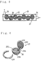
- Fig. 1 and Fig. 2 relate to the first embodiment of the present invention.
- Fig. 1 is a side sectional view.
- Fig. 2 is a cross sectional view.
- Fig. 3 and Fig. 4 relate to the second embodiment of the present invention.
- Fig. 3 is a side sectional view.
- Fig. 4 is a perspective view of the perforated small container which is opened.
- Fig. 5 and Fig. 6 relate to the third embodiment of the present invention.
- Fig. 5 is a side sectional view.
- Fig. 6 is a sectional view along the line A-A in Fig. 5
- Fig. 7 is a side sectional view of a traditional fuel treating device.
- a fuel treating device (11) shown in Fig. 1 and Fig. 2 consists of a fuel treating container (12) having a disk shape, a flow path (13) formed on the circumference of said fuel treating container (12), a fuel entrance (14) connecting diagonally to said flow path (13), a fuel exit (15) extended upward from said flow path (13) and a plural number of grain-shaped ceramics (16) arranged separately in said flow path (13).
- said grain-shaped ceramics (16) has a diameter in the range between 3 to 10 mm and preferably 5 to 7 mm.
- Said fuel F is agitated by said moving grain-shaped ceramics (16) and contacted effectively with said grain-shaped ceramics (16) and decomposed to an activated fuel having a low molecular weight by the energy from said grain-shaped ceramics (16).
- the resulting activated fuel having a low molecular weight has a high efficiency of combustion and little amount of C and CO are produced in combustion of said activated fuel.
- a fuel treating device (21) of this embodiment consists of a cylindrical fuel treating container (22) having a fuel entrance (24) at one end and a fuel exit (25) at the other end, a plural number of perforated small containers (27) arranged in said fuel treating container (22) and grain-shaped ceramics (26) packed in each perforated small container (27) wherein said perforated small container (27) has a spherical shape and consists of a pair of hemispherical cages (27B, 27C) connected by a hinge (27A) respectively and said hemispherical cages (27B, 27C) are closed by putting the circumference flanges (27D, 27E) of said hemispherical cages (27B, 27C) together and fixed by a lock band (27F).
- said grain-shaped ceramics (26) has a diameter in the range between 3 to 10 mm, preferably 5 to 7 mm and assuming the highest packing density of said grain-shaped ceramics (26) is 100 %.
- said grain-shaped ceramics (26) are packed in said perforated small container (27) at a packing density in the range between 60 to 70 % so that said grain-shaped ceramics (26) can move in said perforated small container (27).
- a fuel treating device (31) of this embodiment consists of a cylindrical fuel treating container (32) in which a flow path (33) is formed, a fuel entrance (34) connecting to one end of said fuel treating container (32) and a fuel exit (35) connecting to the other end of said fuel treating container (32) and a plural number of propeller-shaped ceramics (36) supported rotatably by frames (37) in said fuel treating container (32) wherein each propeller-shaped ceramics (36) is arranged toward the upper stream of the fuel flow.
- the number of said propeller-shaped ceramics (36) arranged in said fuel treating container (32) may not be limited in the present invention but it is preferable to arrange said propeller-shaped ceramics (36) as close as possible together so far as the flow resistance of said propeller-shaped ceramics (36) does not become remarkably large. Further, it is preferable to settle the diameter of said propeller-shaped ceramics (36) smaller than the inside diameter of said fuel treating container (32). Still further, in this embodiment, said propeller-shaped ceramics (36) has two wings but a propeller-shaped ceramics having three wings, a propeller-shaped ceramics having four wings, and a propeller-shaped ceramics having more than four wings may be used in the present invention.
- the fuel for automobile was treated by said fuel treating devices (11, 21, 31) and said traditional fuel treating device (1) shown in Fig. 7 as a comparison and practical driving test using an automobile on the market was carried out by using said treated fuel.
- fuel treating materials (16, 26, 36) A, A2, B, B2, C, C2, D, D2, E, E2 and F, F2 used in said fuel treating device (11, 21, 31) and a fuel treating material (7) G were respectively prepared as follows:
- ferric anchloride hydride 1 g was dissolved in 5 ml of 12 N aqueous solution of sodium hydroxide with agitation and said solution was kept for more than 5 hours at room temperature. Said solution was nuetralized by 12 N aqueous solution of hydrochloric acid at pH about 7 and said neutralized solution was filtrated through a filter paper (No. 5C) and then said filtrated solution was concentrated to deposite a crystal.
- the resulting crystal was collected and dried in a desiccator and then said dried crystal was dissolved in 10 ml of a mixture of iso-propanol and water (80 : 20 weight ratio). Said solution was filtrated by the filter paper (No. 5C) and after that concentrated to remove solvents to dry. Above described extraction-concentration-drying operation was repeated a few times to obtain a purified crystal of the activated ferric chloride. Said crystal was dissolved in the distilled water to prepare 2 ppm aqueous solution of said activated ferric chloride.
- the fuel treating materials A and A2 are identical to The fuel treating materials A and A2:
- Polyvinylalcohol and water were added in a mixture of silicone oxide and aluminium oxide (1 : 1 weight ratio) to mix and said mixture was molded to a spherical grain shape having a diameter 6 mm and then said grain was burned at 1000 °C for 3 hours to obtain spherical grain-shaped ceramics used for the fuel treating materials A and A2.
- the fuel treating materials C and C2 are the fuel treating materials C and C2:
- Polyvinylalcohol and water were added in a mixture of zirconium oxide and titanium oxide (1 : 1 weight ratio) to mix and said mixture was molded to a spherical grain shape having a diameter 6 mm and then said grain was burned at 1000 °C for 3 hours to obtain spherical grain-shaped ceramics used for the fuel treating materials C and C2.
- the fuel treating materials E and E2 are the fuel treating materials E and E2:
- the resulting fuel treating materials A2, C2 and E2 were respectively contacted with the air passed through said aqueous solution of said activated ferric chloride at a flow rate 5 l/min for 3 hours to obtain activated fuel treating materials.
- the resulting crystal was collected and vacuum-dried in a desiccator and said dried crystal was dissolved in 10 ml of a mixture of iso-propanol and water (80 : 20 weight ratio) and said solution was filtrated through a filter paper (No. 5C) followed by concentration of said filtrated solution to remove solvents to dry. Above described extraction-concentration-drying operation was repeated a few times to obtain a purified crystal of the activated ferric chloride.
- the fuel treating materials B and B2 are the fuel treating materials B and B2:
- Polyvinylalcohol and water were added in a mixture of silicone oxide and aluminium oxide (1 : 1 weight ratio) to mix and said mixture was molded to a spherical grain shape having a diameter 6 mm and then said grain was burned at 1000 °C for 3 hours to obtain spherical grain-shaped ceramics used for the fuel treating materials B and B2.
- the fuel treating materials D and D2 are The fuel treating materials D and D2:
- Polyvinylalcohol and water were added in a mixture of zirconium oxide and titanium oxide (1 : 1 weight ratio) to mix and said mixture was molded to a spherical grain shape having a diameter 6 mm and then said grain was burned at 1000 °C for 3 hours to obtain spherical grain-shaped ceramics used for the fuel treating materials D and D2.
- the fuel treating materials F and F2 are the fuel treating materials F and F2:
- Said resulting fuel treating materials B, D and F were dipped in said aqueous solution of said activated ferric chloride and kept for 2 hours and after that said fuel treating materials B, D and F were collected and vacuum-dried to obtain activated fuel treating materials.
- the resulting fuel treating materials B2, D2 and F2 were respectively contacted with the air passed through said aqueous solution of said activated ferric chloride at a flow rate 5 l/min for 3 hours to obtain activated fuel treating materials.
- Polyvinylalcohol and water were added in a mixture of silicone oxide and aluminium oxide (1 : 1 weight ratio) to mix and said mixture was molded to a spherical grain shape having a diameter 6 mm and then said grain was burned at 1000 °C for 3 hours to obtain spherical grain-shaped ceramics used for the fuel treating material G.
- Each fuel treating material A, A2, B and B2 was arranged separately in said fuel treating container (12) of the first embodiment as shown in Fig. 1 and Fig. 2 and each fuel treating material C, C2, D and D2 was packed in said perforated small container (27) of the second embodiment in a packing density 80 % as shown in Fig. 3 and Fig. 4 and then a plural number of said perforated small containers (27) were arranged in said fuel treating container (22) and each fuel treating material E, E2, F and F2 was arranged in said fuel treating container (32) of the third embodiment as shown in Fig. 5 and Fig. 6.
- a fuel treating device having a small pressure loss and a high contact efficiency between fuel and fuel treating material and therefore, a high efficiency of improvement of fuel is provided.
Landscapes
- Engineering & Computer Science (AREA)
- Chemical & Material Sciences (AREA)
- Chemical Kinetics & Catalysis (AREA)
- Combustion & Propulsion (AREA)
- Mechanical Engineering (AREA)
- General Engineering & Computer Science (AREA)
- Production Of Liquid Hydrocarbon Mixture For Refining Petroleum (AREA)
- Liquid Carbonaceous Fuels (AREA)
- Compounds Of Iron (AREA)
Applications Claiming Priority (4)
| Application Number | Priority Date | Filing Date | Title |
|---|---|---|---|
| JP9366594A JPH07224730A (ja) | 1993-12-15 | 1994-04-06 | 燃料処理装置 |
| JP9366594 | 1994-04-06 | ||
| JP93665/94 | 1994-04-06 | ||
| PCT/JP1995/000684 WO1995027849A1 (en) | 1994-04-06 | 1995-04-06 | Fuel treatment device |
Publications (3)
| Publication Number | Publication Date |
|---|---|
| EP0708237A1 true EP0708237A1 (de) | 1996-04-24 |
| EP0708237A4 EP0708237A4 (de) | 1997-12-29 |
| EP0708237B1 EP0708237B1 (de) | 2003-01-22 |
Family
ID=14088703
Family Applications (1)
| Application Number | Title | Priority Date | Filing Date |
|---|---|---|---|
| EP95914537A Expired - Lifetime EP0708237B1 (de) | 1994-04-06 | 1995-04-06 | Brennstoffbehandlungsvorrichtung |
Country Status (7)
| Country | Link |
|---|---|
| US (1) | US5695531A (de) |
| EP (1) | EP0708237B1 (de) |
| KR (1) | KR960702887A (de) |
| AU (1) | AU2148095A (de) |
| DE (1) | DE69529449T2 (de) |
| TW (1) | TW314573B (de) |
| WO (1) | WO1995027849A1 (de) |
Cited By (4)
| Publication number | Priority date | Publication date | Assignee | Title |
|---|---|---|---|---|
| EP0791745A1 (de) * | 1996-02-23 | 1997-08-27 | Nobuyoshi Nishikawa | Verfahren zur Reformierung von Brennstoff, Brennstoffreformiervorrichtung und Wärmekraftmaschine |
| EP1178206A1 (de) * | 2000-02-16 | 2002-02-06 | Motonari Koyama | Verbrennungsverbessernde Einrichtung und Verfahren zu deren Verwendung |
| WO2004020070A1 (en) * | 2002-08-30 | 2004-03-11 | Honeywell International Inc. | Staged oil filter incorporating timed release oil conditioner |
| US7316778B2 (en) | 2000-05-08 | 2008-01-08 | Honeywell International, Inc. | Staged oil filter incorporating pelletized basic conditioner |
Families Citing this family (19)
| Publication number | Priority date | Publication date | Assignee | Title |
|---|---|---|---|---|
| US6860241B2 (en) | 1999-06-16 | 2005-03-01 | Dober Chemical Corp. | Fuel filter including slow release additive |
| US6203586B1 (en) * | 2000-01-12 | 2001-03-20 | John W. Davis | Fire enhancement system |
| US6835218B1 (en) | 2001-08-24 | 2004-12-28 | Dober Chemical Corp. | Fuel additive compositions |
| DE10297145T5 (de) | 2001-08-24 | 2004-07-22 | Dober Chemical Corporation, Midlothian | Kontrollierte Freisetzung von Additiven in Fluidsysteme |
| US6827750B2 (en) | 2001-08-24 | 2004-12-07 | Dober Chemical Corp | Controlled release additives in fuel systems |
| US7938277B2 (en) | 2001-08-24 | 2011-05-10 | Dober Chemical Corporation | Controlled release of microbiocides |
| US7001531B2 (en) | 2001-08-24 | 2006-02-21 | Dober Chemical Corp. | Sustained release coolant additive composition |
| US6843916B2 (en) | 2002-07-16 | 2005-01-18 | The Lubrizol Corporation | Slow release lubricant additives gel |
| US7384896B2 (en) * | 2002-07-16 | 2008-06-10 | The Lubrizol Corporation | Controlled release of additive gel(s) for functional fluids |
| WO2004013484A2 (en) * | 2002-08-01 | 2004-02-12 | Briggs & Stratton Corporation | Drip feed apparatus for a fuel container |
| US6981532B2 (en) * | 2002-08-01 | 2006-01-03 | Briggs & Stratton Corporation | Drip feed apparatus for a fuel container |
| US7534747B2 (en) * | 2003-06-25 | 2009-05-19 | The Lubrizol Corporation | Gels that reduce soot and/or emissions from engines |
| US7563368B2 (en) | 2006-12-12 | 2009-07-21 | Cummins Filtration Ip Inc. | Filtration device with releasable additive |
| US8022021B2 (en) * | 2007-02-05 | 2011-09-20 | The Lubrizol Corporation | Low ash controlled release gels |
| US20090294379A1 (en) * | 2008-05-27 | 2009-12-03 | Dober Chemical Corporation | Controlled release of additive compositions |
| US8591747B2 (en) | 2008-05-27 | 2013-11-26 | Dober Chemical Corp. | Devices and methods for controlled release of additive compositions |
| US7883638B2 (en) | 2008-05-27 | 2011-02-08 | Dober Chemical Corporation | Controlled release cooling additive compositions |
| US8702995B2 (en) | 2008-05-27 | 2014-04-22 | Dober Chemical Corp. | Controlled release of microbiocides |
| MX2019013783A (es) * | 2019-11-19 | 2021-05-20 | Carey Gipson | Dispositivo para el tratamiento de combustible. |
Family Cites Families (18)
| Publication number | Priority date | Publication date | Assignee | Title |
|---|---|---|---|---|
| GB524881A (en) * | 1938-02-26 | 1940-08-16 | Hellenique Ind Des Gazofacteur | Improved process and apparatus for gasifying heavy hydrocarbon for use in internal combustion engines |
| US2955028A (en) * | 1955-10-17 | 1960-10-04 | Ethyl Corp | Fuel systems for compression ignition engines |
| US3789096A (en) * | 1967-06-01 | 1974-01-29 | Kaman Sciences Corp | Method of impregnating porous refractory bodies with inorganic chromium compound |
| GB1402207A (en) * | 1972-03-03 | 1975-08-06 | Siemens Ag | Catalyst and its use in hydrocarbon cracking processes |
| US4106478A (en) * | 1975-06-09 | 1978-08-15 | Sunao Higashijima | Packaged heat generator |
| US4282084A (en) * | 1978-09-27 | 1981-08-04 | Mobil Oil Corporation | Catalytic cracking process |
| JPS5569684A (en) * | 1978-11-20 | 1980-05-26 | Akinobu Fujiwara | Pyrogen |
| US4407967A (en) * | 1979-08-16 | 1983-10-04 | Frenchtown American Corp. | Method for producing spheroidal ceramics |
| US4404152A (en) * | 1980-11-24 | 1983-09-13 | Phillips Petroleum Company | Iron-containing refractory balls for retorting oil shale |
| JPS59160847U (ja) * | 1983-04-14 | 1984-10-27 | 弘保 亘 | 燃料油の磁化装置 |
| US4478607A (en) * | 1983-08-03 | 1984-10-23 | Turra International, Inc. | Device for atomizing and dispersing fuel in a fuel/air mixture |
| JPH01116275A (ja) * | 1987-10-28 | 1989-05-09 | Kenji Yakura | 燃料処理方法およびその燃料処理装置 |
| JPH03213653A (ja) * | 1990-01-19 | 1991-09-19 | Nissho Rajiekoo Kk | 燃焼機関の燃費向上方法 |
| JPH0499289A (ja) * | 1990-08-08 | 1992-03-31 | Sumitomo Metal Ind Ltd | エッチング方法 |
| US5059217A (en) * | 1990-10-10 | 1991-10-22 | Arroyo Melvin L | Fluid treating device |
| DE4129408C1 (de) * | 1991-09-04 | 1992-10-22 | Chemische Betriebe Pluto Gmbh, 4690 Herne, De | |
| JPH062622A (ja) * | 1992-06-18 | 1994-01-11 | Mamoru Miyano | 炭化水素系燃料の高燃焼化処理装置 |
| US5305725A (en) * | 1992-09-11 | 1994-04-26 | Marlow John R | Method and apparatus for treating fuel |
-
1995
- 1995-04-06 KR KR1019950705498A patent/KR960702887A/ko not_active Withdrawn
- 1995-04-06 DE DE69529449T patent/DE69529449T2/de not_active Expired - Fee Related
- 1995-04-06 US US08/556,975 patent/US5695531A/en not_active Expired - Fee Related
- 1995-04-06 WO PCT/JP1995/000684 patent/WO1995027849A1/ja not_active Ceased
- 1995-04-06 EP EP95914537A patent/EP0708237B1/de not_active Expired - Lifetime
- 1995-04-06 AU AU21480/95A patent/AU2148095A/en not_active Abandoned
- 1995-05-19 TW TW084104967A patent/TW314573B/zh active
Cited By (4)
| Publication number | Priority date | Publication date | Assignee | Title |
|---|---|---|---|---|
| EP0791745A1 (de) * | 1996-02-23 | 1997-08-27 | Nobuyoshi Nishikawa | Verfahren zur Reformierung von Brennstoff, Brennstoffreformiervorrichtung und Wärmekraftmaschine |
| EP1178206A1 (de) * | 2000-02-16 | 2002-02-06 | Motonari Koyama | Verbrennungsverbessernde Einrichtung und Verfahren zu deren Verwendung |
| US7316778B2 (en) | 2000-05-08 | 2008-01-08 | Honeywell International, Inc. | Staged oil filter incorporating pelletized basic conditioner |
| WO2004020070A1 (en) * | 2002-08-30 | 2004-03-11 | Honeywell International Inc. | Staged oil filter incorporating timed release oil conditioner |
Also Published As
| Publication number | Publication date |
|---|---|
| EP0708237A4 (de) | 1997-12-29 |
| KR960702887A (ko) | 1996-05-23 |
| EP0708237B1 (de) | 2003-01-22 |
| DE69529449T2 (de) | 2003-10-23 |
| TW314573B (de) | 1997-09-01 |
| US5695531A (en) | 1997-12-09 |
| WO1995027849A1 (en) | 1995-10-19 |
| AU2148095A (en) | 1995-10-30 |
| DE69529449D1 (de) | 2003-02-27 |
Similar Documents
| Publication | Publication Date | Title |
|---|---|---|
| EP0708237A1 (de) | Brennstoffbehandlungsvorrichtung | |
| Ding et al. | Efficient degradation of chloroquine phosphate by peroxymonosulfate activated using reusable lanthanide cobalt-copper perovskite-cerium dioxide composite catalyst: Performance, mechanism and degradation pathway | |
| CN109364892A (zh) | 一种用于烟气净化的高效吸附材料 | |
| CN109046368B (zh) | 一种煤化工废水深度氧化催化剂及其制备方法 | |
| KR20220159247A (ko) | 유기-일라이트 복합 분체와 이의 제조 방법, 및 이를 포함하는 화장료 조성물 | |
| DE2155240C3 (de) | Vorrichtung zur kontinuierlichen Behandlung, z.B. durch Trocknung oder Kühlung von staub-, pulver- und granulatförmigem Material | |
| CN109759139B (zh) | 一种环保型污水处理用光催化材料及其制备方法 | |
| CN114874842A (zh) | 一种养肝护肝的灵芝孢子油提取物的生产工艺 | |
| CN110404504B (zh) | 用于处理印染污水的Cu掺杂核桃壳活性炭及其制法和应用 | |
| US20250050281A1 (en) | Preparation Method of Nanofiltration Membrane with Tree-Like Structure and Use | |
| CN105565457A (zh) | 一种重金属污水的处理方法 | |
| CN118222055B (zh) | 一种保鲜功能水性母粒及其制备方法 | |
| Manolova et al. | Polyether-modified fullerenes | |
| Aljeboree et al. | Removal of amoxicillin drug onto nano composites surface using ultrasound assistance. | |
| CN117324040B (zh) | 一种聚酰亚胺复合苯乙炔铜光催化剂及其制备方法、应用 | |
| CN117586520A (zh) | 一种壳寡糖-铜基金属有机框架材料的制备与应用 | |
| JPH07224730A (ja) | 燃料処理装置 | |
| CN118575915B (zh) | 一种呕吐毒素吸附剂及其制备方法和应用 | |
| CN107244885A (zh) | 一种光催化陶瓷粉体材料及其制备方法 | |
| CN106866831A (zh) | 茯苓酸性多糖提取物的制备方法及用途 | |
| CN111921494A (zh) | 一种文冠果活性炭吸附剂及其制备方法和应用 | |
| CN1369214A (zh) | 广泛脱毒剂 | |
| CN113477230A (zh) | 一种含有改性硅藻土的助滤剂及其制备方法 | |
| CN110386711A (zh) | 一种垃圾渗滤液的管式自由基氧化处理的方法 | |
| El-Sheikh et al. | Role of resin-copper (II) complexes containing ethanolamines in hydrogen peroxide decomposition |
Legal Events
| Date | Code | Title | Description |
|---|---|---|---|
| PUAI | Public reference made under article 153(3) epc to a published international application that has entered the european phase |
Free format text: ORIGINAL CODE: 0009012 |
|
| 17P | Request for examination filed |
Effective date: 19951221 |
|
| AK | Designated contracting states |
Kind code of ref document: A1 Designated state(s): DE FR GB |
|
| A4 | Supplementary search report drawn up and despatched | ||
| AK | Designated contracting states |
Kind code of ref document: A4 Designated state(s): DE FR GB |
|
| 17Q | First examination report despatched |
Effective date: 20010215 |
|
| GRAG | Despatch of communication of intention to grant |
Free format text: ORIGINAL CODE: EPIDOS AGRA |
|
| GRAG | Despatch of communication of intention to grant |
Free format text: ORIGINAL CODE: EPIDOS AGRA |
|
| GRAH | Despatch of communication of intention to grant a patent |
Free format text: ORIGINAL CODE: EPIDOS IGRA |
|
| GRAH | Despatch of communication of intention to grant a patent |
Free format text: ORIGINAL CODE: EPIDOS IGRA |
|
| GRAA | (expected) grant |
Free format text: ORIGINAL CODE: 0009210 |
|
| AK | Designated contracting states |
Kind code of ref document: B1 Designated state(s): DE FR GB |
|
| REG | Reference to a national code |
Ref country code: GB Ref legal event code: FG4D |
|
| REF | Corresponds to: |
Ref document number: 69529449 Country of ref document: DE Date of ref document: 20030227 Kind code of ref document: P |
|
| PGFP | Annual fee paid to national office [announced via postgrant information from national office to epo] |
Ref country code: GB Payment date: 20030402 Year of fee payment: 9 |
|
| PGFP | Annual fee paid to national office [announced via postgrant information from national office to epo] |
Ref country code: FR Payment date: 20030408 Year of fee payment: 9 |
|
| PGFP | Annual fee paid to national office [announced via postgrant information from national office to epo] |
Ref country code: DE Payment date: 20030417 Year of fee payment: 9 |
|
| ET | Fr: translation filed | ||
| PLBE | No opposition filed within time limit |
Free format text: ORIGINAL CODE: 0009261 |
|
| STAA | Information on the status of an ep patent application or granted ep patent |
Free format text: STATUS: NO OPPOSITION FILED WITHIN TIME LIMIT |
|
| 26N | No opposition filed |
Effective date: 20031023 |
|
| PG25 | Lapsed in a contracting state [announced via postgrant information from national office to epo] |
Ref country code: GB Free format text: LAPSE BECAUSE OF NON-PAYMENT OF DUE FEES Effective date: 20040406 |
|
| PG25 | Lapsed in a contracting state [announced via postgrant information from national office to epo] |
Ref country code: FR Free format text: LAPSE BECAUSE OF NON-PAYMENT OF DUE FEES Effective date: 20041029 |
|
| PG25 | Lapsed in a contracting state [announced via postgrant information from national office to epo] |
Ref country code: DE Free format text: LAPSE BECAUSE OF NON-PAYMENT OF DUE FEES Effective date: 20041103 |
|
| GBPC | Gb: european patent ceased through non-payment of renewal fee | ||
| REG | Reference to a national code |
Ref country code: FR Ref legal event code: ST |