EP0708527B1 - Verfahren und Vorrichtung zum Regeln der Ausgangsleistung eines Leistungsverstärkers - Google Patents
Verfahren und Vorrichtung zum Regeln der Ausgangsleistung eines Leistungsverstärkers Download PDFInfo
- Publication number
- EP0708527B1 EP0708527B1 EP95116561A EP95116561A EP0708527B1 EP 0708527 B1 EP0708527 B1 EP 0708527B1 EP 95116561 A EP95116561 A EP 95116561A EP 95116561 A EP95116561 A EP 95116561A EP 0708527 B1 EP0708527 B1 EP 0708527B1
- Authority
- EP
- European Patent Office
- Prior art keywords
- output
- control signal
- power amplifier
- power
- output control
- Prior art date
- Legal status (The legal status is an assumption and is not a legal conclusion. Google has not performed a legal analysis and makes no representation as to the accuracy of the status listed.)
- Expired - Lifetime
Links
- 238000000034 method Methods 0.000 title claims description 5
- 230000007423 decrease Effects 0.000 claims description 4
- 238000001514 detection method Methods 0.000 claims 18
- 230000005540 biological transmission Effects 0.000 description 4
- 238000012544 monitoring process Methods 0.000 description 4
- 239000000470 constituent Substances 0.000 description 2
- 238000010586 diagram Methods 0.000 description 2
- 238000012986 modification Methods 0.000 description 2
- 230000004048 modification Effects 0.000 description 2
- 239000003990 capacitor Substances 0.000 description 1
- 238000005516 engineering process Methods 0.000 description 1
- 230000010355 oscillation Effects 0.000 description 1
- 230000001737 promoting effect Effects 0.000 description 1
Images


Classifications
-
- H—ELECTRICITY
- H03—ELECTRONIC CIRCUITRY
- H03G—CONTROL OF AMPLIFICATION
- H03G3/00—Gain control in amplifiers or frequency changers
- H03G3/20—Automatic control
-
- H—ELECTRICITY
- H03—ELECTRONIC CIRCUITRY
- H03G—CONTROL OF AMPLIFICATION
- H03G3/00—Gain control in amplifiers or frequency changers
- H03G3/20—Automatic control
- H03G3/30—Automatic control in amplifiers having semiconductor devices
- H03G3/3036—Automatic control in amplifiers having semiconductor devices in high-frequency amplifiers or in frequency-changers
- H03G3/3042—Automatic control in amplifiers having semiconductor devices in high-frequency amplifiers or in frequency-changers in modulators, frequency-changers, transmitters or power amplifiers
-
- H—ELECTRICITY
- H03—ELECTRONIC CIRCUITRY
- H03G—CONTROL OF AMPLIFICATION
- H03G3/00—Gain control in amplifiers or frequency changers
- H03G3/001—Digital control of analog signals
Definitions
- the present invention relates to a method of controlling the output power of a power amplifier, and a device therefor.
- a control device using a feedback scheme For the automatic control over the output of a power amplifier, a control device using a feedback scheme has been proposed in various forms in the past. This type of control device detects power output from a power amplifier, compares it with a reference value, and controls the gain of the amplifier such that the difference between the detected power output and the reference value is reduced to zero or a particular value. As a result, the output of the amplifier is automatically controlled to a predetermined target value.
- Such a control device is disclosed in Japanese Utility Model Laid-Open Publication No. 5-9018 by way of example and also in WO 86/07216.
- the conventional feedback type control device is implemented as a so-called closed loop.
- the stability of the loop gain is deteriorated, as obvious from the general theory. Consequently, the power amplifier output becomes unstable even when the predetermined output must be maintained.
- the constituent parts of the closed loop each has a frequency characteristic and is apt to_oscillate when the loop gain is greater than 1 and causes the phase to be inverted.
- the increase in loop gain aggravates the probability of oscillation. Therefore, the loop gain cannot be increased beyond a certain limit, resulting in slow control response.
- the output control device has a transmission power circuit 1, a directional coupler 2, an APC detector 3, an error amplifier 4, a CPU 5, a controller 6, a temperature sensor 7, an analog-to-digital (A/D) converter 8, and a digital-to-analog (D/A) converter 9.
- the directional coupler 2 separates a part of the output of the transmission power circuit 1 and feeds it to the APC detector 3.
- the resulting output of the detector 3 is applied to the error amplifier 4.
- the error amplifier 4 compares the output of the detector 3 and a reference voltage fed from the CPU 5 and delivers a difference between them, i.e., an error to the controller 6.
- the controller 6 controls the gain of the transmission power circuit 1 on the basis of the error.
- the CPU 5 corrects the reference voltage, and therefore the output of the transmission power circuit 1 on the basis of temperature sensed by the temperature sensor 7.
- the above feedback control based on the output of the power amplifier constitutes a so-called closed loop.
- an output control device not relying on a closed loop may be contemplated and is practicable if a control signal is fed from the outside of the device.
- a control signal is fed from the outside of the device.
- this kind of scheme i.e., by directly controlling the gain of the power amplifier by an outside control signal, it is possible to change the gain more rapidly.
- the control signal must be highly accurate and stable. With the state-of-the-art technologies, it is difficult to produce such an accurate and stable control signal, and therefore to accurately and stably control the output of the power amplifier.
- the control device has a power amplifier 11, a coupler 12, a detector 13, an A/D converter 14, a D/A converter 15, a CPU 16, and a storage 17 which may preferably be implemented by an EEPROM.
- the coupler 12 has a resistor 121 and a distributed constant circuit 122.
- the detector 13 has a diode 131 and a capacitor 132.
- the power amplifier 11 receives a signal to be transmitted via an input terminal IN, amplifies the power of the signal, and then produces the amplified signal on an output terminal OUT which is connected to an antenna.
- the power amplifier 11 additionally has a control terminal CONT and is implemented as a variable gain control amplifier. A control signal is applied to the control terminal CONT in order to variably control the gain and, therefore, the output of the amplifier 11.
- the coupler 12 separates a part of the output of the amplifier 11 and applies it to the detector 13.
- the detector 13 detects the input signal and then outputs a DC voltage corresponding to the output level.
- the A/D converter 14 converts the DC voltage output from the detector 13 to a digital value.
- the CPU 16 is connected to the control terminal CONT of the power amplifier 11 via the D/A converter 15.
- the D/A converter 15 transforms a control signal 100 output from the CPU 16 (referred to as an output control signal hereinafter) to an analog value and then delivers it to the amplifier 11. As a result, the gain of the amplifier 11 is controlled in accordance with the analog value.
- the digital value or signal from the A/D converter 14 is applied to the CPU 16.
- the CPU 16 is capable of writing or reading data in or out of the storage, preferably EEPROM, 17, as needed.
- An outside control terminal OT is connected to the CPU 16.
- the CPU 16 produces the output control signal 100 matching a control signal 101 fed thereto via the outside control terminal OT (referred to as an outside control signal hereinafter).
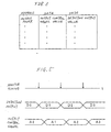
- FIG. 3 shows an address map representative of data stored in the storage 17 at the time of initial setting.
- output power values to be actually output from the power amplifier 11 are stored in the storage 17 as addresses.
- the outputs of the A/D converter 14 to be input to the CPU 16 and the output control signals 100 to be output from the CPU 16 to the D/A converter 15 and each corresponding to the respective output power, or address, are also stored in the storage 17 as data. This can be done by sequentially varying the output control signal 100 in accordance with a preselected program, measuring the resulting outputs of the power amplifier 11, i.e., output power values as well as the resulting outputs of the A/D converter 14, and then writing them in the storage 17 at a time.
- the CPU 16 determines whether or not it has received the outside control signal 101 via the outside control terminal OT (step S1001).
- the control signal 101 is representative of the target output value of the power amplifier 11. If the answer of the step S1001 is negative (NO), then the program returns. If the answer of the step S1001 is positive (YES), then the CPU 16 reads one of the output control signals 100 and one of the detector outputs out of the address of the storage 17 where the designated target output power value is stored (step S1002). The CPU 16 feeds only the output control signal 100 read out of the storage 17 to the D/A converter 5 (step S1003).
- the output control signal 100 is transformed to an analog signal by the D/A converter 15 and then input to the power amplifier 11 via the control terminal CONT.
- the power amplifier 11 has its gain controlled by the output control signal 100 and produces an amplified signal on the output terminal OUT.
- the output of the power amplifier 11 is detected by the coupler 12 and detector 13 as a DC voltage at a predetermined monitoring time.
- the detected output is converted to a digital signal by the A/D converter 14 and then input to the CPU 16 (step S1004).
- the CPU 16 compares the input detector output and the detector output read out of the storage 17 previously (step S1005). If the two detector outputs compare equal (step 1006, YES), the CPU 16 does not vary the current value of the output control signal 100. Hence, the target output continuously appears on the output terminal OUT.
- step S1006 determines that the target power is not output from the power amplifier 11, and changes the value of the output control signal 100 on the basis of the following specific steps.
- the CPU 16 reads the detector outputs out of several addresses preceding and succeeding the previous read out address (step S1008). Then, the CPU 16 selects one of the several detector outputs closest to the detector output actually input to the CPU 16 (step S1009). Subsequently, the CPU 16 reads out the output control signal 100 stored in the same address as the detector output selected (step S1010) and then delivers it to the D/A converter 15 (step S1010).
- the control signal 100 varies the gain of the power amplifier 11. Therefore, the resulting detector output becomes closer to the detector output read out of the storage 17 first.
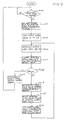
- FIG. 5 shows how the CPU 16 receives, or monitors, the detector output from the A/D converter 14 and delivers the output control signal 100 to the D/A converter 15 specifically.
- the CPU 16 receives a detector output from the A/D converter 14 at a time for monitoring, as indicated by an arrow in the figure.
- the CPU 16 produces an output control signal 100 whose value is A0.
- the CPU 16 receives a detector output D1 and then produces an output control signal 100 whose value is A1. This is repeated until the target power appears on the output terminal OUT.
- the CPU 16 divides the difference by a preselected value, increments or decrements the address by the quotient, reads out an output control signal 100 stored in the resulting address, and then delivers it to the D/A converter 15. If the quotient has a residual, the CPU 16 further increments or decrements the address by 1 (one), reads an output control signal 100, and then delivers it to the D/A converter 15. This successfully prevents the output of the power amplifier 11 from sharply varying.
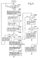
- FIG. 6 is a flow-chart illustrating the above-described function.
- steps S2001-S2007 are identical with the steps S1001-S1007 of FIG. 5, respectively, and will not be described in order to avoid redundancy. If a detector output V 1 from the A/D converter 14 is not equal to a detector output V 2 read out previously (step S2006, NO), the CPU 16 compares a difference D between the detector outputs V 1 and V 2 with a preselected reference value DT (step S2008).
- step S2008, NO the CPU 16 reads detector outputs stored in several addresses preceding and following the address read out previously (step S2009), selects the address storing a detector output closest to the actually input detector output (step S2010), and then delivers an output control signal 100 stored in the address selected to the D/A converter 5. This varies the gain of the power amplifier 11 and thereby allows the resulting detector output to be closer to the detector output read out previously.
- step S2012 the CPU 16 divides the difference D by a preselected value VT (step S2012).
- the CPU 16 determines whether or not the quotient of the division, D/VT has a residue (step S2013). If the answer of the step S2013 is NO, the CPU 16 increments or decrements the address by the quotient, reads an output control signal 100 out of the incremented or decremented address, and then delivers it to the D/A converter 15 (step S2014). If the answer of the step S2013 is YES, the CPU 16 further increments or decrements the address by 1, reads an output control signal out of the resulting address, and then feeds it to the D/A converter 15 (step S2015). As a result, the output of the power amplifier 11 is prevented from sharply varying.
- the illustrative embodiment controls the gain of the power amplifier 11 on the basis of data stored in the storage 17 beforehand.
- the output of the power amplifier 11 is controlled by the closed loop constituted by the coupler 12, detector 13, A/D converter 14 and D/A converter 15, the output control signal 100 for the control is fed from the storage 17 which is independent of the loop. Therefore, the control depends solely on the accuracy of data stored in the storage 17; the response and accuracy of the output control is not related to the the gain of the loop.
- stable control over the output power is enhanced.
- the response will be further enhanced if the interval between the consecutive times for the CPU 16 to monitor the detector output is reduced.
- the embodiment controls the output power in response to an outside control signal, it implements fast control response because it reads data out of the storage 17 on the basis of the outside control signal. Further, if the outside control signal is implemented by a digital signal, the embodiment can execute accurate and stable control without regard to the accuracy or the stability of the control signal.
- signal processing means reads, in response to an outside control signal and a detector output representative of the output power of a power amplifier, a corresponding output control signal out of a storage and controls the output power on the basis of the control signal.
- the output control signal is fed from the storage which is independent of a loop including a detector for detecting the power output and the signal processing means. It follows that the response and accuracy of the output control are not related to the gain of the loop. This implements highly accurate control relying solely on the accuracy of data stored in the storage, while promoting stable control. In addition, the response of the output control can be enhanced in matching relation to the operation speed of the signal processing means.
- the signal processing means compares the detector output read out of the storage and the detector output appearing at predetermined intervals, and varies the output control signal such that a difference between them decreases. This allows the output power of the power amplifier to be automatically controlled to an adequate value matching the outside control signal.
- the embodiment divides it by a preselected value, and then varies the output control signal a plurality of times stepwise on the basis of the quotient. Hence, the output power of the power amplifier is prevented from sharply varying.
- the output power values of the power amplifier are stored in the storage as addresses beforehand, while detector outputs and output control signals each matching the respective address are stored in the storage.
- the embodiment therefore, produces an output control signal matching desired output voltage immediately and thereby controls the gain of the amplifier rapidly, accurately, and stably.
Landscapes
- Control Of Amplification And Gain Control (AREA)
- Amplifiers (AREA)
- Transmitters (AREA)
- Tone Control, Compression And Expansion, Limiting Amplitude (AREA)
Claims (5)
- Vorrichtung zum Steuern der Ausgangsleistung eines Leistungsverstärkers mit einem Leistungsverstärker mit einer in Antwort auf ein Ausgangsleistungssteuersignal variablen Verstärkung und einer Erfassungseinrichtung zum Erfassen der Ausgangsleistung des Leistungsverstärkers;
dadurch gekennzeichnet, daß die Vorrichtung ferner aufweist:eine Signalverarbeitungseinrichtung zum Zuführen des Ausgangsleistungssteuersignals (100) in Antwort auf ein Erfassungsausgangssignal der Erfassungseinrichtung und ein extern zugeführtes externes Steuersignal (101) zum Steuern der Ausgangsleistung des Leistungsverstärkers (11) zum Leistungsverstärkers (11); undeinen Speicher (17) zum Speichern verschiedener Werte des Erfassungsausgangssignals und verschiedener Werte des Ausgangsleistungssteuersignals (100) gemäß verschiedenen Werten der vom Leistungsverstärker (11) auszugebenden Leistung;wobei die Signalverarbeitungseinrichtung in Antwort auf das Erfassungsausgangssignal und das ihr zugeführte externe Steuersignal einen entsprechenden der verschiedenen Werte des Ausgangsleistungssteuersignals aus dem Speicher (17) ausliest und das Ausgangsleistungssteuersignal (100) mit diesem Wert dem Leistungsverstärker (11) zuführt, um die Verstärkung des Leistungsverstärkers (11) zu steuern; undwobei die Signalverarbeitungseinrichtung ein aus dem Speicher ausgelesenes Erfassungsausgangssignal in einem bestimmten Zeitintervall mit dem der Signalverarbeitungseinrichtung zugeführten Erfassungsausgangssignal vergleicht und das Ausgangsleistungssteuersignal (100) so variiert, daß eine Differenz zwischen den Erfassungsausgangssignalen abnimmt;wobei, wenn die Differenz größer ist als ein vorgegebener Wert, die Signalverarbeitungseinrichtung die Differenz durch eine vorgegebene Zahl teilt und dann das Ausgangsleistungssteuersignal basierend auf der geteilten Differenz mehrmals schrittweise variiert. - Vorrichtung nach Anspruch 1, wobei der Speicher verschiedene Werte der Ausgangsleistung als Adressen speichert und die verschiedenen Werte des Erfassungausgangssignals und die verschiedenen Werte des Ausgangsleistungssteuersignals in den entsprechenden Adressen speichert.
- Vorrichtung zum Steuern der Ausgangsleistung eines Leistungsverstärkers mit:einem D/A-Wandler (15) zum Umwandeln eines digitalen Ausgangsleistungssteuersignals in ein analoges Signal;einem Leistungsverstärker (11) mit einer in Antwort auf das Ausgangsleistungssteuersignal (100) vom D/A-Wandler (15) variablen Verstärkung;einem Koppler (12) zum Erfassen eines Teils der Ausgangsleistung des Leistungsverstärkers (11);einem Detektor (13) zum Erfassen eines Ausgangssignals des Kopplers (12) und zum Erzeugen einer entsprechenden Gleichspannung;einem A/D-Wandler (14) zum Umwandeln eines Ausgangssignals des Detektors (13) in einen digitalen Wert;einer Zentraleinheit (16) zum Zuführen des digitalen Ausgangsleistungssteuersignals in Antwort auf ein Ausgangssignal des A/D-Wandlers (14) und ein extern zugeführtes Steuersignal (101) zum Steuern der Ausgangsleistung des Leistungsverstärkers (11) zum D/A-Wandler (15); undeinem ROM-Speicher (17) zum Speichern verschiedener Werte eines vom A/D-Wandler (14) auszugebenden Erfassungsausgangssignals und verschiedener Werte des von der Zentraleinheit (16) gemäß jeweiligen Werten der vom Leistungsverstärker (11) auszugebenden Leistung auszugebenden digitalen Ausgangsleistungssteuersignals;wobei die Zentraleinheit (16) in Antwort auf das externe Steuersignal (101) und das Ausgangssignal des A/D-Wandlers (14) ein entsprechendes der digitalen Ausgangsleistungssteuersignale aus dem ROM-Speicher (17) ausliest und das eine digitale Ausgangsleistungssteuersignal dem D/A-Wandler (15) zuführt; undwobei die Zentraleinheit (16) ein aus dem Speicher (17) ausgelesenes Erfassungsausgangssignal in einem bestimmten Zeitintervall mit dem Erfasungsausgangssignal vergleicht, das der Signalverarbeitungseinrichtung zugeführt wird, und das Ausgangsleistungssteuersignal so variiert, daß die Differenz zwischen den Erfassungsausgangssignalen abnimmt; undwobei, wenn die Differenz größer ist als ein vorgegebener Wert, die Zentraleinheit (16) die Differenz durch eine vorgegebene Zahl teilt und das Ausgangsleistungssteuersignal dann basierend auf der geteilten Differenz mehrmals schrittweise variiert.
- Vorrichtung nach Anspruch 3, wobei der ROM-Speicher die Ausgangsleistungswerte als Adressen speichert und die Erfassungsausgangssignale und die Ausgangsleistungsteuersignale den jeweiligen Adressen zugeordnet sind.
- Verfahren zum Steuern der Ausgangsleistung eines Leistungsverstärkers mit den Schritten:Erfassen der Ausgangsleistung eines Leistungsverstärkers (11);Bereitstellen eines die Ausgangsleistung darstellenden Erfassungsausgangssignals und eines externen Steuersignals zum Steuern der Ausgangsleistung und Zuführen eines Ausgangsleistungssteuersignals zum Leistungsverstärker;Auslesen eines im voraus gespeicherten Ausgangsleistungssteuersignals in Antwort auf das Erfassungsausgangssignal und das bereitgestellte externe Steuersignal und Angleichen des Erfassungsausgangssignals und des externen Steuersignals; undZuführen des Ausgangsleistungssteuersignals zum Leistungsverstärker (11), um die Verstärkung des Leistungsverstärkers (11) zu steuern;wobei das Erfassungsausgangssignal in einem vorgegebenen Zeitintervall zugeführt und mit einem ebenfalls im voraus gespeicherten Erfassungsausgangssignal verglichen wird, und wobei das Ausgangsleistungssteuersignal so variiert wird, daß eine Differenz zwischen den Erfassungsausgangssignalen abnimmt; undwobei, wenn die Differenz größer ist als ein vorgegebener Wert, die Differenz durch eine vorgegebene Zahl geteilt und das Ausgangsleistungssteuersignal dann basierend auf der geteilten Differenz mehrmals schrittweise variiert wird.
Applications Claiming Priority (3)
| Application Number | Priority Date | Filing Date | Title |
|---|---|---|---|
| JP28292494 | 1994-10-21 | ||
| JP28292494A JPH08125469A (ja) | 1994-10-21 | 1994-10-21 | 電力増幅器の出力制御装置 |
| JP282924/94 | 1994-10-21 |
Publications (2)
| Publication Number | Publication Date |
|---|---|
| EP0708527A1 EP0708527A1 (de) | 1996-04-24 |
| EP0708527B1 true EP0708527B1 (de) | 2001-09-26 |
Family
ID=17658883
Family Applications (1)
| Application Number | Title | Priority Date | Filing Date |
|---|---|---|---|
| EP95116561A Expired - Lifetime EP0708527B1 (de) | 1994-10-21 | 1995-10-20 | Verfahren und Vorrichtung zum Regeln der Ausgangsleistung eines Leistungsverstärkers |
Country Status (7)
| Country | Link |
|---|---|
| US (1) | US5656972A (de) |
| EP (1) | EP0708527B1 (de) |
| JP (1) | JPH08125469A (de) |
| KR (1) | KR0168244B1 (de) |
| AU (1) | AU692920B2 (de) |
| CA (1) | CA2160960C (de) |
| DE (1) | DE69522889T2 (de) |
Families Citing this family (52)
| Publication number | Priority date | Publication date | Assignee | Title |
|---|---|---|---|---|
| US5953060A (en) * | 1995-10-31 | 1999-09-14 | Imec Vzw | Method for reducing fixed pattern noise in solid state imaging devices |
| GB2310330B (en) * | 1996-02-15 | 2000-11-29 | Motorola Gmbh | Amplifying circuit and method for determining and programming power control levels therein |
| JPH1022756A (ja) * | 1996-07-04 | 1998-01-23 | Mitsubishi Electric Corp | 無線送信機およびその送信制御方法 |
| KR100456118B1 (ko) * | 1997-05-15 | 2004-12-23 | 엘지전자 주식회사 | 이동통신단말기의고출력증폭기출력조절장치 |
| US6487419B1 (en) * | 1998-08-06 | 2002-11-26 | Ericsson Inc. | Systems and methods for management of current consumption and performance in a receiver down converter of a wireless device |
| US6266545B1 (en) * | 1998-10-21 | 2001-07-24 | Telefonaktiebolaget Lm Ericsson (Publ) | Transferring data in a fixed-site radio transceiver station by modulating power supply current |
| JP3358598B2 (ja) * | 1999-09-14 | 2002-12-24 | 日本電気株式会社 | 送信パワー補正回路 |
| KR100636525B1 (ko) * | 1999-10-28 | 2006-10-18 | 주식회사 팬택앤큐리텔 | 이동통신 단말기에서 전력증폭기의 동작전원 제어장치 |
| US6307429B1 (en) * | 2000-01-12 | 2001-10-23 | National Semiconductor Corporation | Extended power ramp table for power amplifier control loop |
| GB2368737B (en) * | 2000-10-31 | 2004-11-10 | Roke Manor Research | Method and apparatus for controlling an amplifier |
| DE10117055A1 (de) * | 2001-04-05 | 2002-10-10 | Siemens Ag | Verfahren zum Leistungsabgleich von HF-Leistungsverstärkern |
| US6404284B1 (en) | 2001-04-19 | 2002-06-11 | Anadigics, Inc. | Amplifier bias adjustment circuit to maintain high-output third-order intermodulation distortion performance |
| US6756844B2 (en) * | 2001-08-07 | 2004-06-29 | Hitachi Kokusai Electric Inc. | Distortion compensation amplification apparatus of feed forward type and adaptive pre-distortion type |
| JP4654555B2 (ja) * | 2001-09-27 | 2011-03-23 | 日本電気株式会社 | 送信電力制御システムおよび送信電力調整方法 |
| US20040232982A1 (en) * | 2002-07-19 | 2004-11-25 | Ikuroh Ichitsubo | RF front-end module for wireless communication devices |
| US7071783B2 (en) * | 2002-07-19 | 2006-07-04 | Micro Mobio Corporation | Temperature-compensated power sensing circuit for power amplifiers |
| US7493094B2 (en) * | 2005-01-19 | 2009-02-17 | Micro Mobio Corporation | Multi-mode power amplifier module for wireless communication devices |
| US6774718B2 (en) * | 2002-07-19 | 2004-08-10 | Micro Mobio Inc. | Power amplifier module for wireless communication devices |
| DE10313868B4 (de) * | 2003-03-21 | 2009-11-19 | Siemens Ag | Katheter zur magnetischen Navigation |
| US20050205986A1 (en) * | 2004-03-18 | 2005-09-22 | Ikuroh Ichitsubo | Module with integrated active substrate and passive substrate |
| US20100253435A1 (en) * | 2004-03-18 | 2010-10-07 | Ikuroh Ichitsubo | Rf power amplifier circuit utilizing bondwires in impedance matching |
| US20050206447A1 (en) * | 2004-03-18 | 2005-09-22 | Ryo Yamazaki | Method to prevent saturation in power amplifier control loop |
| US7299015B2 (en) * | 2004-05-27 | 2007-11-20 | Matsushita Electric Industrial Co., Ltd. | Transmission output control circuit, and wireless device using the same |
| FR2871629A1 (fr) * | 2004-06-09 | 2005-12-16 | Thomson Licensing Sa | Dispositif de conversion de frequences, procede d'etalonnage dudit dispositif et systeme d'emission/reception de signaux electromagnetiques comportant un tel dispositif |
| US7254371B2 (en) | 2004-08-16 | 2007-08-07 | Micro-Mobio, Inc. | Multi-port multi-band RF switch |
| US7389090B1 (en) | 2004-10-25 | 2008-06-17 | Micro Mobio, Inc. | Diplexer circuit for wireless communication devices |
| US7262677B2 (en) * | 2004-10-25 | 2007-08-28 | Micro-Mobio, Inc. | Frequency filtering circuit for wireless communication devices |
| US7221225B2 (en) * | 2004-12-03 | 2007-05-22 | Micro-Mobio | Dual band power amplifier module for wireless communication devices |
| US7769355B2 (en) * | 2005-01-19 | 2010-08-03 | Micro Mobio Corporation | System-in-package wireless communication device comprising prepackaged power amplifier |
| US7119614B2 (en) | 2005-01-19 | 2006-10-10 | Micro-Mobio | Multi-band power amplifier module for wireless communications |
| US7348842B2 (en) * | 2005-01-19 | 2008-03-25 | Micro-Mobio | Multi-substrate RF module for wireless communication devices |
| US7084702B1 (en) * | 2005-01-19 | 2006-08-01 | Micro Mobio Corp. | Multi-band power amplifier module for wireless communication devices |
| US7580687B2 (en) * | 2005-01-19 | 2009-08-25 | Micro Mobio Corporation | System-in-package wireless communication device comprising prepackaged power amplifier |
| US7548111B2 (en) * | 2005-01-19 | 2009-06-16 | Micro Mobio Corporation | Miniature dual band power amplifier with reserved pins |
| US7808022B1 (en) | 2005-03-28 | 2010-10-05 | Cypress Semiconductor Corporation | Cross talk reduction |
| US20070063982A1 (en) * | 2005-09-19 | 2007-03-22 | Tran Bao Q | Integrated rendering of sound and image on a display |
| US7477204B2 (en) * | 2005-12-30 | 2009-01-13 | Micro-Mobio, Inc. | Printed circuit board based smart antenna |
| US7477108B2 (en) * | 2006-07-14 | 2009-01-13 | Micro Mobio, Inc. | Thermally distributed integrated power amplifier module |
| JP4869868B2 (ja) * | 2006-10-23 | 2012-02-08 | パナソニック株式会社 | 増幅装置 |
| US7741904B2 (en) * | 2008-01-14 | 2010-06-22 | Micro Mobio Corporation | Efficient integrated linear amplifier module |
| US9088258B2 (en) * | 2008-01-14 | 2015-07-21 | Micro Mobio Corporation | RF power amplifier with linearity control |
| US11036262B1 (en) | 2008-01-14 | 2021-06-15 | Micro Mobio Corporation | Radio frequency power amplifier with adjacent channel leakage correction circuit |
| US20090257208A1 (en) * | 2008-04-10 | 2009-10-15 | Zlatko Filipovic | Compact packaging for power amplifier module |
| US7768353B2 (en) * | 2008-06-13 | 2010-08-03 | Samsung Electro-Mechanics Company, Ltd. | Systems and methods for switching mode power amplifier control |
| US7808312B2 (en) * | 2008-10-31 | 2010-10-05 | Micro Mobio Corporation | Broadband RF linear amplifier |
| US8253496B2 (en) * | 2008-10-31 | 2012-08-28 | Micro Mobio Corporation | Linear RF power amplifier with frequency-selectable impedance matching |
| US8219145B2 (en) * | 2009-09-03 | 2012-07-10 | Micro Mobio Corporation | Universal radio card for wireless devices |
| US8189713B2 (en) * | 2010-01-18 | 2012-05-29 | Micro Mobio Corporation | Matrix power amplifiers for high speed wireless applications |
| JP5527047B2 (ja) * | 2010-06-29 | 2014-06-18 | 富士通株式会社 | 増幅装置 |
| US10938360B1 (en) | 2011-10-26 | 2021-03-02 | Micro Mobio Corporation | Multimode multiband wireless device with broadband power amplifier |
| US11515617B1 (en) | 2019-04-03 | 2022-11-29 | Micro Mobio Corporation | Radio frequency active antenna system in a package |
| US12463322B1 (en) | 2019-04-03 | 2025-11-04 | Micro Mobio Corporation | Antenna in display |
Family Cites Families (12)
| Publication number | Priority date | Publication date | Assignee | Title |
|---|---|---|---|---|
| JPS5090018U (de) | 1973-12-24 | 1975-07-30 | ||
| FR2520952A1 (fr) * | 1982-02-03 | 1983-08-05 | Trt Telecom Radio Electr | Dispositif de controle automatique de gain (cag) a action rapide |
| JPS61242406A (ja) * | 1985-04-20 | 1986-10-28 | Nec Corp | Agc方式 |
| IL78808A (en) * | 1985-05-31 | 1991-04-15 | Hughes Aircraft Co | Rf input drive saturation control loop |
| US4798334A (en) * | 1987-09-25 | 1989-01-17 | New West Engineering, Ltd. | Apparatus for spraying a liquid in a vessel |
| JPH01278109A (ja) * | 1988-04-30 | 1989-11-08 | Fujitsu Ltd | 自動出力レベル制御方式 |
| GB2233517B (en) * | 1989-06-26 | 1994-04-06 | Orbitel Mobile Communications | Transmitter power control for radio telephone system |
| FR2665988B1 (fr) * | 1990-08-14 | 1996-11-22 | Cit Alcatel | Procede et dispositif de commande automatique de gain d'un amplificateur a gain variable, et leur application a la commande de gain d'un syntoniseur, notamment pour reseau de videocommunication. |
| JP2818478B2 (ja) * | 1990-08-31 | 1998-10-30 | 日本電気アイシーマイコンシステム株式会社 | 利得制御装置 |
| US5101173A (en) * | 1990-11-28 | 1992-03-31 | The United States Of America As Represented By The Secretary Of The Air Force | Stored program controlled module amplifier bias and amplitude/phase compensation apparatus |
| JPH0816010B2 (ja) * | 1991-03-29 | 1996-02-21 | 新日本製鐵株式会社 | 石炭灰のゼオライト化スラリーの脱液方法と装置 |
| JPH0583053A (ja) * | 1991-09-09 | 1993-04-02 | Nec Eng Ltd | 自動利得制御増幅器 |
-
1994
- 1994-10-21 JP JP28292494A patent/JPH08125469A/ja active Pending
-
1995
- 1995-10-19 CA CA002160960A patent/CA2160960C/en not_active Expired - Fee Related
- 1995-10-20 EP EP95116561A patent/EP0708527B1/de not_active Expired - Lifetime
- 1995-10-20 AU AU34372/95A patent/AU692920B2/en not_active Ceased
- 1995-10-20 DE DE69522889T patent/DE69522889T2/de not_active Expired - Lifetime
- 1995-10-20 US US08/546,503 patent/US5656972A/en not_active Expired - Lifetime
- 1995-10-21 KR KR1019950036510A patent/KR0168244B1/ko not_active Expired - Fee Related
Also Published As
| Publication number | Publication date |
|---|---|
| AU3437295A (en) | 1996-05-02 |
| CA2160960A1 (en) | 1996-04-22 |
| DE69522889T2 (de) | 2002-04-11 |
| DE69522889D1 (de) | 2001-10-31 |
| KR0168244B1 (ko) | 1999-03-20 |
| US5656972A (en) | 1997-08-12 |
| JPH08125469A (ja) | 1996-05-17 |
| CA2160960C (en) | 1999-02-23 |
| EP0708527A1 (de) | 1996-04-24 |
| KR960016114A (ko) | 1996-05-22 |
| AU692920B2 (en) | 1998-06-18 |
Similar Documents
| Publication | Publication Date | Title |
|---|---|---|
| EP0708527B1 (de) | Verfahren und Vorrichtung zum Regeln der Ausgangsleistung eines Leistungsverstärkers | |
| KR980006814A (ko) | 이득제어기 | |
| US4881160A (en) | Self-tuning controller | |
| US5245698A (en) | Apparatus for and method of correcting membership functions | |
| KR930001030A (ko) | 프로세스 제어 시스템 | |
| US4257074A (en) | Time optimal function generator for disk file magnetic recording head servo position control loop | |
| US5111124A (en) | Continuous deadbeat control system with feedback control | |
| EP0846951A2 (de) | Vorrichtung zur Steuerung der Geschwindigkeit eines Motors | |
| US5926385A (en) | Feedback control method for chaos system using adaptive tracking | |
| US5724035A (en) | Method of correcting signals for encoder and apparatus for same | |
| US6477358B1 (en) | Method for controlling power gain | |
| GB2293510A (en) | Correction of AGC dependent channel-to-channel gain imbalance | |
| US4918584A (en) | Self-adjusting servo device and method | |
| KR20050094876A (ko) | 자체-생성 얼라인먼트 리스트들을 채용하는 피드 포워드증폭기 및 적응 제어기 | |
| WO1989010037A1 (en) | Method and apparatus to compensate for the dark current and offset voltage from a ccd-unit | |
| JPH1198031A (ja) | 送信機とその自動電力制御方法 | |
| JP2569924B2 (ja) | 温度センサ感度可変回路 | |
| JPH0648800Y2 (ja) | X線管管電流補正回路 | |
| US5341287A (en) | Method and apparatus for the control and regulation of a first magnitude of a device by action on a second magnitude | |
| JPS5931249B2 (ja) | アナログ・デイジタル変換装置 | |
| KR100211057B1 (ko) | 위성중계기용 온도보상회로 | |
| JPH114132A (ja) | 送信出力制御方法と送信装置 | |
| KR970013650A (ko) | 출력 보상을 가능하게 하는 적분기 | |
| JPH0497618A (ja) | 発振器 | |
| JPS62118622A (ja) | Agc増幅器 |
Legal Events
| Date | Code | Title | Description |
|---|---|---|---|
| PUAI | Public reference made under article 153(3) epc to a published international application that has entered the european phase |
Free format text: ORIGINAL CODE: 0009012 |
|
| 17P | Request for examination filed |
Effective date: 19960212 |
|
| AK | Designated contracting states |
Kind code of ref document: A1 Designated state(s): DE GB IT SE |
|
| 17Q | First examination report despatched |
Effective date: 19990504 |
|
| GRAG | Despatch of communication of intention to grant |
Free format text: ORIGINAL CODE: EPIDOS AGRA |
|
| GRAG | Despatch of communication of intention to grant |
Free format text: ORIGINAL CODE: EPIDOS AGRA |
|
| GRAG | Despatch of communication of intention to grant |
Free format text: ORIGINAL CODE: EPIDOS AGRA |
|
| GRAH | Despatch of communication of intention to grant a patent |
Free format text: ORIGINAL CODE: EPIDOS IGRA |
|
| GRAH | Despatch of communication of intention to grant a patent |
Free format text: ORIGINAL CODE: EPIDOS IGRA |
|
| GRAA | (expected) grant |
Free format text: ORIGINAL CODE: 0009210 |
|
| AK | Designated contracting states |
Kind code of ref document: B1 Designated state(s): DE GB IT SE |
|
| PG25 | Lapsed in a contracting state [announced via postgrant information from national office to epo] |
Ref country code: SE Free format text: LAPSE BECAUSE OF FAILURE TO SUBMIT A TRANSLATION OF THE DESCRIPTION OR TO PAY THE FEE WITHIN THE PRESCRIBED TIME-LIMIT Effective date: 20010926 |
|
| REF | Corresponds to: |
Ref document number: 69522889 Country of ref document: DE Date of ref document: 20011031 |
|
| REG | Reference to a national code |
Ref country code: GB Ref legal event code: IF02 |
|
| PLBE | No opposition filed within time limit |
Free format text: ORIGINAL CODE: 0009261 |
|
| STAA | Information on the status of an ep patent application or granted ep patent |
Free format text: STATUS: NO OPPOSITION FILED WITHIN TIME LIMIT |
|
| 26N | No opposition filed | ||
| REG | Reference to a national code |
Ref country code: GB Ref legal event code: 732E Free format text: REGISTERED BETWEEN 20141023 AND 20141029 |
|
| PGFP | Annual fee paid to national office [announced via postgrant information from national office to epo] |
Ref country code: GB Payment date: 20141015 Year of fee payment: 20 Ref country code: DE Payment date: 20141014 Year of fee payment: 20 |
|
| PGFP | Annual fee paid to national office [announced via postgrant information from national office to epo] |
Ref country code: IT Payment date: 20141016 Year of fee payment: 20 |
|
| REG | Reference to a national code |
Ref country code: DE Ref legal event code: R071 Ref document number: 69522889 Country of ref document: DE |
|
| REG | Reference to a national code |
Ref country code: GB Ref legal event code: PE20 Expiry date: 20151019 |
|
| PG25 | Lapsed in a contracting state [announced via postgrant information from national office to epo] |
Ref country code: GB Free format text: LAPSE BECAUSE OF EXPIRATION OF PROTECTION Effective date: 20151019 |