EP0708538B1 - Système de communication à fibres optiques utilisant la conjugaison de phase optique - Google Patents
Système de communication à fibres optiques utilisant la conjugaison de phase optique Download PDFInfo
- Publication number
- EP0708538B1 EP0708538B1 EP19950115698 EP95115698A EP0708538B1 EP 0708538 B1 EP0708538 B1 EP 0708538B1 EP 19950115698 EP19950115698 EP 19950115698 EP 95115698 A EP95115698 A EP 95115698A EP 0708538 B1 EP0708538 B1 EP 0708538B1
- Authority
- EP
- European Patent Office
- Prior art keywords
- optical fiber
- light
- optical
- communication system
- signal light
- Prior art date
- Legal status (The legal status is an assumption and is not a legal conclusion. Google has not performed a legal analysis and makes no representation as to the accuracy of the status listed.)
- Expired - Lifetime
Links
Images









Classifications
-
- H—ELECTRICITY
- H04—ELECTRIC COMMUNICATION TECHNIQUE
- H04B—TRANSMISSION
- H04B10/00—Transmission systems employing electromagnetic waves other than radio-waves, e.g. infrared, visible or ultraviolet light, or employing corpuscular radiation, e.g. quantum communication
- H04B10/25—Arrangements specific to fibre transmission
- H04B10/2507—Arrangements specific to fibre transmission for the reduction or elimination of distortion or dispersion
- H04B10/2513—Arrangements specific to fibre transmission for the reduction or elimination of distortion or dispersion due to chromatic dispersion
- H04B10/2531—Arrangements specific to fibre transmission for the reduction or elimination of distortion or dispersion due to chromatic dispersion using spectral inversion
-
- H—ELECTRICITY
- H04—ELECTRIC COMMUNICATION TECHNIQUE
- H04B—TRANSMISSION
- H04B10/00—Transmission systems employing electromagnetic waves other than radio-waves, e.g. infrared, visible or ultraviolet light, or employing corpuscular radiation, e.g. quantum communication
- H04B10/25—Arrangements specific to fibre transmission
- H04B10/2507—Arrangements specific to fibre transmission for the reduction or elimination of distortion or dispersion
- H04B10/2543—Arrangements specific to fibre transmission for the reduction or elimination of distortion or dispersion due to fibre non-linearities, e.g. Kerr effect
- H04B10/255—Self-phase modulation [SPM]
Definitions
- the present invention relates to optical fiber communication using optical phase conjugation.
- the conventional optical communication system is constructed by employment of optical components having linear optical characteristics, so that some limits are existent with respect to the characteristics and the functions though the construction is simple.
- a non-repeating system and a multistage optical amplifiers repeating system covering a long distance of several hundred to several thousand kilometers, and the transmission speed thereof is as high as several Gb/sec to 10 Gb/sec or more.
- the most important and serious one is harmful influence of GVD in a fiber.
- the transmission characteristics are deteriorated by the influence derived from GVD and so forth to consequently induce restrictions on both the transmission speed and the transmission distance.
- the principal countermeasure adopted in the prior art against GVD is based fundamentally on an idea to minimize the dispersion of the fiber itself.
- the dispersion is reduced to zero at transmission center wavelengths of 1.3 ⁇ m and/or 1.55 ⁇ m.
- Study of an optical modulator which generates signals less affected by GVD is also in progress, and a novel modulator using LiNbO 3 is currently developed. Further advanced study is presently in progress with regard to a method of compensating for GVD in a transmission line by previously giving inverse chirping to transmission signal light or a method of carrying out compensation for dispersion either optically or electrically in a receiver.
- continuous researches and studies are advanced with respect to the entirety of transmitters, transmission lines and receivers due to reflection of such serious problems.
- signal light is composed of an optical pulse (inclusive of a pulse train consisting of a plurality of optical pulses) processed through intensity modulation or amplitude modulation, there may occur a phenomenon that the pulse waveform is distorted by some other reasons than GVD. Notable ones are assumed to be as follows:
- an optical pulse propagates in a dispersion medium.
- a normal dispersion medium ⁇ 2 ⁇ / ⁇ 2 >0
- the pulse is shifted toward a lower frequency side at its leading edge or is shifted toward a higher frequency side at its trailing edge.
- an anomalous dispersion medium ⁇ 2 ⁇ / ⁇ 2 ⁇ 0
- the pulse is shifted toward a higher frequency side at its leading edge or is shifted toward a lower frequency side at its trailing edge.
- ⁇ and ⁇ denote the propagation constant and the angular frequency of the light, respectively.
- the pulse width is increased.
- ⁇ n t n 2 ⁇ E t 2
- n 2 is the amount termed nonlinear refractive index, and its value in the case of a silica fiber is approximately 3.2 x 10 -20 m 2 /W.
- ⁇ z denotes the interaction length.
- SPM self-phase modulation
- optical phase conjugation at the midpoint of a 100-km standard single-mode fiber compensates for the distortion of 10-GB/s intensity-modulated NRZ pulse at an input power level exceeding +10 dBm with a resultant power penalty of less than 1.2 dB.
- EP-A-0,643,498 discloses an apparatus and method for achieving bit rate distance products on the order of 200 Tbits/s-km in non-soliton optical communication using optical phase conjugation.
- the apparatus and method utilize phase conjugation and adjustments of in-line amplifier number, spacing, and/or output power in order to compensate for the interaction between first order dispersion and fiber nonlinearity dispersion effects in an optical fiber span. Additional techniques are provided for adjusting system parameters, such as dispersion-length products of first and second portions of the fiber span, in order to compensate for changes in first order dispersion resulting from non-zero second order dispersion.
- the method and apparatus also provide an improved multi-channel optical phase conjugation system design.
- an optical fiber communication system as set out in Claim 1.
- the present invention also provides a bidirectional optical fiber communication system as set out in Claim 24.
- the present invention also provides an optical fiber as set out in Claim 27.
- An embodiment of the present invention provides an optical fiber communication system which is capable of suppressing the waveform distortion derived from the chromatic dispersion and optical Kerr effect.
- the optical fiber in the following description is defined as a single mode fiber.
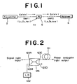
- Fig. 1 is a schematic diagram showing a fundamental constitution of the optical fiber communication system according to the embodiments.
- a transmitter 2 generates signal light by performing modulation on the basis of transmission data.
- the signal light Es thus produced is transmitted as probe light through a first optical fiber SMF1 (length L 1 , dispersion D 1 , nonlinear refractive index n 21 ) and then is inputted to a phase conjugator (PC) 6 disposed in the middle of an entire transmission line.
- the phase conjugator 6 the signal light Es is transformed into phase conjugate light Ec by the use of pump light Eo and is transmitted to a receiver 4 through a second optical fiber SMF2 (length L 2 , dispersion D 2 , nonlinear refractive index n 22 ).
- the receiver 4 receives the phase conjugate light by its photo detector and detects the signal.Such signal detection is performed through, e.g., optical heterodyne detection or direct detection after extraction of the phase conjugate light via a band pass filter, whereby the transmission data is reproduced.
- the optical fiber employed here is a silica fiber for example, and typical one is a 1.3 ⁇ m zero dispersion fiber or a 1.55 ⁇ m dispersion shifted fiber employed generally in light communication.
- the signal light may be one produced by wavelength-division-multiplexing a plurality of signal light outputs obtained from a plurality of signal sources of mutually different wavelength.
- the phase conjugator 6 has a second-order or third-order nonlinear optical medium and a means for supplying signal light and pump light to such a medium. Phase conjugate light is generated by parametric effect in the case of using a second-order nonlinear optical medium, or by degenerate or nondegenerate four-wave mixing (FWM) in the case of using a third-order nonlinear optical medium.
- FWM degenerate or nondegenerate four-wave mixing
- the third-order nonlinear optical medium may be composed of a silica optical fiber for example, and it is possible in this case to generate satisfactory phase conjugate light by selectively presetting the pump light wavelength in FWM approximately to the zero dispersion wavelength of the optical fiber (as disclosed in Japanese Patent Application Hei 5 (1993)-221856 ).
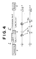
- Fig. 2 is a block diagram of an exemplary phase conjugator.
- This phase conjugator comprises an optical fiber 121 as a nonlinear optical medium, a laser diode 122 as a pump light source, and an optical coupler 123 as an optical means for supplying a combination of the signal light and the pump light to the optical fiber 121.
- the optical fiber 121 is a single mode fiber.
- the wavelength for giving zero dispersion of the optical fiber 121 becomes coincident with the pump light wavelength (oscillation wavelength of the laser diode 122).
- the optical coupler 123 has four ports 123A, 123B, 123C and 123D. To the port 123A is connected the first optical fiber SMF1 shown in Fig. 1 ; to the port 123B is connected the laser diode 122; to the port 123C is connected the first end of the optical fiber 121; and the port 123D is a dead end. Meanwhile the second end of the optical fiber 121 is connected to the second optical fiber SMF2 in Fig. 1 .
- connection signifies operative connection inclusive of optical direct connection and also connection via any optical element such as an optical filter or an optical isolator, and further includes connection after proper adjustment of polarization.
- the optical coupler 123 so functions as to output from the port 123C the light supplied to the ports 123A and 123B.
- This optical coupler 123 may be of fiber fused type or may consist of a half mirror, a wavelength-division multiplexer or a polarized beam splitter.
- the signal light which is supplied to the port 123A of the optical coupler 123, with the pump light supplied to the port 123B thereof, and then to supply the combined light to the optical fiber 121 which is a nonlinear optical medium, hence realizing conversion of the signal light into the phase conjugate light by four-light mixing.
- Fig. 3 is a block diagram of another exemplary phase conjugator.
- this phase conjugator is characterized by the provision of a polarization scrambler 124 disposed between a laser diode 122 and a port 123B of an optical coupler 123.
- a polarization scrambler 124 disposed between a laser diode 122 and a port 123B of an optical coupler 123.
- the polarization state of the light supplied to the first end of the fiber fails to coincide with the polarization state of the light outputted from the second end of the fiber.
- the polarized state of the signal light supplied to the phase conjugator is varied with the lapse of time by environmental changes and so forth.
- the efficiency of conversion from the signal light into the phase conjugate light in the phase conjugator is dependent on the relationship between the polarized state of the signal light and that of the pump light supplied to the phase conjugator.
- the pump light outputted from the laser diode 122 is joined to the signal light via the polarization scrambler 124, so that even if the polarization state of the supplied signal light is varied with the lapse of time, it is still possible to realize stable operations of various optical devices.
- the polarization scrambler 124 has a known ordinary construction including a combination of a 1/2 wavelength plate and a 1/4 wavelength plate, a LiNbO 3 phase modulator and so forth, and when the pump light outputted from the laser diode 122 is substantially linear polarized one for example, the scrambler 124 so functions as to randamize the state of polarization thereof.
- the polarization scrambler 124 is connected to act on the pump light outputted from the laser diode 122.
- the constitution may be so modified that the scrambler is disposed between the port 123A of the optical coupler 123 and the first optical fiber SMF1 shown in Fig. 1 or is incorporated in the transmitter in such a manner as act on the signal light.
- n 2 and A eff stand for the nonlinear refractive index of the fiber and the effective core area thereof respectively, and c stands for the light velocity in a vacuum.
- ⁇ (z), ⁇ 2 (z), ⁇ (z) are functions of z.
- ⁇ z , T A z ⁇ u z , T
- a z ⁇ A 0 ⁇ exp - / 1 2 ⁇ ⁇ 0 z ⁇ ⁇ z ⁇ dz denotes the amplitude, where one case of ⁇ (z)>0 signifies that the transmission line has a loss, and the other case of ⁇ (z) ⁇ 0 signifies that the transmission line has a gain. Meanwhile A(z) ⁇ A(0) signifies that there is no loss.
- A(z) 2 P(z) corresponds to the optical power.
- sgn[ ⁇ 2 ] ⁇ ⁇ 1 takes a value +1 when ⁇ 2 >0 signifying normal dispersion, or takes a value -1 when ⁇ 2 ⁇ 0 signifying anomalous dispersion. If Eq. (9) is established, the complex conjugate thereof is also established, so that the following equation is obtained.
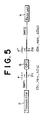
- Fig. 4 In long distance transmission, the transmission line loss is compensated for by repeating with light amplification.
- a phase conjugator is disposed between a transmission line I (length L 1 ) and a transmission line II (length L 2 ).
- u( ⁇ ) obeys evolution equation (9).
- u( ⁇ 0 ) is transformed into the light u*( ⁇ 0 ) by the phase conjugator, and u*( ⁇ ) propagates in the transmission line II ( ⁇ 0 ⁇ 2 ⁇ 0 ) obeying evolution equation (10).
- the compensating condition is that the increment at one of the two positions symmetrical with respect to the phase conjugator is equal to the decrement at the other position.
- Eqs. (18) and (19) represent the requisites for compensation and signify that the total amount of the dispersion and the total amount of the optical Kerr effect in each small section are equal to those in the corresponding small section.
- the above equations signify that the desired compensation can be achieved if the product of the dispersion value, the nonlinear refractive index and the light intensity in each small section of the transmission lines I and II is set to be in inverse proportion to the length of the section and also if the ratio thereof is set to be equalized.
- ⁇ , D and ⁇ are fixed, the following equations can be obtained by integrating Eqs. (18) and (19).
- P 1 P 1 (0)[1-exp(- ⁇ 1 L 1 )]/ ⁇ 1 L 1
- P 2 (L 1 [1-exp(- ⁇ 2 L 2 )]/ ⁇ 2 L 2 denote the average powers in the transmission lines I and II, respectively. These are coincident with the conditions in the method of SPM compensation based on the dispersion compensation and the average value approximation.
- the ratio of the optical Kerr effect to the dispersion value is controlled. Therefore, complete compensation can be realized by giving, at the positions equivalently symmetrical with respect to the phase conjugator, the same ratio of the optical Kerr effect to the dispersion. An increase of this ratio along the transmission line can be attained by gradually decreasing the dispersion or gradually increasing the optical Kerr effect. It is possible to change the dispersion value by adequately designing the fiber. For example, the above ratio is changeable by changing the zero dispersion wavelength of a dispersion shifted fiber (DSF) or by changing the specific refractive index difference between the core and the clad of the fiber or the core diameter thereof.
- DSF dispersion shifted fiber
- an optical fiber applicable to an embodiment of the present invention can be manufactured by continuously changing at least one fiber parameter selected from the loss, nonlinear refractive index, mode field diameter and dispersion.
- a description will be given with regard to a method of changing the light intensity. For instance, an increase of the light intensity along a transmission line having some loss can be attained by gradually decreasing the effective core area A eff . In case the mode field diameter (MFD) is reduced to a half for example, the light intensity is increased approximately four times.
- MFD mode field diameter
- the MFD needs to be further reduced if the loss is greater, any excessive reduction of the MFD causes an increase of the loss on the contrary to consequently fail in achieving satisfactory effect.
- the minimum value of the MFD effective in practical use is at most 2 to 3 ⁇ m. Considering that the MFD of a 1.3 ⁇ m zero dispersion SMF is about 10 ⁇ m and the MFD of a 1.55 ⁇ m DSF is about 8 ⁇ m, it follows that the loss compensable merely by the MFD alone is about 10-14 dB compared with the-SMF or about 8-12 dB compared with the DSF.
- an embodiment of the present invention may be carried out by combining the effect of reducing the core diameter with the effect of decreasing the dispersion value. For example, even in case a further loss of 3 dB is existent, the requisite in Eq.(14) is realizable if the dispersion value can be halved.
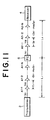
- Fig. 5 shows a first embodiment of the present invention.
- parameters of small sections 1j (length ⁇ z 1j ) and 2j (length ⁇ z 2j ) at positions z 1j and z 2j (defined by Eq.(17)) in transmission lines symmetrical with respect to a phase conjugator 6 are so set as represented by the following equations.
- D 1 ⁇ J ⁇ ⁇ z 1 ⁇ J D 2 ⁇ J ⁇ ⁇ z 2 ⁇ J
- ⁇ I j ⁇ denotes the average intensity in each section. Setting of such average intensity is the same as that already mentioned.
- Fig. 6 shows a second embodiment of the present invention.
- This embodiment represents an exemplary case applied to multistage-repeating transmission employing optical amplifiers.
- another optical fiber SMF1 is virtually divided into N sections, wherein each section has a length of l 1 and the total length is L 1 .
- the optical Kerr effect it is so set as to satisfy the condition of Eq. (23) in the corresponding small sections which are in the sections mutually corresponding with respect to a phase conjugator 6.
- the above setting is executed, in transmission over a repeating section of 50 km, with the optical fiber SMF1 actually or virtually divided at an interval of 500 m. Therefore, if the optical fiber SMF1 employed has a total length of 20 km and is divided by 40 at an interval of 500 m, then it becomes possible to perform transmission over a total length of 2000 km with 39 repeaters each covering 50 km posterior to the phase conjugator 6.
- the division in this example is at equal intervals, the intervals need not be equalized in particular since the requisite is that the conditions of Eqs. (22) and (23) are satisfied with regard to the corresponding sections.
- the requisite regarding the dispersion or power can be alleviated by increasing the distance l 1 , instead of equal-interval division thereof, in accordance with a reduction of the intensity caused by the loss.
- the loss effect can be diminished substantially by dividing each repeating section without fixing the dispersion in such a manner as to relatively increase the dispersion in a high-power portion while relatively decreasing the dispersion in a low-power portion.
- This method renders it possible to alleviate the requirements for the dispersion or power in the optical fiber SMF1.
- the optical fiber SMF2 is used for light-amplified repeating transmission.
- the optical fiber SMF1 is used for light-amplified repeating transmission and thereafter compensation is made in the optical fiber SMF2 by the same method.
- Such an example is shown in Fig. 7 .
- Fig. 7 shows a third embodiment of the present invention.
- the numbers of repeaters anterior and posterior to a phase conjugator 6 are mutually equalized, and the conditions are so set that Eqs. (22) and (23) are satisfied in the sections symmetrical with respect to the phase conjugator 6.
- the loss effect can be diminished substantially by dividing each repeating section without fixing the dispersion in the optical fiber SMF2 in such a manner as to relatively increase the dispersion in a high-power portion while relatively decreasing the dispersion in a low-power portion.
- Fig. 8 shows a fourth embodiment of the present invention.
- the dispersion D 3 of a third optical fiber SMF3 having a length L 3 and disposed between an optical fiber SMF2 and a receiver 4 as shown in Fig. 8 , and the optical Kerr effect n 23 I 3 in such fiber SMF3, are adequately adjusted to thereby realize substantially complete compensation.
- Fig. 9 shows a fifth embodiment of the present invention.
- a plurality of repeaters are provided at positions anterior and posterior to a phase conjugator 6, and the conditions may be so set as to satisfy Eqs. (22) and (23) in the sections mutually corresponding with respect to the phase conjugator 6. More roughly, satisfactory compensation is achievable to a certain extent by setting the conditions in such a manner that the above equations are satisfied with regard to the average value in the entire length, as disclosed in Japanese Patent Application No. Hei 5 (1993)-221856 .
- a third optical fiber SMF3 may be disposed as in the foregoing fourth embodiment of Fig. 8 , and its dispersion D 3 and optical Kerr effect n 23 I 3 may be adequately adjusted.
- the dispersion value proximate to zero dispersion can be changed in accordance with a second-order dispersion inclination (approx. 0.08 ps/nm 2 /km) by changing the wavelength of the signal light.
- an angular, frequency ⁇ C of the phase conjugate light, an angular frequency ⁇ P of pump light and an angular frequency ⁇ S of signal light are in a relationship of 2 ⁇ P - ⁇ S , so that ⁇ C is changeable by changing ⁇ S or ⁇ P .
- Fig. 10 shows a frequency arrangement of signal light, pump light and phase conjugate light to the respective zero dispersion wavelengths ⁇ 10 and ⁇ 20 of optical fibers SMF1 and SMF2. If the dispersion curves of the two fibers are shifted in the same direction by some change of the environment (as indicated by chained lines in Fig. 10 ), ⁇ S and ⁇ C should be shifted in the same direction. However, since ⁇ C is shifted in the reverse direction to any change of ⁇ S , it is desired that, simultaneously with a change of ⁇ S , ⁇ P is also changed in the same direction and by the same value as ⁇ S . In the case of Fig.
- Fig. 11 shows a sixth embodiment of the present invention.
- the dispersion control shown in Fig.7 is executed to alleviate the harmful influence of the power change (deterioration) between light amplifiers. More specifically, each repeating section is divided into several portions, and the dispersion value is gradually decreased in the forward direction of transmission.
- FIG. 12 An example thereof is shown in Fig. 12 .
- Fig. 12 represents an example where each repeating section is divided into three portions, and the dispersion values therein are so set as to become -0.35, -0.30 and -0.25 ps/nm/km respectively in the forward direction of transmission.
- the relay section has a length of 51 km in the above example, then it is divided at an interval of 17 km per portion, so that the dispersion inclination becomes approximately -0.04 dB/km. Therefore, if the fiber loss is -0.20 dB/km, it is possible to reduce the change of the ratio, which is expressed by Eq.
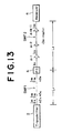
- Fig. 13 shows a seventh embodiment of the present invention.
- This embodiment represents an example where, when it is applied to a light-amplified multi-repeating transmission system, the ratio of the nonlinear effect and dispersion is maintained constant in an optical fiber SMF1.
- the optical fiber SMF1 is virtually divided into a plurality of sections, and the sum of the dispersion value D sj ⁇ z sj in each section j is equalized to the total GVD of the optical fiber SMF2, and further the absolute value ( ⁇ n 21 I sj /D sj ) of the nonlinear effect in each section j is set to be fixed.
- optical fiber SMF2 is performed light-amplified multi-repeating transmission which employs average value approximation, wherein the total of the nonlinear effect in the optical fiber SMF1 is equalized to the total of the average value of the nonlinear effect in the optical fiber SMF2. Also with regard to the optical fiber SMF2, the same setting may be executed as for the optical fiber SMF1.
- the reduction of I Sj resulting from the loss can be compensated by gradually decreasing D 1j , it is possible to keep the ratio of the nonlinear effect and dispertion constant.
- the dispersion value in each section can be kept constant by increasing the length ⁇ 1j of each section in inverse proportion to the loss. That is, the compensation is so made as to keep constant both of n 21 I 1j ⁇ z 1j and D 1j ⁇ z 1j .
- the number of divisions of the optical fiber SMF1 is equal to the number of repeaters in the optical fiber SMF2.
- Fig. 14 shows an eighth embodiment of the present invention.
- the light outputted from a phase conjugator 6 is branched into two by means of an optical coupler 8 or an unshown optical switch, and one branch light is transmitted via an optical fiber SMF2 (length L 2 ) to a receiver 4 (#1) while the other branch light is transmitted via an optical fiber SMF3 (length L 3 ) to another receiver 4 (#2).
- the optical fiber SMF2 is equipped with light amplifiers A2-1, 2, ..., N; and the optical fiber SMF3 is equipped with light amplifiers A3-1, 2, ..., N.
- Fig. 15 shows a ninth embodiment of the present invention.
- a plurality of third fibers are used to perform additional compensation in WDM transmission.
- Denoted by 10 (#1, #2, ..., #N) in this diagram are optical filters for selection of channels with regard to the phase conjugate light transmitted via an optical fiber SMF2.
- the light outputs obtained from the optical filters 10 (#1, #2, ..., #N) are transmitted via compensating optical fibers SMF3-1, 2, ..., N respectively to receivers 4 (#1, #2, ..., #N).
- WDM signal lights E S1 , E S2 , ..., E SN (frequencies: ⁇ S1 , ⁇ S2 , ..., ⁇ SN ) of N channels transmitted via the optical fiber SMF1 are transformed by a phase conjugator 6 into WDM phase conjugate lights E C1 , E C2 , ..., E CN (frequencies: ⁇ C1 , ⁇ C2 , ..., ⁇ CN ) of N channels, which are further transmitted via the optical fiber SMF2 and then are received by the corresponding receivers.
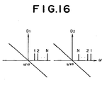
- the channels in the optical fibers SMF1 and SMF2 are so dispersed as illustrated in Fig. 16 .
- signs of dispersion anterior and posterior to the phase conjugator need to be identical, so that the frequency arrangement with respect to zero dispersion becomes such as shown in Fig. 16 .
- the absolute value of the dispersion to the first channel is minimum in the optical fiber SMF1
- the absolute value of the dispersion to the Nth channel is minimum. In principle, therefore, it is difficult to achieve complete dispersion compensation simultaneously for the entire channels.
- frequency selection is executed with regard to each channel after the output of the optical fiber SMF2 is branched, and then additional compensation is executed by the use of third fibers SMF3-1, 2, ..., N which conform to the residual compensation amounts for the individual channels.
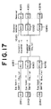
- a tenth embodiment of the present invention shown in Fig. 17 is contrived to execute ideal compensation equally for the entire channels.
- signal lights of respective channels are transmitted via individual fibers SMF11, 12, ..., 1N with the intensities (I 11 , I 12 ,...,I 1N ) conforming to different dispersions.
- the output light of the optical fiber SMF1 is converted into phase conjugate light by phase conjugators 6 (#1), (#2), ..., (#N) of individual channels or by an unshown single phase conjugator for the entire channels, and the light outputs thereof are transmitted via a common optical fiber SMF2 to be received in the same manner as in the foregoing ninth embodiment of Fig. 15 .
- an optical multiplexer for combining a plurality of signal lights or phase conjugate lights is omitted.
- a third optical fiber SMF3 is not necessary here.
- the dispersion and the nonlinear effect in each channel may be set by any of the methods mentioned hereinabove.
- phase conjugator Since the phase conjugator has polarization dependency, its conversion efficiency is different in accordance with the polarized state of signal light, whereby the overall system characteristic is rendered unstable. Furthermore, optical component elements used in the phase conjugator or the light amplifier also have polarization dependency in most cases, so that the signal level is rendered unstable when multiple stages thereof are connected. Such instability can be suppressed by applying polarization diversity or polarization active control, or by executing polarization scrambling for the signal light or pump light. Particularly the method of executing polarization scrambling for the signal light in a transmitter is advantageous due to a simple constitution and in view of elimination of the harmful influence from various kinds of polarization dependency which raise some problems currently in long distance transmission.
- Fig. 18 shows a frequency arrangement in optical phase conjugation where four-wave mixing is employed.
- a gain band is existent in a light amplifier, and therefore it has a frequency ⁇ g which gives a peak of the gain.
- ⁇ g which gives a peak of the gain.
- the number of repeating light amplifiers is small, there is no necessity of taking this gain peak into account.
- the number of such repeaters reaches the order of several tens or hundreds, there occurs narrow-band filtering effect with respect to a specific wavelength.
- this wavelength is in the vicinity of 1558.5 nm.
- the wavelengths of signal light and phase conjugate light are positionally symmetrical with respect to the wavelength of pump light as shown in Fig. 18 , and therefore the gain peak can be ensured over the whole transmission line by shifting the peak wavelength in regard to half the entire light amplifiers.
- an optical filter may be used to eliminate spontaneous emission light from the light amplifier so as to prevent the filtering effect of the light amplifier.
- the optical fiber SMF2 none of optical filter is necessary since the pump light and the signal light passing through the phase conjugator can be eliminated by the filtering effect of the light amplifier, whereby the construction is effectively simplified. It is a matter of course that, instead of utilizing the filtering effect of such EDFA, each repeating amplifier may be equipped with an optical filter to eliminate spontaneous emission light.
- a satisfactory result can be achieved by providing a plurality of band pass filters correspondingly to a plurality of light amplifiers so as to eliminate the spontaneous emission light noise generated in the light amplifiers. It is desired that the pass bands of such band pass filters are so set as to become narrower in accordance with an increase of the distance from the phase conjugator. The reason is based on the following fact.
- the spectrum of the signal component in the output light from the transmitter is the narrowest as it is free from any distortion.
- the signal component is inputted via the first optical fiber to the phase conjugator, its spectrum is most widened as it is affected by the distortion.
- the widened spectrum of the signal component is gradually narrowed in the longitudinal direction of the second optical fiber. Therefore, effective elimination of the noise component is rendered possible by setting the pass band of each band pass filter in the manner mentioned above.
- Fig. 19 shows an eleventh embodiment of the present invention. This embodiment represents an example of utilizing the filtering effect of a light amplifier most efficiently.
- the eleventh embodiment is characterized in the point that a transmitter 2' includes both an optical fiber SMF1 and a phase conjugator 6.
- the optical fiber SMF1 is supplied with signal light outputted from an optical modulator 12.
- the dispersion D 1 of the optical fiber SMF1 is set to be relatively large, whereby the length L 2 of the optical fiber SMF2 can be set to a sufficiently great value, hence realizing long-distance transmission.
- Fig. 20 shows a twelfth embodiment of the present invention.
- a receiver 4' includes both a phase conjugator 6 and an optical fiber SMF2.
- an optical fiber SMF1 serving as a transmission line, there are provided a plurality of loss-compensating light amplifiers A-1, 2, ..., (1-N).
- A-1, 2, ..., (1-N) After arrival at the receiver 4', the repeated signal light is transformed into phase conjugate light by the phase conjugator 6 and then is supplied to a detector 14 via the optical fiber SMF2.
- this embodiment is advantageous for use in an optical WDM transmission system or the like. More specifically, compensation for the waveform distortion can be executed by first changing, in WDM transmission, the frequency of the pump light in the phase conjugator to thereby change the frequency of the phase conjugate light, then performing channel selection by means of an optical filter or the like in the posterior stage, and thereafter transmitting the phase conjugate light via the optical fiber SMF2. If the light is branched into the number of channels anterior or posterior to the phase conjugator 6, the entire channels can be received simultaneously.
- Fig. 21 shows a thirteenth embodiment of the present invention. This embodiment represents an example applied to bidirectional transmission, where there are employed two of the average-approximation transmission systems shown in Fig. 9 .
- a down circuit 16 comprises a transmitter 2A, a receiver 4A, a phase conjugator 6A, an optical fiber SMF11 laid between the transmitter 2A and the phase conjugator 6A, and an optical fiber SMF12 laid between the phase conjugator 6A and the receiver 4A.
- An up circuit 18 comprises a transmitter 2B, a receiver 4B, a phase conjugator 6B, an optical fiber SMF21 laid between the transmitter 2B and the phase conjugator 6B, and an optical fiber SMF22 laid between the phase conjugator 6B and the receiver 4B.
- a plurality of loss-compensating light amplifiers are provided in each of the optical fibers.
- signal light E S1 (frequency ⁇ 1 ) outputted from the transmitter 2A is transmitted after being transformed into phase conjugate light E C1 (frequency ⁇ 2 ) by the phase conjugator 6A.
- signal light E S2 (frequency ⁇ 2 ) outputted from the transmitter 2B is transmitted after being transformed into phase conjugate light E C2 (frequency ⁇ 1 ) by the phase conjugator 6B.
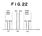
- the entire lights of the frequency ⁇ 1 are transmitted on the left sides of the phase conjugators 6A and 6B in the diagram, while the entire lights of the frequency ⁇ 2 are transmitted on the right sides thereof.
- the signals can be transferred properly if the frequencies are the same. Namely, it is possible to directly apply the technique of turning around a monitor signal or the like executed in ordinary bidirectional transmission.
- the frequency of the down circuit and that of the up circuit are set to be mutually coincident in this embodiment. However, such frequency coincidence is not exactly needed in the down and up circuits if the frequencies are included in the above-described pass bands.
- the condition of ⁇ 1 ⁇ 2 can be satisfied by using a phase conjugator adapted for application of degenerate four-wave mixing, or by connecting an odd number of phase conjugators in series.
- a single bidirectional phase conjugator may be used in common as well.
- the parameters or frequencies in the optical fibers may be set to arbitrary values. In such a case, each phase conjugator need not be disposed at the same position.
- Fig. 23 is a block diagram of a phase conjugator for bidirectional transmission.
- This phase conjugator 60 is disposed, for example, at the middle of each of the down circuit 16 and the up circuit 18 in the system of Fig. 21 . Since the partial configuration relative to the down circuit 16 and that relative to the up circuit 18 are the same, an explanation will be given below merely on the configuration relative to the down circuit 16 alone.
- phase conjugator 60 signal light inputted to the phase conjugator 60 is supplied via optical couplers 20, 22 and 24 to a nonlinear medium 26.
- Phase conjugate light generated in the nonlinear medium 26 is outputted via an optical filter 28, a light amplifier 30 and optical couplers 32 and 34 in this order.
- the optical coupler 20 serves to partially couple the output light of the up circuit 18 to the input light of the down circuit 16.
- the optical coupler 22 partially branches the input light of the down circuit 16, and the branch light is supplied to a photo diode 36.
- the output of the photo diode 36 is supplied to an input monitor circuit 38, whose output is then supplied to both a control circuit 40 and a data signal circuit 44.
- the output of the control circuit 40 and the output of the data signal circuit 44 are supplied to a pump light source 42, whose pump light is supplied via the optical coupler 24 to the nonlinear medium 26.
- a portion of the output light branched by the optical coupler 32 is supplied to a photo diode 46, whose output is then supplied to an APC circuit 48 and an output monitor circuit 50.
- the output of the APC circuit 48 and that of the output monitor circuit 50 are supplied respectively to the pump light source 42 and the data signal circuit 44. Meanwhile a portion of the output light branched by the optical coupler 34 is supplied to the input side of the up circuit 18.
- the input signal light E S1 and the pump light E P1 are optically coupled and supplied to the nonlinear medium 26, whereby phase conjugate light E C1 is generated.
- the phase conjugate light is partially branched and, after photo-electric conversion, the power and the frequency of the pump light source 42 are so controlled that the power of the phase conjugate light is adjusted to a required value.
- Low-degree intensity modulation or frequency modulation is executed to the pump light source 42 by the data signal having the monitor value of the output power, whereby the data signal is superimposed on the phase conjugate light.
- the input signal light is partially branched and, after photoelectric conversion, signal superimposition similar to the above is executed by the data signal having the monitor value of the converted signal, or various control actions are executed by the monitor signal delivered from the transmitting station.
- Such data signals are electrically transferred to or from the up circuit whenever required.
- the output power control may be performed in a form including output control of the light amplifier 30.
- a single phase conjugator is disposed between a transmitter and a receiver.
- longer-distance transmission is rendered possible in a modification where a plurality of the fundamental constitutions of an embodiment except its transmitter and receiver are connected in series, and the transmitter and the receiver are disposed at both ends of such series connection.
- a bidirectional transmission system can be constructed by utilizing the seventh embodiment of Fig. 13 .
- Embodiments are not limited to the details of the above described preferred embodiments.
Landscapes
- Physics & Mathematics (AREA)
- Electromagnetism (AREA)
- Engineering & Computer Science (AREA)
- Computer Networks & Wireless Communication (AREA)
- Signal Processing (AREA)
- Nonlinear Science (AREA)
- Spectroscopy & Molecular Physics (AREA)
- Optical Communication System (AREA)
Claims (29)
- Système de communication à fibres optiques comprenant :une première fibre optique (SMF1) pour transmettre à travers celle-ci un signal de lumière (Es) ; un conjugateur de phase (6) pour générer, en réponse audit signal de lumière fourni par ladite première fibre optique, de la lumière à conjugaison de phase (Ec) correspondant audit signal de lumière ; et une deuxième fibre optique (SMF2) pour transmettre ladite lumière à conjugaison de phase (Ec) délivrée à celle-ci par ledit conjugateur de phase (6) ; dans lequel chacune desdites première et deuxième fibres optiques (SMF1, SMF2) comprend une pluralité de sections telles que le nombre de sections est le même dans chacune des fibres optiques,dans lequel des sections desdites première et deuxième fibres optiques comptées consécutivement depuis ledit conjugateur de phase (6) définissent des sections correspondantes, chacune des sections correspondantes étant constituée d'une première section de ladite première fibre optique et d'une deuxième section de ladite deuxième fibre optique ;
et, pour chacune desdites première et deuxième sections correspondantes :les valeurs moyennes des dispersions chromatiques (Dj) des première et deuxième sections sont déterminées de façon à avoir le même signe ;le produit de la valeur moyenne de la dispersion chromatique dans la première section par la longueur (ΔZj) de la première section est approximativement égal au produit de la valeur moyenne de la dispersion chromatique dans la deuxième section par la longueur (ΔZj') de la deuxième section ; etla valeur moyenne du produit de la fréquence optique (ωj), de l'intensité du signal de lumière (Ij), de l'indice de réfraction non linéaire (nj) et de l'inverse de la dispersion chromatique dans la première section est approximativement égale à la valeur moyenne du produit de la fréquence optique (ωj'), de l'intensité du signal de lumière (Ij'), de l'indice de réfraction non linéaire (nj') et de l'inverse de la dispersion chromatique dans la deuxième section, de sorte qu'une lumière à conjugaison de phase d'un signal de lumière en chaque point de chaque section de la première fibre optique est générée en un point de la deuxième fibre optique correspondant à la section de la première fibre optique. - Système de communication à fibres optiques selon la revendication 1, dans lequel ledit signal de lumière (Es) est un signal de lumière multiplexé par répartition en fréquence obtenu en multiplexant une pluralité de sorties de lumière de fréquences mutuellement différentes.
- Système de communication à fibres optiques selon la revendication 1, dans lequel chacune desdites première et deuxième fibres optiques (SMF1, SMF2) est une fibre en silice.
- Système de communication à fibres optiques selon la revendication 1, dans lequel ledit conjugateur de phase (6) comprend un milieu optique non linéaire (121), une source de lumière de pompage (122) pour générer de la lumière de pompage et un moyen optique (123) pour délivrer la lumière de pompage et le signal de lumière audit milieu optique non linéaire (121).
- Système de communication à fibres optiques selon la revendication 4, dans lequel ledit milieu optique non linéaire (121) présente un effet optique non linéaire du troisième ordre et ladite lumière à conjugaison de phase est générée depuis celui-ci par un mélange de quatre ondes.
- Système de communication à fibres optiques selon la revendication 5, dans lequel ledit milieu optique non linéaire du troisième ordre est une fibre optique et la longueur d'onde de ladite lumière de pompage est approximativement égale à la longueur d'onde de dispersion zéro de ladite fibre optique.
- Système de communication à fibres optiques selon la revendication 4, dans lequel ledit milieu optique non linéaire (121) présente un effet optique non linéaire du deuxième ordre et ladite lumière à conjugaison de phase est générée depuis celui-ci par un effet optique paramétrique.
- Système de communication à fibres optiques selon la revendication 1, comprenant en outre un amplificateur de lumière à compensation de perte (A) disposé au milieu d'au moins une fibre desdites première et deuxième fibres optiques (SMF1, SMF2).
- Système de communication à fibres optiques selon la revendication 8, dans lequel se trouvent une pluralité d'amplificateurs de lumière, et, dans la fibre contenant les amplificateurs, les valeurs absolues de la dispersion chromatique dans les sections situées entre lesdits plusieurs amplificateurs de lumière diminuent progressivement dans la direction de la transmission.
- Système de communication à fibres optiques selon la revendication 1, comprenant en outre un émetteur (2) connecté fonctionnellement à ladite première fibre optique (SMF1) pour générer ledit signal de lumière (Es) en effectuant une modulation en se basant sur les données de transmission ; et un récepteur (4) connecté fonctionnellement à ladite deuxième fibre optique (SMF2) pour reproduire lesdites données de transmission en effectuant une démodulation en se basant sur ladite lumière à conjugaison de phase (Ec).
- Système de communication à fibres optiques selon la revendication 10, comprenant en outre une troisième fibre optique à compensation (SMF3) disposée entre ladite deuxième fibre optique (SMF2) et ledit récepteur (4).
- Système de communication à fibres optiques selon la revendication 8, dans lequel la longueur d'onde de la lumière transmise à travers ledit amplificateur de lumière (A) est approximativement égale à la longueur d'onde de crête de gain dudit amplificateur de lumière.
- Système de communication à fibres optiques selon la revendication 8, dans lequel se trouvent une pluralité d'amplificateurs de lumière, ledit système comprenant en outre une pluralité de filtres passe bande pour éliminer respectivement les bruits de lumière d'émission spontanée provoqués dans ladite pluralité d'amplificateurs de lumière et les bandes passantes respectives de ladite pluralité de filtres passe bande deviennent plus étroites en fonction de l'augmentation de la distance par rapport audit conjugateur de phase (6).
- Système de communication à fibres optiques selon la revendication 4, dans lequel la fréquence dudit signal de lumière et la fréquence de ladite lumière de pompage sont déterminées après des réglages précis exécutés en conformité avec des modifications des caractéristiques de dispersion desdites première et deuxièmes fibres optiques (SMF1, SMF2).
- Système de communication à fibres optiques selon la revendication 1, comprenant en outre un émetteur (2') incluant un moyen (12) pour générer ledit signal de lumière en effectuant une modulation en se basant sur les données de transmission, dans lequel ledit émetteur (2') comporte ladite première fibre optique (SMF1) et ledit conjugateur de phase (6).
- Système de communication à fibres optiques selon la revendication 1, comprenant en outre un récepteur (4') pour effectuer une démodulation en se basant sur ladite lumière à conjugaison de phase (Ec) dans lequel ledit récepteur (4') comporte ledit conjugateur de phase (6) et ladite deuxième fibre optique (SMF2).
- Système de communication à fibres optiques selon la revendication 1, comprenant en outre au moins un trajet optique incluant des éléments correspondant respectivement à ladite première fibre optique (SMF1), audit conjugateur de phase (6) et à ladite deuxième fibre optique (SMF2) ; dans lequel ledit trajet optique est raccordé du côté aval de ladite deuxième fibre optique (SMF2).
- Système de communication à fibres optiques selon la revendication 17, dans lequel ledit trajet optique comporte en outre un amplificateur de lumière.
- Système de communication à fibres optiques selon la revendication 1, dans lequel ledit signal de lumière (Es) est constitué d'une pluralité de faisceaux de signaux de lumière de fréquences mutuellement différentes et une pluralité desdites premières fibres optiques (SMF11, SMF12, ..., SMF1N) et une pluralité desdits conjugateurs de phase (PC-1, PC-2, ..., PC-N) sont respectivement prévues de manière correspondant à ladite pluralité de faisceaux lumineux de signal et un multiplexeur de lumière est prévu en outre pour combiner les sorties desdits plusieurs conjugateurs de phase et pour délivrer la sortie combinée à ladite deuxième fibre optique (SMF2).
- Système de communication à fibres optiques selon la revendication 1, dans lequel ledit signal de lumière (Es) est constitué d'une pluralité de faisceaux de signaux de lumière de fréquences mutuellement différentes et une pluralité desdites premières fibres optiques sont prévues de manière correspondant à ladite pluralité de faisceaux de signaux de lumière et un multiplexeur de lumière est prévu en outre pour combiner les sorties desdites plusieurs premières fibres optiques et pour délivrer la sortie combinée audit conjugateur de phase (6).
- Système de communication à fibres optiques selon la revendication 1, dans lequel les fréquences dudit signal de lumière (Es) et de ladite lumière conjuguée en phase (Ec) sont fixées de façon à produire une dispersion normale dans lesdites première et deuxième fibres optiques (SMF1, SMF2).
- Système de communication à fibres optiques selon la revendication 1, comprenant en outre un embrouilleur de polarisation destiné à agir sur ledit signal de lumière.
- Système de communication à fibres optiques selon la revendication 1, dans lequel ledit conjugateur de phase comporte un milieu optique non linéaire (121), une source de lumière de pompage (122) pour générer de la lumière de pompage et un moyen optique (123) pour délivrer ladite lumière de pompage et ledit signal de lumière audit milieu optique non linéaire (121) ; et un embrouilleur de polarisation (124) est prévu en outre pour agir sur ladite lumière de pompage.
- Système de communication à fibres optiques bidirectionnel équipé d'un circuit de montée (18) et d'un circuit de descente (16) comportant chacun le système de communication à fibres optiques défini dans la revendication 1.
- Système de communication à fibres optiques bidirectionnel selon la revendication 24, dans lequel la fréquence du signal de lumière (Es) dans ledit circuit de descente (16) et la fréquence de la lumière à conjugaison de phase (Ec) dans ledit circuit de montée (18) sont approximativement égales l'une à l'autre et la fréquence de la lumière à conjugaison de phase (Ec) dans ledit circuit de descente (16) et la fréquence du signal de lumière (Es) dans ledit circuit de montée (18) sont approximativement égales l'une à l'autre.
- Système de communication à fibres optiques bidirectionnel selon la revendication 24, comprenant en outre un moyen (60) pour transférer un signal entre ledit circuit de descente et ledit circuit de montée.
- Fibre optique destinée à être utilisée en tant que dite première ou deuxième fibre optique dans un système de communication selon la revendication 1.
- Fibre optique selon la revendication 27, dans laquelle les conditions définies dans la revendication 1 sont sensiblement satisfaites par une pluralité de fibres fondues et mutuellement raccordées.
- Fibre optique selon la revendication 27, dans lequel les conditions définies dans la revendication 1 sont sensiblement satisfaites par au moins un paramètre de fibre variant en continu dans la direction longitudinale, l'au moins un paramètre de fibre étant choisi parmi l'affaiblissement, l'indice de réfraction non linéaire, le diamètre de champ de mode et la dispersion.
Applications Claiming Priority (6)
| Application Number | Priority Date | Filing Date | Title |
|---|---|---|---|
| JP255849/94 | 1994-10-20 | ||
| JP25584994 | 1994-10-20 | ||
| JP25584994 | 1994-10-20 | ||
| JP4457495 | 1995-03-03 | ||
| JP44574/95 | 1995-03-03 | ||
| JP04457495A JP3494738B2 (ja) | 1994-10-20 | 1995-03-03 | 光位相共役を用いた光ファイバ通信システム |
Publications (3)
| Publication Number | Publication Date |
|---|---|
| EP0708538A2 EP0708538A2 (fr) | 1996-04-24 |
| EP0708538A3 EP0708538A3 (fr) | 2000-10-25 |
| EP0708538B1 true EP0708538B1 (fr) | 2010-04-28 |
Family
ID=26384522
Family Applications (1)
| Application Number | Title | Priority Date | Filing Date |
|---|---|---|---|
| EP19950115698 Expired - Lifetime EP0708538B1 (fr) | 1994-10-20 | 1995-10-05 | Système de communication à fibres optiques utilisant la conjugaison de phase optique |
Country Status (3)
| Country | Link |
|---|---|
| EP (1) | EP0708538B1 (fr) |
| JP (1) | JP3494738B2 (fr) |
| DE (1) | DE69536073D1 (fr) |
Families Citing this family (9)
| Publication number | Priority date | Publication date | Assignee | Title |
|---|---|---|---|---|
| DE69739862D1 (de) * | 1996-08-22 | 2010-06-10 | Fujitsu Ltd | Faseroptisches Übertragungssystem mit optischer Phasenkonjugation |
| JPH11243374A (ja) | 1998-02-26 | 1999-09-07 | Fujitsu Ltd | 光信号伝送システム及び、これに用いる光信号伝送装置 |
| FI108488B (fi) * | 1999-03-12 | 2002-01-31 | Nokia Corp | Optisessa tiedonsiirtoverkossa toteutettava dispersion kompensointi ja optinen tiedonsiirtoverkko |
| JP3784585B2 (ja) | 1999-08-26 | 2006-06-14 | 富士通株式会社 | 光ファイバ伝送のための方法、光デバイス及びシステム |
| DE10012881B4 (de) | 2000-03-16 | 2008-09-04 | Nokia Siemens Networks Gmbh & Co.Kg | Ramanverstärkeranordnung |
| JP5027434B2 (ja) | 2006-03-28 | 2012-09-19 | 富士通株式会社 | 光信号の波形を整形する装置 |
| US8160240B2 (en) | 2008-05-28 | 2012-04-17 | Microsemi Semiconductor (U.S.) Inc. | Echo cancellation balance using noise generator and average power detection |
| JP5381089B2 (ja) | 2008-12-25 | 2014-01-08 | 富士通株式会社 | 光信号処理装置 |
| CN110274885B (zh) * | 2019-07-03 | 2022-04-05 | 西安文理学院 | 宽谱带时间分辨吸收光谱单次测量装置 |
Family Cites Families (1)
| Publication number | Priority date | Publication date | Assignee | Title |
|---|---|---|---|---|
| US5365362A (en) * | 1993-09-10 | 1994-11-15 | At&T Bell Laboratories | Ultra-high capacity non-soliton optical transmission using optical phase conjugation |
-
1995
- 1995-03-03 JP JP04457495A patent/JP3494738B2/ja not_active Expired - Fee Related
- 1995-10-05 EP EP19950115698 patent/EP0708538B1/fr not_active Expired - Lifetime
- 1995-10-05 DE DE69536073T patent/DE69536073D1/de not_active Expired - Lifetime
Also Published As
| Publication number | Publication date |
|---|---|
| JPH08171102A (ja) | 1996-07-02 |
| EP0708538A2 (fr) | 1996-04-24 |
| JP3494738B2 (ja) | 2004-02-09 |
| EP0708538A3 (fr) | 2000-10-25 |
| DE69536073D1 (de) | 2010-06-10 |
Similar Documents
| Publication | Publication Date | Title |
|---|---|---|
| EP0776103B1 (fr) | Système de communication utilisant la conjugation de phase optique | |
| EP0987583B1 (fr) | Appareil de conjugaison de phase insensible à la polarisation et système comprenant un tel appareil | |
| EP0703680B1 (fr) | Appareil et procédé de compensation de dispersion chromatique résultant de conjugaison de phase optique, ou conversion électro-optique d'autre type | |
| JP3494661B2 (ja) | 光位相共役を用いた光ファイバ通信システム並びに該システムに適用可能な装置及びその製造方法 | |
| US5365362A (en) | Ultra-high capacity non-soliton optical transmission using optical phase conjugation | |
| US6160942A (en) | Optical fiber communication system using optical phase conjugation | |
| EP0708538A2 (fr) | Système de communication à fibres optiques utilisant la conjugaison de phase optique | |
| US7218807B2 (en) | Optical transmission system using an optical phase conjugation device | |
| JP4056933B2 (ja) | 光位相共役を用いた光ファイバ通信システム並びに該システムに適用可能な装置及びその製造方法 | |
| EP1576747B1 (fr) | Systeme de transmission optique mettant en oeuvre un dispositif de conjugaison de phase optique | |
| JP3913804B2 (ja) | 光位相共役を用いた光ファイバ通信システム | |
| JP4008484B2 (ja) | 光位相共役を用いた光ファイバ通信システム | |
| JP4057042B2 (ja) | 光位相共役を用いた光ファイバ通信システム | |
| JP4008483B2 (ja) | 光位相共役を用いた光ファイバ通信システム | |
| JP4008482B2 (ja) | 光位相共役を用いた光ファイバ通信システム |
Legal Events
| Date | Code | Title | Description |
|---|---|---|---|
| PUAI | Public reference made under article 153(3) epc to a published international application that has entered the european phase |
Free format text: ORIGINAL CODE: 0009012 |
|
| AK | Designated contracting states |
Kind code of ref document: A2 Designated state(s): DE FR GB |
|
| PUAL | Search report despatched |
Free format text: ORIGINAL CODE: 0009013 |
|
| RIC1 | Information provided on ipc code assigned before grant |
Free format text: 7H 04B 10/18 A, 7G 02F 1/35 B |
|
| AK | Designated contracting states |
Kind code of ref document: A3 Designated state(s): DE FR GB |
|
| 17P | Request for examination filed |
Effective date: 20001025 |
|
| 17Q | First examination report despatched |
Effective date: 20070828 |
|
| GRAP | Despatch of communication of intention to grant a patent |
Free format text: ORIGINAL CODE: EPIDOSNIGR1 |
|
| GRAS | Grant fee paid |
Free format text: ORIGINAL CODE: EPIDOSNIGR3 |
|
| GRAA | (expected) grant |
Free format text: ORIGINAL CODE: 0009210 |
|
| AK | Designated contracting states |
Kind code of ref document: B1 Designated state(s): DE FR GB |
|
| REG | Reference to a national code |
Ref country code: GB Ref legal event code: FG4D |
|
| REF | Corresponds to: |
Ref document number: 69536073 Country of ref document: DE Date of ref document: 20100610 Kind code of ref document: P |
|
| PGFP | Annual fee paid to national office [announced via postgrant information from national office to epo] |
Ref country code: FR Payment date: 20100915 Year of fee payment: 16 |
|
| PGFP | Annual fee paid to national office [announced via postgrant information from national office to epo] |
Ref country code: DE Payment date: 20101019 Year of fee payment: 16 |
|
| PLBE | No opposition filed within time limit |
Free format text: ORIGINAL CODE: 0009261 |
|
| STAA | Information on the status of an ep patent application or granted ep patent |
Free format text: STATUS: NO OPPOSITION FILED WITHIN TIME LIMIT |
|
| PGFP | Annual fee paid to national office [announced via postgrant information from national office to epo] |
Ref country code: GB Payment date: 20101026 Year of fee payment: 16 |
|
| 26N | No opposition filed |
Effective date: 20110131 |
|
| REG | Reference to a national code |
Ref country code: FR Ref legal event code: ST Effective date: 20120629 |
|
| PG25 | Lapsed in a contracting state [announced via postgrant information from national office to epo] |
Ref country code: DE Free format text: LAPSE BECAUSE OF NON-PAYMENT OF DUE FEES Effective date: 20120501 |
|
| REG | Reference to a national code |
Ref country code: DE Ref legal event code: R119 Ref document number: 69536073 Country of ref document: DE Effective date: 20120501 |
|
| PG25 | Lapsed in a contracting state [announced via postgrant information from national office to epo] |
Ref country code: FR Free format text: LAPSE BECAUSE OF NON-PAYMENT OF DUE FEES Effective date: 20111102 |
|
| GBPC | Gb: european patent ceased through non-payment of renewal fee |
Effective date: 20121005 |
|
| PG25 | Lapsed in a contracting state [announced via postgrant information from national office to epo] |
Ref country code: GB Free format text: LAPSE BECAUSE OF NON-PAYMENT OF DUE FEES Effective date: 20121005 |