EP0709328A2 - Walze mit zwei Reibungsbeiwerten - Google Patents
Walze mit zwei Reibungsbeiwerten Download PDFInfo
- Publication number
- EP0709328A2 EP0709328A2 EP95116894A EP95116894A EP0709328A2 EP 0709328 A2 EP0709328 A2 EP 0709328A2 EP 95116894 A EP95116894 A EP 95116894A EP 95116894 A EP95116894 A EP 95116894A EP 0709328 A2 EP0709328 A2 EP 0709328A2
- Authority
- EP
- European Patent Office
- Prior art keywords
- roller
- traction
- web
- coefficient
- rollers
- Prior art date
- Legal status (The legal status is an assumption and is not a legal conclusion. Google has not performed a legal analysis and makes no representation as to the accuracy of the status listed.)
- Withdrawn
Links
- 230000009977 dual effect Effects 0.000 title abstract description 6
- 230000037303 wrinkles Effects 0.000 abstract description 21
- 230000035945 sensitivity Effects 0.000 abstract description 4
- 238000005461 lubrication Methods 0.000 description 19
- 238000000034 method Methods 0.000 description 8
- 230000008569 process Effects 0.000 description 8
- 239000000463 material Substances 0.000 description 7
- 230000007547 defect Effects 0.000 description 6
- 235000019592 roughness Nutrition 0.000 description 6
- 235000019587 texture Nutrition 0.000 description 6
- 238000012360 testing method Methods 0.000 description 5
- 238000013461 design Methods 0.000 description 4
- 230000000694 effects Effects 0.000 description 3
- 239000010408 film Substances 0.000 description 3
- 239000011888 foil Substances 0.000 description 3
- 238000004519 manufacturing process Methods 0.000 description 3
- 230000007480 spreading Effects 0.000 description 3
- 238000003892 spreading Methods 0.000 description 3
- 238000005299 abrasion Methods 0.000 description 2
- 230000009471 action Effects 0.000 description 2
- 230000008859 change Effects 0.000 description 2
- 230000007423 decrease Effects 0.000 description 2
- 230000003247 decreasing effect Effects 0.000 description 2
- 239000004744 fabric Substances 0.000 description 2
- 239000000123 paper Substances 0.000 description 2
- 230000007704 transition Effects 0.000 description 2
- 239000000853 adhesive Substances 0.000 description 1
- 230000001070 adhesive effect Effects 0.000 description 1
- 239000002390 adhesive tape Substances 0.000 description 1
- 238000013459 approach Methods 0.000 description 1
- 238000005452 bending Methods 0.000 description 1
- 230000008901 benefit Effects 0.000 description 1
- 239000011248 coating agent Substances 0.000 description 1
- 238000000576 coating method Methods 0.000 description 1
- 239000002131 composite material Substances 0.000 description 1
- 229910003460 diamond Inorganic materials 0.000 description 1
- 239000010432 diamond Substances 0.000 description 1
- 238000002474 experimental method Methods 0.000 description 1
- 239000012530 fluid Substances 0.000 description 1
- 239000004519 grease Substances 0.000 description 1
- 238000012423 maintenance Methods 0.000 description 1
- 238000005259 measurement Methods 0.000 description 1
- 239000002994 raw material Substances 0.000 description 1
- 239000004576 sand Substances 0.000 description 1
- 238000005488 sandblasting Methods 0.000 description 1
- 230000003746 surface roughness Effects 0.000 description 1
- 239000010409 thin film Substances 0.000 description 1
- 238000011144 upstream manufacturing Methods 0.000 description 1
- 230000037330 wrinkle prevention Effects 0.000 description 1
Images

Classifications
-
- B—PERFORMING OPERATIONS; TRANSPORTING
- B65—CONVEYING; PACKING; STORING; HANDLING THIN OR FILAMENTARY MATERIAL
- B65H—HANDLING THIN OR FILAMENTARY MATERIAL, e.g. SHEETS, WEBS, CABLES
- B65H27/00—Special constructions, e.g. surface features, of feed or guide rollers for webs
-
- B—PERFORMING OPERATIONS; TRANSPORTING
- B65—CONVEYING; PACKING; STORING; HANDLING THIN OR FILAMENTARY MATERIAL
- B65H—HANDLING THIN OR FILAMENTARY MATERIAL, e.g. SHEETS, WEBS, CABLES
- B65H2404/00—Parts for transporting or guiding the handled material
- B65H2404/10—Rollers
- B65H2404/18—Rollers composed of several layers
- B65H2404/181—Rollers composed of several layers with cavities or projections at least at one layer
-
- B—PERFORMING OPERATIONS; TRANSPORTING
- B65—CONVEYING; PACKING; STORING; HANDLING THIN OR FILAMENTARY MATERIAL
- B65H—HANDLING THIN OR FILAMENTARY MATERIAL, e.g. SHEETS, WEBS, CABLES
- B65H2404/00—Parts for transporting or guiding the handled material
- B65H2404/50—Surface of the elements in contact with the forwarded or guided material
- B65H2404/52—Surface of the elements in contact with the forwarded or guided material other geometrical properties
- B65H2404/521—Reliefs
- B65H2404/5211—Reliefs only a part of the element in contact with the forwarded or guided material
Definitions
- the present invention relates to rollers. More particularly, the present invention relates to rollers that provide a constant traction to eliminate web slippage and scratches.
- a continuous sheet of paper, film, foil, non-woven, or woven material is transported through one or more processes to convert or rewind the material.
- Web handling is used in manufacturing adhesive tapes, magnetic tapes, printed products, abrasive products, medical tapes, medical drapes, face masks, photographic films and papers, reflective sheeting, fabrics, foils and other products.
- each roller typically has three components: a shaft, a shell, and bearings.
- the surface material and texture of the shell is an important part of its design.
- the combination of the friction and the lubrication between the web and roller, called traction, is determined by the operating conditions and the two surfaces involved. Control of the web requires traction forces between the web and rollers.
- An idler roller can scratch the web when the roller surface speed is less than the web surface speed. This occurs when the force to turn the roller is greater than the force available from the web-to-roller friction. Slip and scratches often occur as the speed increases in a web handling process. As speed increases the force to turn or accelerate the roller increases.
- Figure 1 shows a comparison of the web speed and the torques. The torque required (T R ) to turn the roller and the torque available (T A ) to drive the roller are compared. The torque required increases with increasing speed and the torque available decreases with increasing speed. The roller will slip at a speed S when the driving torque available is less than the torque required to turn the roller, shown as the intersection of the two curves.
- any body in motion through a fluid develops a boundary layer.
- an air boundary layer develops near to the web's surface and moves with the web.
- the air layer reduces friction between the roller and the web.
- the air layer thickness is a function of roller radius, air viscosity, velocity, and tension, and the thickness and lubrication effects increase with increased speed, increased radius, and decreased tension.
- the air layer increases and floats the web off the roller.
- the tensioned web wrapped around a roller develops a pressure which will compress the air layer between the web and roller. This pressure decreases with increased radius and decreased tension.
- a transition from high to low traction occurs when the air layer thickness overcomes the combined roughness of the web and roller surfaces.
- the high to low traction transition can be shifted with increases in web or roller roughness.
- Large air layers of high speed, low tension web handling (greater than 152.4 m/min (500 ft/min), less than 1.75 N/cm (1 lb/in) require roller design changes to maintain good traction.
- Roughened or textured roller surfaces are effective in improving high speed traction.
- a textured surface allows the air to escape from between the web and roller.
- Figure 1 shows that adding texture to a roller, such as by grooving or knurling, will reduce slip by preventing lubrication, keeping the available torque (T A,T ) greater than the required turning torque.
- roller roughness patterns can be used including: spiral grooved (herringbone pattern); dual spiral grooved (diamond pattern); plasma sputtered; sand blasted; knurled; and various machined roughnesses.
- Grooves cut into the surface of a roller may not be sufficient to prevent air lubrication. If the spacing between grooves is greater than 2.5 cm (1 in) and the surface roughness between the grooves is smooth, the web will float between the grooves without significantly preventing lubrication. An overall roughness, like knurling, sand blasting, or plasma coating, is the best way to eliminate air lubrication problems.
- the traction between a web and roller is an important condition which determines if a web will wrinkle on the roller.
- a roller is naturally a wrinkle prevention device because webs do not easily buckle or bend in two directions at once. This is the concept of shape stiffening. As a web bends to conform to the cylindrical shape of the roller it will gain stiffness or resistance to buckling in the crossweb direction. A web can buckle in the upstream web span as it approaches a roller and then lay flat with no wrinkle on the roller. What determines whether a wrinkle will form is the web-to-roller traction. If the web-to-roller traction is high, the buckled web approaching a roller will be unable to slide laterally to a wrinkleless shape. If the web to roller traction is low, the web will slide laterally and not wrinkle.
- rollers and bearings attempt to improve web handling.
- air bearings replace standard oil or grease ball bearings to greatly reduce the force required to drive a roller. This addresses slip and scratch problems but does nothing for wrinkle sensitivity.
- the Vacutex roller by Pagendarm reduces slip and scratches in low wrap roller positions.
- the Vacutex roller combines a roller bearing system with an air nozzle system.
- a live shaft roller is mounted in the cradle of two wheels using a shaft and wheel arrangement to create a mechanical advantage of greater than fifty to one.
- This bearing system reduces the force required to drive a roller.
- the nozzle system creates a Coanda effect suction and increases the wrap and force of the web on the roller. Similar to air bearings, this device reduces slip and scratch defects, but will not aid wrinkle sensitivity.
- the bowed roller is banana-shaped with a constant diameter and a curved shaft or axis of rotation. It is formed as a series of narrow rollers stacked next to each other on a curved shaft. An expandable elastomeric cover is stretched over the rollers to form a continuous, wide surface.
- the bowed roller spreads the web based on the web tracking rule of normal entry, where each lane of web attempts to enter the downstream roller perpendicular to the axis of rotation. Since the rotation of the bowed roller causes the center of the web to track straight and each edge to track laterally, it results in a laterally taut, wrinkle-free web.
- the percent the web spreads can be calculated from span length, wrap angle, web width, and bow depth.
- Both reverse crown and tape bumpered rollers feature a crossweb roller diameter variation where the diameter of the roller is greater at the edges than at the center. These rollers require good traction, no-slip conditions between the web and roller. The large diameter edges change the web tension crossweb profile entering the roller with higher tension at the edges than at the center. This creates a moment in each side of the web. The opposite moments cause the web to spread as is enters the downstream roller. These rollers have similar disadvantages as bowed rollers.
- Edge puller nips are used extensively in the fabric industry for low modulus webs. Two narrow rollers are nipped together with a spring loading. The nips grip the web span between rollers. The web develops traction to these nips and will attempt to follow the normal entry rule. If the nips are angled outwardly, the web will spread laterally. These nips are difficult to use with high modulus materials, require two-sided contact, and can damage crush-sensitive webs.
- the Flex spreader by Bingham and the Arco-Stretcher by American Roller are two bevel-grooved rubber covered spreaders.
- the surface of these rollers flexes as the web tension presses down.
- the individual spiral fins created by the grooves flex laterally, and pull the web taut in the width direction.
- These rollers have a nearly straight cylinder and gentle spreading action, but cannot be used in contact with an adhesive-coated side of a web, have limited spreading, and allow thin webs to fall into the grooves.
- a "D” bar is a bent bar or crowned cylinder which the web is dragged over to increase the path length and the tension of the center of the moving web. Tightening the center of the web creates lateral bending from the center to the edge and reduces wrinkles. This device requires the web to slip on the "D" bar and is not used on scratch sensitive products.
- Expander rollers expand and contract laterally during each revolution.
- the web is wrapped around the circumference of expander roller for part or all of the 180 degrees of lateral expansion.
- the WrinkleStop roller, the Polyband roller and the Menzel roller are expander type rollers.
- WrinkleStop rollers manufactured by Converter Accessories Corp., are similar to bowed rollers. Segments rotating on a shaft support a flexible sleeve or covering. However, the WrinkleStop roller is cylindrical, not bowed. The spreading action is created by angling the end plates of the sleeve. The web bonds to the elastomeric surface and is spread laterally as the roller rotates.
- Polyband expander rollers originally manufactured by Lembo, are similar to the WrinkleStop and other expander rollers. Several polymeric bands, similar to surgical tubing, are stretched between two angled end plates. The web wraps the roller on the band expanding side, pulling out wrinkles. Polyband rollers are limited to speeds of one thousand rpm due to centrifugal forces. These rollers usually are high drag torque devices requiring high web tension or torque assist motors and their complex design has high maintenance costs.
- the present invention is a roller surface that handles a web without slip or scratch defects and does so over a wide range of web tensions, web speeds, and roller diameters.
- the present invention is also a roller having this surface.
- the roller surface can have a plurality of surfaces each having a coefficient of traction that differs from the coefficient of traction of the adjacent surface.
- the plurality of surfaces can form axial or circumferential stripes. Three circumferential surfaces can be formed, with the axial center surface having a high coefficient of traction and the axial end surfaces having lower coefficients of traction. Alternatively, the axial center surface can have a low coefficient of traction with the axial end surfaces having lower coefficients of traction. The axial end surfaces can have equal coefficients of traction.
- Figure 1 is a graph comparing the web speed, the torque required to turn the roller, and the torque available to drive the roller.
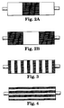
- Figure 2A is a plan view of a roller surface of the present invention.
- Figure 2B is a plan view of a roller surface of another embodiment of the present invention.
- Figure 3 is a plan view of a roller surface of another embodiment of the present invention.
- Figure 4 is a plan view of a roller surface of another embodiment of the present invention.
- Figure 5 is an enlarged cross-sectional view of a preferred knurl pattern.
- Figure 6 graphs two variations of the roller compared to a 100% smooth or 100% rough roller surface.
- the present invention is a roller and roller surface used to transport a moving web or other flexible, continuous sheet of material such as paper, film, foil, non-woven, woven, composite or laminate of these materials, in coated or uncoated forms.
- the surface can be applied to idler rollers driven by the web, whether stationary or part of a moving apparatus, and driven rollers powered by speed or torque control.
- the roller combines low traction portions (surfaces having a low coefficient of traction) which prevent wrinkle problems and high traction portions (surfaces having a high coefficient of traction) which prevent slip problems.
- the different surfaces are shown in Figures 2-4.
- One embodiment combines a high traction, rough surface in the center 25-50% of the roller contact width, and low traction, smooth surfaces on the ends, as shown in Figure 2A.
- a low traction, smooth surface can be located in the center of the roller with a high traction, rough surface on the ends.
- Figures 3 and 4 show alternative embodiments of using both high and low traction surfaces.
- a plurality of circumferential rough and smooth stripes are used and in Figure 4, a plurality of axial rough and smooth stripes are used.
- embodiments with various surfaces having three or more different coefficients of traction can be used.
- the preferred rough surface for thin film applications is a knurl pattern, as shown in Figure 5.
- the distance a between the centers of adjacent knurl grooves is 0.25 cm (0.1in).
- the height of the knurls is less than 0.025 cm (0.010 in).
- This knurl pattern prevents air lubrication traction losses at typical high speeds of 152.4-609.6 m/min (500-2000 ft/min) and low tensions of 0.44-1.75 N/cm (0.25-1.0 lb/in) found in many converting processes.
- the knurled surface is preferred for ease of cleanup and reduced traction changes due to abrasion.
- Variations of a dual traction roller surface can he designed with different materials, textures, or geometric patterns.
- One geometric surface pattern has a simple, laterally changing, high traction center which is easy to machine.
- Other patterns resulting in a percentage split of low and high traction surfaces include radial striping, lateral striping, and low traction center patterns.
- the coefficient of traction (COT) for web-to-roller cases uses the belt equation to describe the relationship of the coefficient of friction to a wrapped cylindrical surface (the roller).
- a simple test determines T high . The test requires a non-rotating roller, a strip of web, a weight, and a force-measuring spring scale.
- Direct coefficient of traction measurement can also be performed by measuring the force on the web using tension transducer rollers.
- the web is threaded through a three roller system; the first is a force-measuring roller, the second is a roller with the surface to be tested, and the third is another force-measuring roller.
- the torque of a brake connected to the second roller increases until that roller slips.
- the two force-measuring rollers measure the T high and T low for the selected process conditions.
- the results will be similar to the belt equation test.
- air lubrication effects are seen and the calculated m value is the coefficient of traction.
- the average coefficient of traction can be any value between the coefficient of traction of the low traction surface, and the coefficient of traction of the high traction surface.
- Figure 6 is a graph showing two variations of the roller compared to the single surface extremes of a 100% smooth or 100% rough roller surface.
- the fully smooth roller lubricates quickly and can not overcome bearing drag at less than 152.4 m/min (500 ft/min).
- the fully rough roller with 100 percent knurled surface did not show any significant air lubrication up to 457.2 m/min (1500 ft/min).
- the roller surface of the present invention creates a constant traction value over a wide operating range 152.4-457.2 m/min (500-1500 ft/min).
- the 50 percent rough version has a traction coefficient which is half way between no lubrication and full lubrication.
- the 25 percent rough version has a traction coefficient which is one quarter of the way between no lubrication and full lubrication traction.
Landscapes
- Registering, Tensioning, Guiding Webs, And Rollers Therefor (AREA)
Applications Claiming Priority (2)
| Application Number | Priority Date | Filing Date | Title |
|---|---|---|---|
| US33031794A | 1994-10-27 | 1994-10-27 | |
| US330317 | 1994-10-27 |
Publications (2)
| Publication Number | Publication Date |
|---|---|
| EP0709328A2 true EP0709328A2 (de) | 1996-05-01 |
| EP0709328A3 EP0709328A3 (de) | 1997-08-27 |
Family
ID=23289226
Family Applications (1)
| Application Number | Title | Priority Date | Filing Date |
|---|---|---|---|
| EP95116894A Withdrawn EP0709328A3 (de) | 1994-10-27 | 1995-10-26 | Walze mit zwei Reibungsbeiwerten |
Country Status (2)
| Country | Link |
|---|---|
| EP (1) | EP0709328A3 (de) |
| JP (1) | JPH08208088A (de) |
Cited By (7)
| Publication number | Priority date | Publication date | Assignee | Title |
|---|---|---|---|---|
| WO1999062804A1 (en) * | 1998-05-18 | 1999-12-09 | Valmet Corporation | Reel-up of a paper web and cylinder thereof |
| JP2010143712A (ja) * | 2008-12-18 | 2010-07-01 | Hirano Tecseed Co Ltd | ロールの製造方法 |
| US20170190452A1 (en) * | 2015-12-30 | 2017-07-06 | Adam W. Duncan | Shrink sleeve applicator and related roller conveyor arrangement |
| CN107892200A (zh) * | 2017-08-16 | 2018-04-10 | 住华科技股份有限公司 | 导辊装置 |
| WO2020074227A1 (de) * | 2018-10-12 | 2020-04-16 | TRüTZSCHLER GMBH & CO. KG | Walze für eine faserbandtransportvorrichtung und damit ausgestattete faserbandtransportvorrichtung |
| WO2021183715A1 (en) * | 2020-03-12 | 2021-09-16 | Cryovac, Llc | Systems and methods for handling a flexible web |
| CN115485146A (zh) * | 2020-03-12 | 2022-12-16 | 克里奥瓦克公司 | 用于打印柔性幅材的系统和方法以及打印组合物 |
Families Citing this family (6)
| Publication number | Priority date | Publication date | Assignee | Title |
|---|---|---|---|---|
| JP2008062238A (ja) * | 2007-12-14 | 2008-03-21 | Hirano Tecseed Co Ltd | ガイドロール |
| JP2008063150A (ja) * | 2007-12-14 | 2008-03-21 | Hirano Tecseed Co Ltd | ウエブの蛇行修正装置 |
| JP2009298496A (ja) * | 2008-06-10 | 2009-12-24 | Toyota Motor Corp | 搬送ローラおよび膜電極接合体の製造装置、製造方法 |
| JP5649853B2 (ja) * | 2010-05-26 | 2015-01-07 | 株式会社ヒラノテクシード | ガイドロール |
| JP5635031B2 (ja) * | 2012-03-27 | 2014-12-03 | ヒラノ技研工業株式会社 | 皺取り装置 |
| NL2028931B1 (en) * | 2021-08-05 | 2023-02-17 | Vmi Holland Bv | Packaging device and method for packaging discrete medicaments in pouches |
Family Cites Families (8)
| Publication number | Priority date | Publication date | Assignee | Title |
|---|---|---|---|---|
| DE2357208C3 (de) * | 1973-11-16 | 1981-05-14 | Albert-Frankenthal Ag, 6710 Frankenthal | Zugwalzenpaar für eine Rotationsmaschine zum Transportieren von Papierbahnen |
| JPS609898Y2 (ja) * | 1976-12-10 | 1985-04-05 | ロ−レルバンクマシン株式会社 | 紙葉類繰出しロ−ラ |
| US4560154A (en) * | 1982-12-28 | 1985-12-24 | Musashi Engineering Kabushiki Kaisha | Paper sheet feed-out device for a paper sheet counting apparatus |
| DE3545295C1 (de) * | 1985-12-20 | 1986-10-16 | M.A.N.- Roland Druckmaschinen AG, 6050 Offenbach | Zugwalzenpaar fuer eine Rotationsdruckmaschine zum Transportieren von Bedruckstoffbahnen |
| JPH0295661A (ja) * | 1988-09-29 | 1990-04-06 | Roorutetsuku:Kk | ローラ装置 |
| US4917283A (en) * | 1989-02-27 | 1990-04-17 | Weatherhead Franklin L | Strip feed roller |
| JPH05124761A (ja) * | 1991-10-31 | 1993-05-21 | Sony Corp | ガイドロール装置 |
| US5267008A (en) * | 1991-12-23 | 1993-11-30 | Xerox Corporation | Friction retard feeder with a composite feed element |
-
1995
- 1995-10-20 JP JP27263195A patent/JPH08208088A/ja active Pending
- 1995-10-26 EP EP95116894A patent/EP0709328A3/de not_active Withdrawn
Non-Patent Citations (1)
| Title |
|---|
| None |
Cited By (13)
| Publication number | Priority date | Publication date | Assignee | Title |
|---|---|---|---|---|
| WO1999062804A1 (en) * | 1998-05-18 | 1999-12-09 | Valmet Corporation | Reel-up of a paper web and cylinder thereof |
| JP2010143712A (ja) * | 2008-12-18 | 2010-07-01 | Hirano Tecseed Co Ltd | ロールの製造方法 |
| US20170190452A1 (en) * | 2015-12-30 | 2017-07-06 | Adam W. Duncan | Shrink sleeve applicator and related roller conveyor arrangement |
| US10287045B2 (en) * | 2015-12-30 | 2019-05-14 | Axon Llc | Shrink sleeve applicator and related roller conveyor arrangement |
| CN107892200A (zh) * | 2017-08-16 | 2018-04-10 | 住华科技股份有限公司 | 导辊装置 |
| CN107892200B (zh) * | 2017-08-16 | 2019-12-06 | 住华科技股份有限公司 | 导辊装置 |
| WO2020074227A1 (de) * | 2018-10-12 | 2020-04-16 | TRüTZSCHLER GMBH & CO. KG | Walze für eine faserbandtransportvorrichtung und damit ausgestattete faserbandtransportvorrichtung |
| WO2021183715A1 (en) * | 2020-03-12 | 2021-09-16 | Cryovac, Llc | Systems and methods for handling a flexible web |
| CN115243903A (zh) * | 2020-03-12 | 2022-10-25 | 克里奥瓦克公司 | 用于处理柔性幅材的系统和方法 |
| CN115485146A (zh) * | 2020-03-12 | 2022-12-16 | 克里奥瓦克公司 | 用于打印柔性幅材的系统和方法以及打印组合物 |
| US11981522B2 (en) | 2020-03-12 | 2024-05-14 | Cryovac, Llc | Systems and methods for handling a flexible web |
| CN115243903B (zh) * | 2020-03-12 | 2024-05-31 | 克里奥瓦克公司 | 用于处理柔性幅材的系统和方法 |
| US12409668B2 (en) | 2020-03-12 | 2025-09-09 | Cryovac, Llc | Systems and methods for printing a flexible web and printing compositions |
Also Published As
| Publication number | Publication date |
|---|---|
| JPH08208088A (ja) | 1996-08-13 |
| EP0709328A3 (de) | 1997-08-27 |
Similar Documents
| Publication | Publication Date | Title |
|---|---|---|
| EP0709328A2 (de) | Walze mit zwei Reibungsbeiwerten | |
| US5979731A (en) | Method and apparatus for preventing creases in thin webs | |
| CA2001912A1 (en) | Method and apparatus for applying an elastic in a curved pattern to a moving web | |
| US4140216A (en) | Track roller having V-shaped helical grooves | |
| JP5688858B2 (ja) | 機能性フィルムの製造方法、及びウエブ搬送装置 | |
| EP0146484A2 (de) | Vorrichtung zum Abwickeln mit kontrollierter Spannung | |
| US5803398A (en) | Multiple durometer pressure roller | |
| US2348162A (en) | Web spreader | |
| CN1064021C (zh) | 用于输送材料卷的进料辊 | |
| CA2009170A1 (en) | Expander roller for webs of paper and the like | |
| US7344104B2 (en) | Unwind apparatus | |
| CN112573289A (zh) | 一种预浸料窄带收卷机构 | |
| US4804152A (en) | Web winding apparatus | |
| US20090302145A1 (en) | Printing web system | |
| JP2004161485A (ja) | フィルムの巻出し方法及び装置 | |
| Roisum | Mechanics of web spreading | |
| US4676447A (en) | Web unwind-splicer apparatus | |
| JP3314559B2 (ja) | フィルム搬送用サクションロール | |
| US5913489A (en) | Continuous web material turn up system and method | |
| EP0705786A2 (de) | Transportrolle mit profilierter Oberfläche zum Führen von ultradünnen Bahnen und Vorrichtung mit einer solchen Transportrolle | |
| EP0820947A1 (de) | Transportrolle mit profilierter Oberfläche zum Führen von ultradünnen Bahnen und Vorrichtung mit einer solchen Transportrolle | |
| JP2023097673A (ja) | 巻取装置 | |
| JP2000086031A (ja) | シート状物の搬送装置およびシート状物の製造方法 | |
| US4279495A (en) | Photosensitive material processing apparatus | |
| JPS59212347A (ja) | エクスパンダ |
Legal Events
| Date | Code | Title | Description |
|---|---|---|---|
| PUAI | Public reference made under article 153(3) epc to a published international application that has entered the european phase |
Free format text: ORIGINAL CODE: 0009012 |
|
| AK | Designated contracting states |
Kind code of ref document: A2 Designated state(s): DE FR GB IT |
|
| PUAL | Search report despatched |
Free format text: ORIGINAL CODE: 0009013 |
|
| AK | Designated contracting states |
Kind code of ref document: A3 Designated state(s): DE FR GB IT |
|
| STAA | Information on the status of an ep patent application or granted ep patent |
Free format text: STATUS: THE APPLICATION IS DEEMED TO BE WITHDRAWN |
|
| 18D | Application deemed to be withdrawn |
Effective date: 19980228 |