EP0709502A1 - Verfahren und Vorrichtung zum Verbinden von Vorgarn in Spinnmaschinen - Google Patents
Verfahren und Vorrichtung zum Verbinden von Vorgarn in Spinnmaschinen Download PDFInfo
- Publication number
- EP0709502A1 EP0709502A1 EP95202742A EP95202742A EP0709502A1 EP 0709502 A1 EP0709502 A1 EP 0709502A1 EP 95202742 A EP95202742 A EP 95202742A EP 95202742 A EP95202742 A EP 95202742A EP 0709502 A1 EP0709502 A1 EP 0709502A1
- Authority
- EP
- European Patent Office
- Prior art keywords
- roving
- guide element
- new
- tubular guide
- old
- Prior art date
- Legal status (The legal status is an assumption and is not a legal conclusion. Google has not performed a legal analysis and makes no representation as to the accuracy of the status listed.)
- Granted
Links
- 238000005304 joining Methods 0.000 title claims abstract description 27
- 238000009987 spinning Methods 0.000 title claims description 14
- 238000000034 method Methods 0.000 title claims description 8
- 230000000779 depleting effect Effects 0.000 claims abstract description 7
- 238000011144 upstream manufacturing Methods 0.000 claims 1
- 230000000694 effects Effects 0.000 description 5
- 230000007547 defect Effects 0.000 description 4
- 238000004804 winding Methods 0.000 description 2
- 230000015572 biosynthetic process Effects 0.000 description 1
- 230000002452 interceptive effect Effects 0.000 description 1
- 238000004519 manufacturing process Methods 0.000 description 1
- 238000007378 ring spinning Methods 0.000 description 1
- 230000001360 synchronised effect Effects 0.000 description 1
Images

Classifications
-
- D—TEXTILES; PAPER
- D01—NATURAL OR MAN-MADE THREADS OR FIBRES; SPINNING
- D01H—SPINNING OR TWISTING
- D01H9/00—Arrangements for replacing or removing bobbins, cores, receptacles, or completed packages at paying-out or take-up stations ; Combination of spinning-winding machine
- D01H9/005—Arrangements for replacing or removing bobbins, cores, receptacles, or completed packages at paying-out or take-up stations ; Combination of spinning-winding machine for removing empty packages or cans and replacing by completed (full) packages or cans at paying-out stations; also combined with piecing of the roving
-
- B—PERFORMING OPERATIONS; TRANSPORTING
- B65—CONVEYING; PACKING; STORING; HANDLING THIN OR FILAMENTARY MATERIAL
- B65H—HANDLING THIN OR FILAMENTARY MATERIAL, e.g. SHEETS, WEBS, CABLES
- B65H69/00—Methods of, or devices for, interconnecting successive lengths of material; Knot-tying devices ;Control of the correct working of the interconnecting device
- B65H69/06—Methods of, or devices for, interconnecting successive lengths of material; Knot-tying devices ;Control of the correct working of the interconnecting device by splicing
- B65H69/061—Methods of, or devices for, interconnecting successive lengths of material; Knot-tying devices ;Control of the correct working of the interconnecting device by splicing using pneumatic means
-
- B—PERFORMING OPERATIONS; TRANSPORTING
- B65—CONVEYING; PACKING; STORING; HANDLING THIN OR FILAMENTARY MATERIAL
- B65H—HANDLING THIN OR FILAMENTARY MATERIAL, e.g. SHEETS, WEBS, CABLES
- B65H2701/00—Handled material; Storage means
- B65H2701/30—Handled filamentary material
- B65H2701/31—Textiles threads or artificial strands of filaments
- B65H2701/311—Slivers
Definitions
- This invention relates to a roving joining method and device, applicable to spinning machines.
- the roving joining operation is still preferably carried out by an operator by halting the spinning unit of the machine and manually inserting the two rovings, the old and the new, simultaneously into the drafting unit and checking that the aforesaid conditions are verified.
- the object of the present invention is to obviate the aforesaid drawbacks by providing a roving joining device which essentially:
- the joint obtained is substantially a connection between the rovings such that the operating roving is able to drag the new roving into operation, while simultaneously allowing the subsequent drafting of the rovings even if joined.
- the connection made has the merit of still allowing relative sliding between the roving fibres even at the point of joining, and which must necessarily occur to be able to effect the subsequent drafting of the roving without defects at the joint.
- the joint is only semi-effective because, even if the new roving is sufficiently wound on the old roving to be dragged into operation, to prevent further yarn defects the tail end of the old roving must also be joined.
- tail end is formed as a result of the emptying of the bobbin on which said old roving is wound (a very rare case) or by breaking said roving is indifferent.
- the operation of the second nozzle within the tubular guide element of open cross-section generates a second stream which also winds the tail end of the old roving as helical turns onto the new roving, which is substantially taut as it is in operation.
- the device for joining the tail end of the old roving onto the new roving can also be used separately from the first device if it is required only to join the roving tail end, for example because the joint between the rovings has already been previously made manually or by a device. In either case the device for joining the tail end can operate either in collaboration with a gripper device or not.
- the gripper device is synchronized with the operation of the two nozzles 4 and 5 such that the tail end of the old roving has a length suitable for winding by the second nozzle 5.
- the tail end joining device is particularly versatile.
- the first device for joining the initial end of the new roving and the second device for joining the tail end of the old roving can use one and the same tubular guide element.
- the first and second nozzle are positioned at the two ends of said guide element respectively and must be operated selectively and sequentially to prevent the jet from one interfering negatively with that from the other.
- the tubular guide element has an open cross-section mainly to allow the roving or rovings to be joined to be rapidly and easily inserted through the relative slit. Hence it is not to be excluded that a closed guide element without the said slit can equally operate satisfactorily.
- the invention is described by way of non-limiting example in terms of an embodiment which has been improved such as to comprise a single guide serving both the the joining devices. In this respect it is assumed that such an embodiment is more suitable for current requirements.
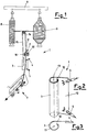
- Figure 1 shows the device mounted on a unit of the spinning machine.
- Figure 2 is a perspective view of the device.
- Figure 3 is a plan view of the device.
- Figures 4A-4E are schematic illustrations showing the device during the various stages of operation.
- the roving joining device 1 comprises a gripper device 2, a guide element 3, a first nozzle 4 and a second nozzle 5.
- the device 1 is housed on each unit (or position) of the spinning machine between the creel 6 and the drafting unit 7, which are conventional. Consequently the spinning machine comprises a number of devices equal to the number of units.
- the creel 6 is able to contain at least one depleting bobbin 8 and at least one full bobbin 9.
- the gripper device 2 comprises a movable abutment 10 and a fixed abutment 16 separated by a gap 11 between which the roving to be broken can slide.
- the guide element 3 is of tubular form with its axis 13 parallel to the axis of movement of the roving in operation.
- the element 3 is of open cross-section because of the presence of a longitudinal slit 12 through which the roving or rovings can be inserted.
- the cross-section of the element 3 is such that an air jet directed towards its interior is able to form a swirl essentially about and along the axis 13.
- the guide 3 can have any of the following shapes: a portion of a circle, a portion of an ellipse, a portion of a circumferential involute, a portion of an Archimedes spiral, or similar and/or intermediate shapes.
- the first nozzle 4 is connected to a compressed air generator (not shown) and is positioned at a first end of the tubular guide element 3 and orientated towards the interior of said guide element 3 so as to generate an air swirl extending along the entire extension of the element 3, and having a component in the direction of advancement of the roving in operation.
- the second nozzle 5 is also connected to a compressed air generator, preferably that to which the first nozzle 4 is connected, and is positioned at a second end of the tubular guide element 3 and orientated towards the interior of said guide element 3 to generate an air swirl rotating about the axis 13 and extending along the entire extension of the element 3, but with a component directed in the opposite direction to the direction of advancement of the roving in operation.
- This breakage of the old roving 14 determines the formation of the relative tail end 14A.
- the jet generated by the first nozzle 4 is interrupted.
- the jet generated by the second nozzle 5 generates a swirl causing the tail end 14A of the old roving 14 to wind for a number of helical turns onto the new roving 15 which at that moment is moving substantially taut within said guide element 3 ( Figure 4E).
- the tail end 14A is hence secured by friction to the new roving 15 and is wound thereon, to be hence drafted together with the new roving 15.
- the device of the invention joins the rovings together by a method comprising the following steps:
- the tail end of the old roving is also wound about the (new) roving in operation, which is taut along a rectilinear axis.
- the winding is achieved by a further air swirl rotating about the rovings and having a component in the opposite direction to the direction of advancement of the rovings in operation so as to form further helical turns.
- the tail end of the old roving can be formed either by programmed breakage of the roving or by natural depletion of the bobbin.
- the first case is however preferred because it reduces to a minimum a region which is critical as it can easily become a source of imperfection in the yarn being produced.
Landscapes
- Engineering & Computer Science (AREA)
- Mechanical Engineering (AREA)
- Textile Engineering (AREA)
- Spinning Or Twisting Of Yarns (AREA)
- Spinning Methods And Devices For Manufacturing Artificial Fibers (AREA)
- Treatment Of Fiber Materials (AREA)
- Preliminary Treatment Of Fibers (AREA)
Applications Claiming Priority (2)
| Application Number | Priority Date | Filing Date | Title |
|---|---|---|---|
| ITMI942192A IT1271046B (it) | 1994-10-26 | 1994-10-26 | Metodo e dispositivo per la giunzione degli stoppini applicabile a macchine per la filatura |
| ITMI942192 | 1994-10-26 |
Publications (2)
| Publication Number | Publication Date |
|---|---|
| EP0709502A1 true EP0709502A1 (de) | 1996-05-01 |
| EP0709502B1 EP0709502B1 (de) | 1998-07-08 |
Family
ID=11369776
Family Applications (1)
| Application Number | Title | Priority Date | Filing Date |
|---|---|---|---|
| EP95202742A Expired - Lifetime EP0709502B1 (de) | 1994-10-26 | 1995-10-11 | Verfahren und Vorrichtung zum Verbinden von Vorgarn in Spinnmaschinen |
Country Status (5)
| Country | Link |
|---|---|
| EP (1) | EP0709502B1 (de) |
| JP (1) | JPH0931776A (de) |
| DE (1) | DE69503334T2 (de) |
| ES (1) | ES2117827T3 (de) |
| IT (1) | IT1271046B (de) |
Families Citing this family (1)
| Publication number | Priority date | Publication date | Assignee | Title |
|---|---|---|---|---|
| KR101779277B1 (ko) | 2013-03-18 | 2017-09-18 | 봅스트 맥스 에스에이 | 이송 동안 플랫 물체를 배출하기 위한 디바이스 |
Citations (4)
| Publication number | Priority date | Publication date | Assignee | Title |
|---|---|---|---|---|
| JPS5516981A (en) * | 1979-02-09 | 1980-02-06 | Murata Mach Ltd | Pneumatic ending |
| DE3114538A1 (de) * | 1981-04-10 | 1983-01-13 | W. Schlafhorst & Co, 4050 Mönchengladbach | Verfahren und vorrichtung zum knotenfreien verbinden zweier faeden |
| DE3612229A1 (de) * | 1985-04-12 | 1986-12-04 | Murata Kikai K.K., Kyoto | Fadenspleissduese |
| DE3939881A1 (de) * | 1989-12-01 | 1991-06-06 | Rieter Ag Maschf | Verfahren und vorrichtung zum verbinden von faserbaendern, faserlunten, vorgarnen und garnen |
-
1994
- 1994-10-26 IT ITMI942192A patent/IT1271046B/it active IP Right Grant
-
1995
- 1995-10-11 DE DE69503334T patent/DE69503334T2/de not_active Expired - Fee Related
- 1995-10-11 EP EP95202742A patent/EP0709502B1/de not_active Expired - Lifetime
- 1995-10-11 ES ES95202742T patent/ES2117827T3/es not_active Expired - Lifetime
- 1995-10-24 JP JP7275942A patent/JPH0931776A/ja active Pending
Patent Citations (4)
| Publication number | Priority date | Publication date | Assignee | Title |
|---|---|---|---|---|
| JPS5516981A (en) * | 1979-02-09 | 1980-02-06 | Murata Mach Ltd | Pneumatic ending |
| DE3114538A1 (de) * | 1981-04-10 | 1983-01-13 | W. Schlafhorst & Co, 4050 Mönchengladbach | Verfahren und vorrichtung zum knotenfreien verbinden zweier faeden |
| DE3612229A1 (de) * | 1985-04-12 | 1986-12-04 | Murata Kikai K.K., Kyoto | Fadenspleissduese |
| DE3939881A1 (de) * | 1989-12-01 | 1991-06-06 | Rieter Ag Maschf | Verfahren und vorrichtung zum verbinden von faserbaendern, faserlunten, vorgarnen und garnen |
Non-Patent Citations (1)
| Title |
|---|
| PATENT ABSTRACTS OF JAPAN vol. 4, no. 42 (C - 005) 3 April 1980 (1980-04-03) * |
Also Published As
| Publication number | Publication date |
|---|---|
| ES2117827T3 (es) | 1998-08-16 |
| DE69503334D1 (de) | 1998-08-13 |
| EP0709502B1 (de) | 1998-07-08 |
| ITMI942192A0 (it) | 1994-10-26 |
| DE69503334T2 (de) | 1998-12-17 |
| JPH0931776A (ja) | 1997-02-04 |
| ITMI942192A1 (it) | 1996-04-26 |
| IT1271046B (it) | 1997-05-26 |
Similar Documents
| Publication | Publication Date | Title |
|---|---|---|
| US7594382B2 (en) | Joining method on a jet spinning machine, spinning device and jet spinning machine | |
| US4893461A (en) | Process and device for piecing with a spinning device operating with a pneumatic twisting unit | |
| EP3652368B1 (de) | Verfahren zum betreiben einer luftspinnvorrichtung | |
| DE2533655C2 (de) | Spinnmaschine zur Herstellung von gebündeltem Garn | |
| US4545193A (en) | Method for piecing fasciated yarn | |
| CN106414289A (zh) | 用于操作纺织机的方法和用于生产粗纱的纺织机 | |
| EP0787843A1 (de) | Anspinnverfahren für eine Spinnmaschine | |
| US20020139102A1 (en) | Core yarn, and method and device for manufacturing the same | |
| CN111527247A (zh) | 环锭纺纱机的气圈控制环 | |
| CN106414290B (zh) | 一种纺织机和用于操作这种纺织机的方法 | |
| KR100260219B1 (ko) | 방적방법 및 방적장치 | |
| US4619109A (en) | Method and apparatus for yarn piecing in a fasciated yarn spinning unit | |
| US4446687A (en) | Pneumatic yarn splicing apparatus for splicing core spun yarns | |
| CN100554542C (zh) | 用于使中断的纺纱过程恢复生产的方法和装置 | |
| EP3025996A1 (de) | Garnverbindungsvorrichtung, garnwickelmaschine und garnverbindungsverfahren | |
| EP0709502B1 (de) | Verfahren und Vorrichtung zum Verbinden von Vorgarn in Spinnmaschinen | |
| US4738093A (en) | Automotive splicer for splicing ends of spun yarn and a method of splicing spun yarns | |
| US4246749A (en) | Method of and apparatus for piecing yarn in open end rotor spinning units | |
| US4845935A (en) | Method and apparatus for threading roving into a running set of drafting rolls | |
| US5564473A (en) | Apparatus and method for correcting irregularities in a series shed weaving machine | |
| GB2156391A (en) | Open-end friction spinner piecing-up | |
| JPH06510095A (ja) | 新規に紡糸すべき糸を既存の糸端に自動継ぎするための方法及び装置 | |
| CN114207202B (zh) | 喷气纺纱机喷丝头的接纱方法及喷气纺纱机 | |
| JP2002363831A (ja) | コアヤーン及びその製造方法 | |
| DE2404387C3 (de) | Verfahren zum Aufwickeln von Garn auf eine leere Spule (Hülse) in einer Garnverarbeitungsmaschine und Spule (Hülse) zum Durchführen des Verfahrens |
Legal Events
| Date | Code | Title | Description |
|---|---|---|---|
| PUAI | Public reference made under article 153(3) epc to a published international application that has entered the european phase |
Free format text: ORIGINAL CODE: 0009012 |
|
| AK | Designated contracting states |
Kind code of ref document: A1 Designated state(s): CH DE ES FR LI |
|
| 17P | Request for examination filed |
Effective date: 19960730 |
|
| 17Q | First examination report despatched |
Effective date: 19960909 |
|
| GRAG | Despatch of communication of intention to grant |
Free format text: ORIGINAL CODE: EPIDOS AGRA |
|
| GRAG | Despatch of communication of intention to grant |
Free format text: ORIGINAL CODE: EPIDOS AGRA |
|
| GRAH | Despatch of communication of intention to grant a patent |
Free format text: ORIGINAL CODE: EPIDOS IGRA |
|
| GRAH | Despatch of communication of intention to grant a patent |
Free format text: ORIGINAL CODE: EPIDOS IGRA |
|
| GRAA | (expected) grant |
Free format text: ORIGINAL CODE: 0009210 |
|
| AK | Designated contracting states |
Kind code of ref document: B1 Designated state(s): CH DE ES FR LI |
|
| REG | Reference to a national code |
Ref country code: CH Ref legal event code: EP |
|
| REF | Corresponds to: |
Ref document number: 69503334 Country of ref document: DE Date of ref document: 19980813 |
|
| REG | Reference to a national code |
Ref country code: CH Ref legal event code: NV Representative=s name: AMMANN PATENTANWAELTE AG BERN |
|
| REG | Reference to a national code |
Ref country code: ES Ref legal event code: FG2A Ref document number: 2117827 Country of ref document: ES Kind code of ref document: T3 |
|
| ET | Fr: translation filed | ||
| PLBE | No opposition filed within time limit |
Free format text: ORIGINAL CODE: 0009261 |
|
| STAA | Information on the status of an ep patent application or granted ep patent |
Free format text: STATUS: NO OPPOSITION FILED WITHIN TIME LIMIT |
|
| 26N | No opposition filed | ||
| PGFP | Annual fee paid to national office [announced via postgrant information from national office to epo] |
Ref country code: DE Payment date: 20001002 Year of fee payment: 6 |
|
| PGFP | Annual fee paid to national office [announced via postgrant information from national office to epo] |
Ref country code: FR Payment date: 20001010 Year of fee payment: 6 |
|
| PGFP | Annual fee paid to national office [announced via postgrant information from national office to epo] |
Ref country code: CH Payment date: 20001011 Year of fee payment: 6 |
|
| PGFP | Annual fee paid to national office [announced via postgrant information from national office to epo] |
Ref country code: ES Payment date: 20001025 Year of fee payment: 6 |
|
| PG25 | Lapsed in a contracting state [announced via postgrant information from national office to epo] |
Ref country code: ES Free format text: LAPSE BECAUSE OF NON-PAYMENT OF DUE FEES Effective date: 20011012 |
|
| PG25 | Lapsed in a contracting state [announced via postgrant information from national office to epo] |
Ref country code: LI Free format text: LAPSE BECAUSE OF NON-PAYMENT OF DUE FEES Effective date: 20011031 Ref country code: CH Free format text: LAPSE BECAUSE OF NON-PAYMENT OF DUE FEES Effective date: 20011031 |
|
| REG | Reference to a national code |
Ref country code: CH Ref legal event code: PL |
|
| PG25 | Lapsed in a contracting state [announced via postgrant information from national office to epo] |
Ref country code: FR Free format text: LAPSE BECAUSE OF NON-PAYMENT OF DUE FEES Effective date: 20020628 |
|
| PG25 | Lapsed in a contracting state [announced via postgrant information from national office to epo] |
Ref country code: DE Free format text: LAPSE BECAUSE OF NON-PAYMENT OF DUE FEES Effective date: 20020702 |
|
| REG | Reference to a national code |
Ref country code: FR Ref legal event code: ST |
|
| REG | Reference to a national code |
Ref country code: ES Ref legal event code: FD2A Effective date: 20021113 |