EP0709650A2 - Behälterprüfverfahren und -vorrichtung zum Feststellen der Wanddicke von nicht runden Behältern - Google Patents
Behälterprüfverfahren und -vorrichtung zum Feststellen der Wanddicke von nicht runden Behältern Download PDFInfo
- Publication number
- EP0709650A2 EP0709650A2 EP95115562A EP95115562A EP0709650A2 EP 0709650 A2 EP0709650 A2 EP 0709650A2 EP 95115562 A EP95115562 A EP 95115562A EP 95115562 A EP95115562 A EP 95115562A EP 0709650 A2 EP0709650 A2 EP 0709650A2
- Authority
- EP
- European Patent Office
- Prior art keywords
- sensor
- containers
- container
- sensors
- sensor means
- Prior art date
- Legal status (The legal status is an assumption and is not a legal conclusion. Google has not performed a legal analysis and makes no representation as to the accuracy of the status listed.)
- Granted
Links
- 238000007689 inspection Methods 0.000 title claims abstract description 45
- 238000000034 method Methods 0.000 title claims abstract description 23
- 238000005259 measurement Methods 0.000 claims description 4
- 230000000694 effects Effects 0.000 claims description 3
- 239000011521 glass Substances 0.000 description 5
- 230000007246 mechanism Effects 0.000 description 5
- 238000005070 sampling Methods 0.000 description 4
- 239000003989 dielectric material Substances 0.000 description 2
- 239000000463 material Substances 0.000 description 2
- 238000011144 upstream manufacturing Methods 0.000 description 2
- 208000027418 Wounds and injury Diseases 0.000 description 1
- 238000010276 construction Methods 0.000 description 1
- 230000006378 damage Effects 0.000 description 1
- 230000007547 defect Effects 0.000 description 1
- 238000009658 destructive testing Methods 0.000 description 1
- 208000014674 injury Diseases 0.000 description 1
- 230000014759 maintenance of location Effects 0.000 description 1
- 238000004519 manufacturing process Methods 0.000 description 1
- 238000011326 mechanical measurement Methods 0.000 description 1
- 230000001681 protective effect Effects 0.000 description 1
- 230000000087 stabilizing effect Effects 0.000 description 1
Images


Classifications
-
- G—PHYSICS
- G01—MEASURING; TESTING
- G01B—MEASURING LENGTH, THICKNESS OR SIMILAR LINEAR DIMENSIONS; MEASURING ANGLES; MEASURING AREAS; MEASURING IRREGULARITIES OF SURFACES OR CONTOURS
- G01B7/00—Measuring arrangements characterised by the use of electric or magnetic techniques
- G01B7/02—Measuring arrangements characterised by the use of electric or magnetic techniques for measuring length, width or thickness
- G01B7/06—Measuring arrangements characterised by the use of electric or magnetic techniques for measuring length, width or thickness for measuring thickness
- G01B7/08—Measuring arrangements characterised by the use of electric or magnetic techniques for measuring length, width or thickness for measuring thickness using capacitive means
Definitions
- the present invention relates to apparatus for measuring the wall thickness of non-round containers and, more specifically, it includes apparatus and methods for measuring wall thickness of translating containers of various non-round configurations.
- the present invention has met the above-described need by providing apparatus and an associated method wherein capacitive sensors provide thickness information to oscillator means which are operatively associated therewith and generate corresponding voltage signals which are received by electronic processor means which determine wall thickness and effect comparison with desired thickness values.
- the sensors preferably have capacitive sensing element portions which are not in the same plane as other capacitive sensing elements or portions on the same sensor. It is preferred to provide sensor means on both sides of the path of travel over the container and to effect translational movement of the container through the inspection zone while resisting axial rotation of the container.
- the sensor means may include, as to each side of the path of container travel, a plurality of generally vertically spaced sensors.
- Each sensor in one embodiment, has a first surface and a second surface disposed at an angle thereto and abutting the first surface with discrete sensor elements disposed on the first surface, on the second surface and in the region of abutment of the first and second surfaces.
- the containers be subjected to translational movement between a first set of sensors on one side of the path of travel of the containers and a second set of sensors on the other side of the path of travel.
- the sensors may be movable so as to inspect different portions of the container.
- Figure 1 is a perspective view of a form of inspection apparatus of the present invention.
- Figure 2 is a partially schematic elevational view showing a portion of the inspection system of the present invention and an associated container which is being inspected.
- Figure 3 is a cross-sectional illustration through 3-3 of Figure 1 showing a portion of the container retention and drive means.
- Figure 4 is a schematic illustration showing a signal processing means of the present invention.
- Figure 5 is a partially schematic top plan view of a form of inspection system of the present invention adapted to inspect rectangular containers.
- Figure 6 is a perspective view of a form of sensor of the present invention suitable for inspecting rectangular containers.
- Figures 7 through 9 are schematic plan views showing the sensor of Figure 6 in three different positions in inspecting a rectangular container.
- Figure 10 is a top plan view of a portion of sensor means and associated apparatus employed to inspect rectangular containers.
- Figure 11 is a right elevational view of the apparatus of Figure 10.
- Figure 12 is a front elevational view of the apparatus of Figure 10.
- Figure 13 is an elevational view showing a modified form of sensor and the associated inspection apparatus of the present invention.
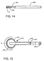
- Figures 14 and 15 are, respectively, a front elevational view and top plan view of a modified embodiment of a sensor of the present invention.
- Figures 16 through 18 are, respectively, schematic views showing the sensor of Figures 14 and 15 in different positions with respect to an oval container which is being inspected.
- non-round container will refer to containers of shapes which are not symmetrical with respect to the longitudinal axis of the container and shall expressly include, but not be limited to rectangular and oval shaped containers.
- FIG. 1 there is shown a pair of containers 2, 4 moving in the direction indicated by arrow A under the influence of conveyor 6.
- the containers which, in the form shown, are generally rectangular with curved corners, are moved in a translational manner through the inspection zone and are guided by a pair of first generally vertically spaced rails 10, 12 on one side of the path of travel of the containers 2, 4 and a corresponding pair of generally vertically spaced rails 14, 16 on the other side of the path of travel of containers 4, 2 with the spacings between rails 10 and 12, on the one hand, and rails 14 and 16 on the other, being such as to resist axial rotation of the containers 2, 4.
- FIG. 1 there is shown a housing 20 within which is an orbiting endless hold-down belt 24 which is engaged with pulleys 25, 26, 28 and has its undersurface 30 in intimate contact with the upper portion 32 of container neck 34.
- the belt 24 serves to resist undesired vertical movement of the container which could interfere with the accuracy of the thickness readings in respect of knowing precisely what vertical portion of the container 2 is being inspected.
- pulley 28 is driven by a suitable motor (not shown) to orbit the belt in the direction indicated by arrow B.
- Pulley 26 is an idler pulley and pulley 25 is a tensioner pulley which permits adjustment of the tension in endless belt 24.
- sensor means 40, 42, 44 are relatively vertically spaced from each other and are positioned on one side of the path of travel of the containers 2, 4.
- a second group of sensor means 50, 52, 54 are relatively vertically spaced from each other and are positioned on the opposite side of the path of travel of container 2.
- the sensors 40, 42, 44 and 50, 52, 54 are operatively associated with oscillator means 60, 62, 64, 70, 72, 74, respectively.
- the changes in capacitive sensors 40, 42, 44 and 50, 52, 54 are reflective of changes in wall thickness of container 2 and in the portion being inspected will be converted by the cooperating oscillators 60, 62, 64, 70, 72, 74, respectively, which receive the capacitive change signals through cables 80, 82, 84, 90, 92, 94, respectively, and convert the capacitive changes into corresponding voltage output signals which are delivered to associated multiplexers (not shown) through electrical leads 100, 102, 104, 110, 112, 114, respectively.
- the voltage signals are selectively passed through the multiplexer and through an analog-to- digital converter and into the electronic processor means for determination of a thickness value and comparison of the same with the desired thickness value in order to determine if a meaningful departure from the desired thickness has occurred.
- support column 115 is connected to horizontal support 117 to which rotatable shaft 116 is rotatably secured.
- the lower end of shaft 116 is fixedly secured to the sensor means assembly.
- Rotation of shaft 116, as by a pneumatic cylinder (not shown), for example, underlying cover plate 119 will cause the sensor means assembly to be rotated away from the conveyor 6 to facilitate machine setup, calibration or repair.
- a similar sensor means assembly support system would preferably be provided for the other assembly on the other side of conveyor 6.
- FIG. 4 there is shown schematically a group of four sensors 120, 124, 126, 128 which may be positioned on one side of the path of travel of the container in relatively vertically spaced relationship. Each cooperates with an associated oscillator 130, 134, 136, 138 with the output voltages of the oscillator being delivered to multiplexer 140 from which, on a selected basis, the voltages are introduced into analog-to-digital converter 142 which converts the voltages into digital pulses corresponding to the voltages which are emitted and delivered to electronic processor means 144 which, in the form shown, is a computer.
- the computer has entered therein a calibration factor indicating what material the container is made out of, such as, for example, glass or plastic and also the desired thickness or range of thicknesses of the container at the various elevations where it will be inspected.
- a calibration factor indicating what material the container is made out of, such as, for example, glass or plastic and also the desired thickness or range of thicknesses of the container at the various elevations where it will be inspected.
- This permits the digital pulses received from analog-to-digital converter 142 to be compared in the computer with the desired thickness reading to determine whether the thickness is within a tolerable range or if, in the alternative, the actual thickness has departed from the desired thickness by a sufficient amount as to make it desirable to reject the container. If so, the computer may emit a signal to a reject mechanism which will deliver the rejected container to an appropriate conveyor or bin so that it will not be mixed with acceptable containers.
- FIG. 5 there is shown a portion of the embodiment of Figures 1-3, a rectangular container 2 is transported by conveyor 6 in the direction indicated by arrow A.
- Guide rails 12, 16 serve to resist rotation of the container 2 as it is translated by conveyor means 6 through the inspection region.
- Sensors 40, 54 are mounted for rotational movement about pivots 160, 162, respectively, which are disposed within housings 164, 166 (FIG. 1). Pivots 160, 162 are preferably offset with respect to each other about 2.5 to 3.5 inches measured along the path of travel of the container 2. As a result, one leading corner will be inspected before the others.
- sensor 40 will be biased by spring means contained within housing 164 to urge it into a clockwise direction which urges it into intimate contact with container 2.
- Sensor 54 will be resiliently urged in a counter-clockwise direction so as to establish intimacy of contact with container 2.
- Any suitable means, such as coil springs 161, 163 disposed within housings 164, 166 may be employed to accomplish this resiliently maintained contact.
- the sensor 54 of Figure 6 has a pivot receiving opening 162, a spring receiving projection 164, a first arm 170, a second arm 176, and a flange portion 178.
- the area employed in sensing the glass thickness has been designated "S" and includes three discrete sensor elements 180, 182, 184.
- sensor element 180 is positioned on a first surface 188
- sensor 184 is positioned on a second surface 190, which is angularly disposed with respect to first surface 188
- sensor element 182 is positioned in the region where surfaces 188, 190 abut each other.
- the arm 176 extends across the leading upper corner 194 of container 2 with sensing element 180 in contact with corner 194 to inspect the wall thickness of the corner.
- sensor element 182 contacts side wall 196 of container 2 and progressively measures the wall thickness of the side wall 196 throughout its extent as the container moves thereby.
- the sensor element 184 is in contact with the trailing upper corner 198 of container 2 and inspects the wall thickness at that point.
- the mirror image sensor such as sensor 40 (FIG. 1), would similarly inspect the leading corner 200, side wall 202, and trailing corner 204 (FIG. 7) of the container, simultaneously, with the inspection performed by sensor 54.
- sensor 54 rotates about axis 162 under the influence of spring 163 (FIG. 5).
- the translated non-round container is subjected to inspection at a single elevation by the pair of sensors 40. 54.
- the container 2 in the embodiment shown in Figures 1 and 3 will also be inspected by other vertically spaced sensors positioned in the same location, such as 40, which is spaced from sensors 42 and 44, and sensor 54, which is vertically spaced from sensors 52 and 50. This will provide thickness readings of all corners and both sides at three distinct elevations.
- Figures 10 through 12 show the associated support and operating mechanism for the sensors, such as sensor 40.
- the sensor 40 pivots about 160 and is supported by arm 210 which has an adjustment mechanism 212, may move the sensor 40 along track 216 in a path generally perpendicular to the conveyor 6 in order to move the inspection station to the desired position.
- Locking handle 214 is then rotated to secure mechanism 212 in the desired position. This construction, therefore, moves the sensor means toward and away from the conveyor.
- torsion spring 215 urges the sensor into intimate contact with the container.
- Oscillator 60 is secured to the end of arm 210.
- a container 250 is transported by the inspection station on conveyor 253 with suitable hold-down belt means (not shown) and guide rails (not shown) which resist axial rotation of the container being employed.
- Sensors 252, 254, 256 are positioned on one side of the path of travel of the container 250 on conveyor 253 and are vertically spaced from each other and have their free ends in general alignment.
- Sensors 258, 260, 262 are disposed on the opposite side of the container path of travel and are relatively vertically spaced with respect to each other in general alignment and are adapted to inspect the container from the other side.
- Changes in capacitance of the sensors 252-262 will, respectively, be delivered to oscillators 272, 274, 276, 278, 280, 282 by means of cables 284, 286, 288, 290, 292, 294, respectively, with the signals being converted by the oscillators 272-282 (even numbers only) to corresponding voltages which are delivered to the multiplexer (not shown).
- a sensor which has an elongated arm which may be mounted to the supports through openings 261, 262 and, at the other end, contains an elongated curved sensing element 264.
- a protective tape element 265 is positioned over part of sensor 264 to minimize sensor wear.
- the sensing area S' is shown. It will be noted that in the preferred embodiment, the arcuate extent of this sensing element exceeds 180 degrees and, preferably, is greater than 220 degrees. It is also noted that unlike the embodiment shown in Figure 6, which has discrete sensing elements, the sensing element is preferably continuous.
- the sensor 258 of Figures 14 and 15 is shown inspecting an oval container 270. It will be noted the container is moving in a direction indicated by the arrow B. In the position shown in Figure 16, the right-hand portion of the sensor element 264 is inspecting a leading portion of the container 270. As the container continues to move, the sensor element slides along container surface and inspects the same. In Figure 17, the sensor 258 has the sensing element 264 in contact with intermediate container surface. As the container continues to progress, the trailing portion of the container is inspected and the sensor assumes the position shown in Figure 18. It will be appreciated that in effecting this inspection, the sensor element is moved through motion established by linkage arms 260, 292, 294 which are pivotally connected to sensor body 296.
- the linkage preferably includes link 260 which has sensor 264 disposed at one end.
- Link 260 is connected to link 292 at pivot 293 and to link 294 at pivot 297.
- Link 292 has right angled projection 300 and pivots about pivot 295 which may be a shoulder screw.
- Link 294 has elongated slot 299.
- a shoulder screw 301 which secures link 294 to the housing passes through slot 299 to limit travel of link 294.
- a mirror image sensor means to sensor means 258 will preferably be provided on the other side to inspect the other side surface of container 270, if desired. If such an arrangement is employed, it is preferred to stagger the two sensor means by offsetting one from the other by about 2 to 4 inches measured along the direction of container travel (arrow B).
- the oval container being inspected is moving in the direction of arrow B and has its major axis aligned with the direction of travel. In this position, the rear portion of continuous sensor 264 is in contact with the leading portion of container. It is preferred that torsion spring means disposed within the housing urge link 292 toward the position shown in Figure 16.
- the torsion spring means may be secured to the undersurface of housing 296, receive pivot pin 295 therethrough, and be secured to link 292.
- sensor 264 will continuously move along the container surface to have different portions of the sensor 264 progressively inspect different portions of the container 270.
- sensor 264 pivots about pivot point 297 until the free end of link 294 moves to the right and contacts projection 300, after which, the container 270 will cause movement of the entire sensor supporting linkage about pivot 295 against the force of the torsion spring. This causes the sensor to assume the position of Figure 17 and to progressively reach the position of Figure 18. After the container 270 moves beyond the position of Figure 18, the spring will return the sensor linkage to the position shown in Figure 16.
- the portions of the container 270 inspected in Figures 16 through 18, may be inspected at different elevations. Also, it is contemplated that a mirror image assembly of a sensor, such as 258, will be positioned on the opposite side of the path of travel of the container 270 to inspect the other surface walls (FIG. 18).
- a non-round container is transported through the inspection region.
- Means are provided to resist axial rotation thereof.
- Sensor means are preferably positioned on both sides of the path of travel of the container.
- the sensor means may have a single sensor or plurality of relatively vertically spaced sensors. In a preferred embodiment, on each sensor, either some individual sensor elements or a portion of a single sensor element will be in a different plane from other sensor elements on the same sensor or from portions of the same sensor element.
- Changes in capacitance are monitored and converted by oscillator means to a corresponding output voltage which by means of electronic processor means is converted into a wall thickness value which is compared with the desired wall thickness to determine whether an unacceptable departure in wall thickness exists.
- means which are known to those skilled in the art may be provided for automatic rejection of such containers.
- the method preferably employs sensors having one or more sensor elements with at least portions thereof not being disposed in the same plane as other portions or other elements thereof.
- Appropriate means are provided for moving the sensor means so as to correspond to the exterior configuration of the container.
- the senor has a plurality of individual sensor elements and in another preferred embodiment a continuous arcuate sensing element is provided.
- the invention is suitable for measuring wall thickness on dielectric containers, such as glass or plastic containers which may be bottles or jars, for example, and may be employed to measure thickness at various elevations of the container.
- dielectric containers such as glass or plastic containers which may be bottles or jars, for example, and may be employed to measure thickness at various elevations of the container.
- the present invention provides a means for rapidly inspecting wall thickness of non-round containers which are subjected to translational movement through the inspection station while resisting undesired axial rotation thereof.
- the sensor means are preferably movable to facilitate inspection of a number of container shapes.
- the movement of the containers through the inspection station is preferably continuous as there is no need to terminate motion during inspection.
- the sensor means are positioned on both sides of the path of travel of the container and have sensor elements so configurated as to efficiently measure wall thickness of the portion of the container being inspected at the elevation being inspected.
Landscapes
- Physics & Mathematics (AREA)
- General Physics & Mathematics (AREA)
- Measurement Of Length, Angles, Or The Like Using Electric Or Magnetic Means (AREA)
- Length Measuring Devices With Unspecified Measuring Means (AREA)
Applications Claiming Priority (2)
| Application Number | Priority Date | Filing Date | Title |
|---|---|---|---|
| US08/330,311 US5558233A (en) | 1994-10-27 | 1994-10-27 | Container inspection apparatus for determining the wall thickness of non-round containers and associated method |
| US330311 | 1994-10-27 |
Publications (3)
| Publication Number | Publication Date |
|---|---|
| EP0709650A2 true EP0709650A2 (de) | 1996-05-01 |
| EP0709650A3 EP0709650A3 (de) | 1996-11-27 |
| EP0709650B1 EP0709650B1 (de) | 2003-03-05 |
Family
ID=23289200
Family Applications (1)
| Application Number | Title | Priority Date | Filing Date |
|---|---|---|---|
| EP95115562A Expired - Lifetime EP0709650B1 (de) | 1994-10-27 | 1995-10-02 | Behälterprüfverfahren und -vorrichtung zum Feststellen der Wanddicke von nicht runden Behältern |
Country Status (4)
| Country | Link |
|---|---|
| US (2) | US5558233A (de) |
| EP (1) | EP0709650B1 (de) |
| DE (1) | DE69529794T2 (de) |
| ES (1) | ES2194037T3 (de) |
Families Citing this family (17)
| Publication number | Priority date | Publication date | Assignee | Title |
|---|---|---|---|---|
| US5532605A (en) * | 1994-10-27 | 1996-07-02 | Agr International, Inc. | Container inspection apparatus having diameter measuring means and associated method |
| US5675516A (en) * | 1995-09-27 | 1997-10-07 | Inex Vision Systems, Inc. | System and method for determining pushup of a molded glass container |
| US5923419A (en) * | 1997-06-16 | 1999-07-13 | Insight Control Systems International | System and method for optical inspection of recessed surfaces |
| US6061125A (en) * | 1998-01-27 | 2000-05-09 | Insight Control Systems International | Dual illumination apparatus for container inspection |
| US6620352B1 (en) | 2000-07-27 | 2003-09-16 | Ball Corporation | Automated material distribution control for stretch blow molded articles |
| US6962670B1 (en) | 2000-08-16 | 2005-11-08 | Eastman Chemical Company | Determination of layer thickness or non-uniformity of layer thickness based on fluorophore additives |
| DE50004988D1 (de) * | 2000-08-24 | 2004-02-12 | Plast Control Geraetebau Gmbh | Sensor zur kapazitiven Messung von Foliendicken |
| US6860025B1 (en) | 2002-12-30 | 2005-03-01 | Owens-Brockway Glass Container Inc. | Measurement of container wall thickness |
| DE20311436U1 (de) * | 2003-07-24 | 2003-09-18 | DBT Automation GmbH, 44534 Lünen | Vorrichtung zur Erfassung von Kratzerketten-Spannungszuständen |
| US7438192B1 (en) | 2004-05-28 | 2008-10-21 | Owens-Brockway Glass Container Inc. | Electronic control system for container indexing and inspection apparatus |
| US7385174B2 (en) * | 2006-06-26 | 2008-06-10 | Owens-Brockway Glass Container Inc. | Apparatus and method for measuring sidewall thickness of non-round transparent containers |
| DE102010054792A1 (de) * | 2010-12-16 | 2012-06-21 | Krones Aktiengesellschaft | Vorrichtung zum Behandeln von Behältnissen mit Behältnisausrichtung |
| JP5701800B2 (ja) * | 2012-03-16 | 2015-04-15 | 日本山村硝子株式会社 | センサー保持機構およびびんの肉厚検査装置 |
| US9341461B2 (en) | 2012-09-28 | 2016-05-17 | Nihon Yamamura Glass Co., Ltd. | Wall thickness inspection device |
| JP5802232B2 (ja) * | 2013-03-27 | 2015-10-28 | 日本山村硝子株式会社 | 容器の胴径不良検査装置 |
| JP6636464B2 (ja) * | 2015-01-21 | 2020-01-29 | 日本山村硝子株式会社 | 容器の肉厚検査装置 |
| WO2020150035A1 (en) | 2019-01-14 | 2020-07-23 | Agr International, Inc. | Method and apparatus for inspecting liquid filled hollow transparent articles |
Citations (8)
| Publication number | Priority date | Publication date | Assignee | Title |
|---|---|---|---|---|
| US2573824A (en) | 1946-10-17 | 1951-11-06 | Emhart Mfg Co | Machine for high-frequency determinations of wall thickness of bottles and the like |
| US4820972A (en) | 1987-07-02 | 1989-04-11 | Emhart Industries, Inc. | Wall thickness detector |
| US4862062A (en) | 1988-10-05 | 1989-08-29 | Emhart Industries, Inc. | Glass container inspection machine |
| US4870342A (en) | 1988-10-05 | 1989-09-26 | Emhart Industries, Inc. | Glass container wall thickness inspecting machine |
| US4930367A (en) | 1987-04-02 | 1990-06-05 | Koito Seisakusho Co., Ltd. | Perpendicularly intersecting gear device |
| US4965523A (en) | 1988-10-05 | 1990-10-23 | Emhart Industries, Inc. | Glass container inspection machine with rejection parameter selector |
| US4972566A (en) | 1988-10-05 | 1990-11-27 | Emhart Industries, Inc. | Method of repairing a glass container inspecting machine |
| US5097216A (en) | 1990-10-09 | 1992-03-17 | Agr International, Inc. | Apparatus for inspecting the wall thickness of a container and corresponding method |
Family Cites Families (11)
| Publication number | Priority date | Publication date | Assignee | Title |
|---|---|---|---|---|
| US2616068A (en) * | 1948-06-02 | 1952-10-28 | Emhart Mfg Co | Apparatus for gauging thickness |
| US3348313A (en) * | 1964-09-16 | 1967-10-24 | Urmenyi Laszlo | Device for detecting surface elevations in sheet material |
| US4077254A (en) * | 1977-04-25 | 1978-03-07 | Owens-Illinois, Inc. | Impact simulation apparatus |
| US4124112A (en) * | 1977-05-23 | 1978-11-07 | Owens-Illinois, Inc. | Odd-shaped container indexing starwheel |
| US4422035A (en) * | 1981-12-11 | 1983-12-20 | Extrude Hone Corporation | Capacitance measurement probe |
| EP0363115B1 (de) * | 1988-10-05 | 1992-12-23 | Emhart Glass Machinery Investments Inc. | Apparat zum Prüfen der Wanddicke von Glasbehältern |
| EP0363114B1 (de) * | 1988-10-05 | 1992-12-02 | Emhart Glass Machinery Investments Inc. | Glasbehälter-Prüfapparat |
| US4930364A (en) * | 1988-10-05 | 1990-06-05 | Emhart Industries, Inc. | Glass container inspecting machine |
| US4996658A (en) * | 1989-08-31 | 1991-02-26 | Emhart Industries, Inc. | Self-calibrating glass container inspection machine |
| US5121068A (en) * | 1989-12-26 | 1992-06-09 | Emhart Industries, Inc. | Sensor for sensing the wall thickness of an object |
| US5532605A (en) * | 1994-10-27 | 1996-07-02 | Agr International, Inc. | Container inspection apparatus having diameter measuring means and associated method |
-
1994
- 1994-10-27 US US08/330,311 patent/US5558233A/en not_active Expired - Fee Related
-
1995
- 1995-10-02 DE DE69529794T patent/DE69529794T2/de not_active Expired - Fee Related
- 1995-10-02 EP EP95115562A patent/EP0709650B1/de not_active Expired - Lifetime
- 1995-10-02 ES ES95115562T patent/ES2194037T3/es not_active Expired - Lifetime
- 1995-12-18 US US08/574,216 patent/US5917328A/en not_active Expired - Fee Related
Patent Citations (8)
| Publication number | Priority date | Publication date | Assignee | Title |
|---|---|---|---|---|
| US2573824A (en) | 1946-10-17 | 1951-11-06 | Emhart Mfg Co | Machine for high-frequency determinations of wall thickness of bottles and the like |
| US4930367A (en) | 1987-04-02 | 1990-06-05 | Koito Seisakusho Co., Ltd. | Perpendicularly intersecting gear device |
| US4820972A (en) | 1987-07-02 | 1989-04-11 | Emhart Industries, Inc. | Wall thickness detector |
| US4862062A (en) | 1988-10-05 | 1989-08-29 | Emhart Industries, Inc. | Glass container inspection machine |
| US4870342A (en) | 1988-10-05 | 1989-09-26 | Emhart Industries, Inc. | Glass container wall thickness inspecting machine |
| US4965523A (en) | 1988-10-05 | 1990-10-23 | Emhart Industries, Inc. | Glass container inspection machine with rejection parameter selector |
| US4972566A (en) | 1988-10-05 | 1990-11-27 | Emhart Industries, Inc. | Method of repairing a glass container inspecting machine |
| US5097216A (en) | 1990-10-09 | 1992-03-17 | Agr International, Inc. | Apparatus for inspecting the wall thickness of a container and corresponding method |
Also Published As
| Publication number | Publication date |
|---|---|
| DE69529794D1 (de) | 2003-04-10 |
| US5558233A (en) | 1996-09-24 |
| US5917328A (en) | 1999-06-29 |
| EP0709650A3 (de) | 1996-11-27 |
| DE69529794T2 (de) | 2003-10-02 |
| EP0709650B1 (de) | 2003-03-05 |
| ES2194037T3 (es) | 2003-11-16 |
Similar Documents
| Publication | Publication Date | Title |
|---|---|---|
| US5558233A (en) | Container inspection apparatus for determining the wall thickness of non-round containers and associated method | |
| US4096939A (en) | Apparatus for feeding glass containers at spaced intervals | |
| AU619894B2 (en) | Method and apparatus for tire inspection | |
| JPH04502214A (ja) | 干渉計を含む走査センサーシステム | |
| US5532605A (en) | Container inspection apparatus having diameter measuring means and associated method | |
| US4630276A (en) | Compact laser scanning system | |
| US3910124A (en) | Non-destructive testing procedures | |
| US6275032B1 (en) | Surface flatness measuring apparatus | |
| KR101158134B1 (ko) | 용기 경사를 광학 검사하는 장치 | |
| KR970000024B1 (ko) | 기계부품의 치수를 동적으로 검사하는 방법 및 장치 | |
| US4530243A (en) | Method for determining the position of a measuring sensor or a probe | |
| JPH06300689A (ja) | 透過法による青果物の内部品質測定法 | |
| JPS56168107A (en) | Surface inspecting device | |
| JP2909284B2 (ja) | 非破壊検査装置の容器位置決め装置 | |
| JP2503091Y2 (ja) | 円形物体の形状検査装置 | |
| JP2694966B2 (ja) | 青果物の内部品質検出機構 | |
| JPH05273119A (ja) | 拡散反射光とり出し方法及び拡散反射分光計測方法 | |
| RU2029290C1 (ru) | Фотоколориметрический газоанализатор | |
| US4698512A (en) | Length measuring apparatus | |
| JP3106981B2 (ja) | 外観検査装置 | |
| GB2084721A (en) | Automatic measurement of area of dimension | |
| JPH06300708A (ja) | フィルム欠損部検査装置 | |
| JPH04331365A (ja) | 樹脂成形品の非破壊検査方法 | |
| JPH0599841A (ja) | オンライン測光測定装置 | |
| JPH0458151A (ja) | 回転型探触子 |
Legal Events
| Date | Code | Title | Description |
|---|---|---|---|
| PUAI | Public reference made under article 153(3) epc to a published international application that has entered the european phase |
Free format text: ORIGINAL CODE: 0009012 |
|
| AK | Designated contracting states |
Kind code of ref document: A2 Designated state(s): CH DE ES FR GB IT LI |
|
| PUAL | Search report despatched |
Free format text: ORIGINAL CODE: 0009013 |
|
| AK | Designated contracting states |
Kind code of ref document: A3 Designated state(s): CH DE ES FR GB IT LI |
|
| 17P | Request for examination filed |
Effective date: 19970424 |
|
| 17Q | First examination report despatched |
Effective date: 19990629 |
|
| GRAG | Despatch of communication of intention to grant |
Free format text: ORIGINAL CODE: EPIDOS AGRA |
|
| GRAG | Despatch of communication of intention to grant |
Free format text: ORIGINAL CODE: EPIDOS AGRA |
|
| GRAH | Despatch of communication of intention to grant a patent |
Free format text: ORIGINAL CODE: EPIDOS IGRA |
|
| GRAH | Despatch of communication of intention to grant a patent |
Free format text: ORIGINAL CODE: EPIDOS IGRA |
|
| GRAA | (expected) grant |
Free format text: ORIGINAL CODE: 0009210 |
|
| AK | Designated contracting states |
Designated state(s): CH DE ES FR GB IT LI |
|
| REG | Reference to a national code |
Ref country code: GB Ref legal event code: FG4D |
|
| REG | Reference to a national code |
Ref country code: CH Ref legal event code: EP |
|
| REF | Corresponds to: |
Ref document number: 69529794 Country of ref document: DE Date of ref document: 20030410 Kind code of ref document: P |
|
| REG | Reference to a national code |
Ref country code: CH Ref legal event code: NV Representative=s name: PATENTANWAELTE SCHAAD, BALASS, MENZL & PARTNER AG |
|
| ET | Fr: translation filed | ||
| REG | Reference to a national code |
Ref country code: ES Ref legal event code: FG2A Ref document number: 2194037 Country of ref document: ES Kind code of ref document: T3 |
|
| PLBE | No opposition filed within time limit |
Free format text: ORIGINAL CODE: 0009261 |
|
| STAA | Information on the status of an ep patent application or granted ep patent |
Free format text: STATUS: NO OPPOSITION FILED WITHIN TIME LIMIT |
|
| 26N | No opposition filed |
Effective date: 20031208 |
|
| PGFP | Annual fee paid to national office [announced via postgrant information from national office to epo] |
Ref country code: GB Payment date: 20050928 Year of fee payment: 11 |
|
| PGFP | Annual fee paid to national office [announced via postgrant information from national office to epo] |
Ref country code: DE Payment date: 20050929 Year of fee payment: 11 |
|
| PGFP | Annual fee paid to national office [announced via postgrant information from national office to epo] |
Ref country code: FR Payment date: 20051010 Year of fee payment: 11 |
|
| PGFP | Annual fee paid to national office [announced via postgrant information from national office to epo] |
Ref country code: CH Payment date: 20051014 Year of fee payment: 11 |
|
| PGFP | Annual fee paid to national office [announced via postgrant information from national office to epo] |
Ref country code: ES Payment date: 20051129 Year of fee payment: 11 |
|
| PG25 | Lapsed in a contracting state [announced via postgrant information from national office to epo] |
Ref country code: LI Free format text: LAPSE BECAUSE OF NON-PAYMENT OF DUE FEES Effective date: 20061031 Ref country code: CH Free format text: LAPSE BECAUSE OF NON-PAYMENT OF DUE FEES Effective date: 20061031 |
|
| PGFP | Annual fee paid to national office [announced via postgrant information from national office to epo] |
Ref country code: IT Payment date: 20061031 Year of fee payment: 12 |
|
| PG25 | Lapsed in a contracting state [announced via postgrant information from national office to epo] |
Ref country code: DE Free format text: LAPSE BECAUSE OF NON-PAYMENT OF DUE FEES Effective date: 20070501 |
|
| REG | Reference to a national code |
Ref country code: CH Ref legal event code: PL |
|
| GBPC | Gb: european patent ceased through non-payment of renewal fee |
Effective date: 20061002 |
|
| REG | Reference to a national code |
Ref country code: FR Ref legal event code: ST Effective date: 20070629 |
|
| PG25 | Lapsed in a contracting state [announced via postgrant information from national office to epo] |
Ref country code: GB Free format text: LAPSE BECAUSE OF NON-PAYMENT OF DUE FEES Effective date: 20061002 |
|
| REG | Reference to a national code |
Ref country code: ES Ref legal event code: FD2A Effective date: 20061003 |
|
| PG25 | Lapsed in a contracting state [announced via postgrant information from national office to epo] |
Ref country code: FR Free format text: LAPSE BECAUSE OF NON-PAYMENT OF DUE FEES Effective date: 20061031 Ref country code: ES Free format text: LAPSE BECAUSE OF NON-PAYMENT OF DUE FEES Effective date: 20061003 |
|
| PG25 | Lapsed in a contracting state [announced via postgrant information from national office to epo] |
Ref country code: IT Free format text: LAPSE BECAUSE OF NON-PAYMENT OF DUE FEES Effective date: 20071002 |