EP0709663B1 - Erfassung von Fehlzündungen durch Beschleunigungen in einem Zyklus - Google Patents
Erfassung von Fehlzündungen durch Beschleunigungen in einem Zyklus Download PDFInfo
- Publication number
- EP0709663B1 EP0709663B1 EP19940117152 EP94117152A EP0709663B1 EP 0709663 B1 EP0709663 B1 EP 0709663B1 EP 19940117152 EP19940117152 EP 19940117152 EP 94117152 A EP94117152 A EP 94117152A EP 0709663 B1 EP0709663 B1 EP 0709663B1
- Authority
- EP
- European Patent Office
- Prior art keywords
- engine crankshaft
- acceleration
- proximate
- measuring
- reading
- Prior art date
- Legal status (The legal status is an assumption and is not a legal conclusion. Google has not performed a legal analysis and makes no representation as to the accuracy of the status listed.)
- Expired - Lifetime
Links
- 230000001133 acceleration Effects 0.000 title claims description 78
- 238000001514 detection method Methods 0.000 title description 9
- 238000000034 method Methods 0.000 claims description 30
- 230000006835 compression Effects 0.000 claims description 9
- 238000007906 compression Methods 0.000 claims description 9
- 238000010606 normalization Methods 0.000 claims description 8
- 239000000446 fuel Substances 0.000 claims description 4
- 238000002485 combustion reaction Methods 0.000 description 31
- 230000000694 effects Effects 0.000 description 8
- 238000010304 firing Methods 0.000 description 7
- 230000001939 inductive effect Effects 0.000 description 4
- 238000012545 processing Methods 0.000 description 4
- 238000012935 Averaging Methods 0.000 description 3
- 230000008901 benefit Effects 0.000 description 3
- 238000005259 measurement Methods 0.000 description 3
- 239000003054 catalyst Substances 0.000 description 2
- 238000010586 diagram Methods 0.000 description 2
- 238000006073 displacement reaction Methods 0.000 description 2
- 230000001052 transient effect Effects 0.000 description 2
- 230000005355 Hall effect Effects 0.000 description 1
- 238000013459 approach Methods 0.000 description 1
- 230000009286 beneficial effect Effects 0.000 description 1
- 230000015556 catabolic process Effects 0.000 description 1
- 230000008859 change Effects 0.000 description 1
- 230000007812 deficiency Effects 0.000 description 1
- 238000006731 degradation reaction Methods 0.000 description 1
- 230000008030 elimination Effects 0.000 description 1
- 238000003379 elimination reaction Methods 0.000 description 1
- 238000005516 engineering process Methods 0.000 description 1
- 230000007246 mechanism Effects 0.000 description 1
- 238000012986 modification Methods 0.000 description 1
- 230000004048 modification Effects 0.000 description 1
- 230000003287 optical effect Effects 0.000 description 1
- 230000008569 process Effects 0.000 description 1
- 230000001360 synchronised effect Effects 0.000 description 1
Images

Classifications
-
- G—PHYSICS
- G01—MEASURING; TESTING
- G01M—TESTING STATIC OR DYNAMIC BALANCE OF MACHINES OR STRUCTURES; TESTING OF STRUCTURES OR APPARATUS, NOT OTHERWISE PROVIDED FOR
- G01M15/00—Testing of engines
- G01M15/04—Testing internal-combustion engines
- G01M15/11—Testing internal-combustion engines by detecting misfire
Definitions
- This invention is related to the field of misfire detection within an internal combustion engine, and more specifically to a method, and corresponding apparatus, for determining misfire during a combustion event in an engine by interpreting acceleration of the engine's crankshaft.
- Systems are employed in electronic engine controls for detecting a misfire of a combustion event. If a cylinder repeatedly misfires, fuel is typically shut off to that cylinder on the next engine cycle. This prevents the passage of a large amount of unburned fuel to an exhaust catalyst. This is done to prevent degradation of the catalyst's performance and useful life, and thereby minimize emissions.
- Some misfire detection schemes use a rotational speed sensor mounted on an engine's crankshaft for converting engine rotation into an electrical signal. Some of these schemes monitor average angular velocity and attempt to predict misfiring based on signature analysis of this average engine crankshaft velocity. Other schemes rely on measuring average engine crankshaft acceleration. Both of these schemes suffer from inaccuracy because they rely on multi-combustion cycle averaging. This is problematic because these schemes are inaccurate and unreliable during transient operating conditions and other conditions related to combustion instability including engine crankshaft variability from cylinder to cylinder firings.
- misfire component of the sensed signal varies considerably in magnitude and frequency over the full operating range of the engine. Since averaging schemes rely on predicting a change from a steady state condition they inherently loose accuracy under these transient operating conditions. Also, non-combustion related effects are substantial. These effects are typically attributable to variations in engine load torque, friction torque, and inertia torque.
- the improvements described in the preferred embodiment can be applied in any reciprocating class engine including for instance, a diesel engine, stratified charge engine, or a spark ignition engine.
- a spark ignition engine In the preferred embodiment the application to a spark ignition engine is detailed.
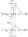
- the chart in FIG. 1 shows a signal 101 derived from a sensor that is measuring the angular acceleration of an engine crankshaft during a singular combustion cycle.
- the acceleration signal 101 shown is one resulting from a non-misfiring, or proper combustion cycle.
- the horizontal axis 103 is shown in terms of degrees of engine crankshaft angular rotation, relative to cylinder BDC compression 105, or bottom dead center, and cylinder TDC 107, or top dead center.
- the vertical axis 109 is expressed in terms of engine crankshaft acceleration. Notice that starting at cylinder BDC 105 the acceleration signal is substantially equal to zero. At this engine angular position a piston is in a compression portion of the cycle. As the engine crankshaft turns the engine crankshaft, thus the acceleration signal 101, decels, or has a negative acceleration. At 30° BTDC 113, or before top dead center, this negative acceleration trend reverses to a positive trend.
- the chart in FIG. 2 shows a signal indicative of a misfiring, or improper combustion cycle, and uses the same horizontal and vertical axes as FIG. 1.
- this signal When comparing this signal to that of FIG. 1 it can be seen that the engine crankshaft acceleration is substantially the same at 30° BTDC 201 and at cylinder TDC 203. However, at 30° ATDC 205 the absolute value of engine crankshaft acceleration is significantly lower than it was in FIG. 1 at 30° ATDC. It is this relationship, between engine crankshaft acceleration at 30° BTDC and 30° ATDC that is important to determining a misfire condition.
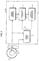
- FIG. 3 is a system block diagram of a misfire detection system that overcomes the disadvantages of the prior art.
- a method is described for implementing this system.
- a corresponding apparatus may be constructed to achieve the same advantages.
- a Motorola MC68HC11E9 microcontroller 300 executes the method embedded in firmware form.
- the firmware is represented later in flow chart form in FIG. 4.
- the use of the MC68HC11E9 microcontroller 300 is advantageous because it has integral counters that are useful in processing an acceleration signal described below. Those skilled in the art will recognize many other substantially equivalent hardware platforms for executing the method.
- a flywheel 301 is connected to an engine crankshaft and has lobes, or teeth 303 disposed on the exterior edge. In the preferred embodiment these are spaced at 10° intervals for the convenience of the method that is described. Of course, those skilled in the art will acknowledge that other tooth spacing will yield the same beneficial results.
- These teeth, 303 are sensed by an inductive transducer 305 as the flywheel 301 is driven by the engine crankshaft.
- the inductive transducer 305 provides a signal 313 indicative of the angular position, or velocity, of the flywheel 301.
- a separate singular tooth 307 is located at engine TDC and is sensed by another inductive transducer 309.
- the inductive transducer 309 provides a signal 311 indicative of TDC of the flywheel 301. Both of these signals 311 and 313 are provided to counter inputs of the MC68HC11E9 microcontroller 300 for further processing and are used to determine the individual cylinder TDC's necessary to execute the misfire detection method.
- Element 315 represents a firmware routine that determines, given the signal 313, and the signal 311, the absolute engine crankshaft position in terms of angular displacement.
- the flywheel teeth 303 are spaced at 10° intervals.
- This routine synchronized by the singular tooth 307 is located at flywheel TDC, simply counts teeth to determine the absolute engine crankshaft position in terms of angular displacement.
- a four stroke six cylinder engine is used. The firing order is 1, 4, 2, 5, 3, 6. Cylinder TDC is then 720°/6 or expected every 120°.
- cylinder 1 TDC is located at 0° flywheel position
- cylinder 4 TDC is located at 120° flywheel position
- cylinder 2 TDC is located at 240° flywheel position
- cylinder 5 TDC is located at 360° flywheel position
- cylinder 3 TDC is located at 480° flywheel position
- cylinder 6 TDC is located at 600° flywheel position.
- other engines with different firing orders and cylinder TDC's can be easily measured with other flywheel teeth arrangements and slight modifications to the routine 315.
- Those skilled in the art will recognize many other, equivalent means and methods to determine absolute engine crankshaft position.
- the angular position, or velocity, signal 313 is also provided to element 317 which determines the engine crankshaft acceleration.
- element 317 which determines the engine crankshaft acceleration.
- a counter embedded in the MC68HC11E9 microcontroller 300, counts the time between the flywheel teeth 303. The result is used to calculate the engine crankshaft acceleration by comparing successive values of measured times.
- a filter is then applied to remove a portion of the non-combustion torque related information. This may take the form of torsional vibrations, or very low frequency acceleration effects.
- the engine crankshaft acceleration 319 is provided to an element 321, along with a determined crankshaft angle 323 provided by element 315 as detailed earlier.
- Element 321 is the core of the method and is detailed in flow chart form in FIG. 4 later.
- a misfire indication is provided at an output 325 of element 321 .
- This misfire indication 325 is provided to an element 327 that, along with a determined crankshaft angle 323 provided by element 315, identifies the misfiring cylinder and shuts off the fuel to that particular cylinder at its next fueling cycle.
- the MC68HC11E9 microcontroller 300 has broader function as an engine controller with facilities to control fueling. These details are not provided because those skilled in the art are very familiar with numerous apparatus and methods for providing this function. Note that the method, and corresponding apparatus described herein may either conveniently be embedded into a larger system or used as a stand alone function.
- FIG. 4 is a method flow chart describing the operation of the misfire detection method. As mentioned above, this is representative of the firmware programmed into the MC68HC11E9 microcontroller 300. This firmware essentially recognizes the difference in behavior between the engine crankshaft acceleration signals shown in FIG. 1 and FIG. 2. Also, the routine also describes additional steps to eliminate any unfiltered non-combustion related engine crankshaft acceleration effects. This makes this method a very attractive alternative to prior art misfire detection systems because of the improved accuracy and reliability of misfire detection provided. This improved accuracy and reliability is partially due to the inherent, non-averaged nature of this approach and also to the unique, powerful concept of normalization of the measurement at cylinder TDC when no combustion related torque is possible.
- the engine crankshaft acceleration signal comprises torque related and non-combustion related information. In order to eliminate the torque related information it must be subtracted from both of the torque related measurements. This will be detailed below.
- step 401 the routine is entered every time a cylinder combustion cycle commences. Note that this routine shows that the method directly measures acceleration at a crankshaft angle of interest by waiting until it senses that angle. This is only one of the many ways to do this. Of course, those skilled in the art will recognize other, equivalent techniques such as capturing engine crankshaft acceleration's in separate routines and recalling and processing it here.
- step 403 the routine waits until the measured engine crankshaft angle is proximate a first predetermined engine crankshaft angle, in this case 30° before cylinder TDC. As noted earlier 30° before cylinder TDC is located within a compression stroke. When it is equal to 30° before cylinder TDC, in step 405, the routine fetches and stores the engine crankshaft acceleration reading as a variable named A30BTDC 407, which is indicative of the engine crankshaft acceleration at 30° before cylinder TDC.
- step 409 the routine waits until the measured engine crankshaft angle is proximate another predetermined engine crankshaft angle, in this case cylinder TDC, also referred to as a third predetermined engine crankshaft angle.
- step 411 the routine fetches and stores the engine crankshaft acceleration reading as a variable named ATDC 413, which is indicative of the engine crankshaft acceleration at cylinder TDC.
- This variable ATDC 413 is also known as the normalization coefficient. It is used to substantially eliminate effects due to non-combustion related behavior of the engine crankshaft acceleration 319.
- step 415 the routine waits until the measured engine crankshaft angle is proximate a second predetermined engine crankshaft angle, in this case 30° after cylinder TDC. As noted earlier 30° after cylinder TDC is located within an expansion stroke. When it is equal to 30° after cylinder TDC, in step 417, the routine fetches and stores the engine crankshaft acceleration as a variable named A30ATDC 419, which is indicative of the engine crankshaft acceleration at 30° after cylinder TDC.
- step 421 the three stored readings, or variables are recalled and combined, preferably by adding the A30BTDC 407 reading to the A30ATDC 419 reading and subtracting twice the ATDC 413 reading.
- This provides a NADC 423, or normalized acceleration coefficient.
- twice the variable ATDC 413 is subtracted because, as mentioned above, the non-combustion related acceleration must be subtracted from both the compression cycle reading and the expansion cycle reading.
- This same combustion cycle normalization, or elimination of non-combustion related effect offers a substantial accuracy advantage over the prior art. This is because accurate torque related acceleration is available for detecting a misfire condition, without pretending that historical, or averaged, non-combustion related effect can be subtracted from a real time reading, yielding a reliable result, as prior art systems did.
- step 425 the NADC variable 423 is compared to a predetermined limit. It is expected that during a normal combustion, or firing, event that the variable A30ATDC 419 is much greater than the variable A30BTDC 407. Because the signs of the acceleration readings are opposite, the combustion induced acceleration, for example shown in FIG. 1 at reference number 117, will result in a substantial positive result. However, if a misfire is in progress on a particular cylinder the readings will substantially cancel. When compared to the predetermined limit a normal firing will exceed the limit, and a misfire will not. If a misfire occurs a misfire indication is provided in step 427 and the routine repeats, starting at step 401. If a normal firing occurs the routine is repeated, starting at step 401.
- angles proximate 30° BTDC and proximate 30° ATDC are used to measure engine crankshaft acceleration during a compression and a succeeding expansion stroke
- other angular positions may be used as long as they are within a range of +-10° of the 30° positions. This is because for a typical slider crank mechanism used in current internal engines the peak combustion torque occurs in this range.
- a method for detecting a misfire condition by interpreting acceleration of an engine crankshaft within a singular combustion cycle that substantially overcomes the deficiencies of the prior art is described.
- a misfiring condition is detected.
- Multi-cycle averaging schemes with their inherent inaccuracy are avoided.
- measurement of another engine crankshaft acceleration, proximate cylinder TDC provides a normalization coefficient which, when combined with the other readings is used to substantially eliminate effects due to non-combustion related behavior of the engine crankshaft acceleration, thus providing a more accurate and reliable indication of a misfiring condition.
Landscapes
- Chemical & Material Sciences (AREA)
- Engineering & Computer Science (AREA)
- Combustion & Propulsion (AREA)
- Physics & Mathematics (AREA)
- General Physics & Mathematics (AREA)
- Combined Controls Of Internal Combustion Engines (AREA)
Claims (10)
- Verfahren zum Erfassen eines Fehlzündungszustands durch Interpretieren der Beschleunigung einer Motorkurbelwelle, die folgenden Schritte umfassend:Messen einer ersten Motorkurbelwellenbeschleunigung (405) nahe einem ersten vorgegebenen Motorkurbelwellenwinkel in einem Kompressionstakt und Schaffen eines ersten Meßwerts (407;, der eine Anzeige dieser ersten Motorkurbelwellenbeschleunigung ist;Messen einer zweiten Motorkurbelwellenbeschleunigung (417) nahe einem zweiten vorgegebenen Motorkurbelwellenwinkel, der sich in einem sich diesem Kompressionstakt anschließenden Expansionstakt befindet, und Schaffen eines zweiten Meßwerts (419), der eine Anzeige dieser zweiten Motorkurbelwellenbeschleunigung ist;Kombinieren (421) des ersten Meßwerts und des zweiten Meßwerts und Schaffer eines Beschleunigungskoeffizienten (423), der eine Anzeige dieser kombinierten Meßwerte ist; undSchaffen einer Fehlzündungsanzeige (427), wenn der Beschleunigungskoeffizient einen vorgegebenen Grenzwert nicht überschreitet.
- Verfahren nach Anspruch 1, bei dem dieser Schritt des Messens einer ersten Motorkurbelwellenbeschleunigung nahe an einem ersten vorgegebenen Motorkurbelwellenwinkel das Messen einer ersten Motorkurbelwellenbeschleunigung nahe bei 30° vor dem oberen Tospunkt eines Zylinders umfaßt.
- Verfahren nach Anspruch 1 oder Anspruch 2, bei dem dieser Schritt des Messens einer zweiten Motorkurbelwellenbeschleunigung nahe an einem zweiten vorgegebenen Motorkurbelwellenwinkel das Messer einer zweiten Motorkurbelwellenbeschleunigung nahe bei 30° nach dazu oberen Totpunkt des Zylinders umfaßt.
- Verfahren nach Anspruch 1, bei dem der Schritt des Messens einer ersten Motorkurbelwellenbeschleunigung nahe an einem ersten vorgegebenen Motorkurbelwellenwinkel das Messen einer ersten Motorkurbelwellenbeschleunigung in einem Bereich von ±10° um den Winkel 30° vor dem oberen Totpunkt eines Zylinders umfaßt und dieser Schritt des Messens einer zweiten Motorkurbelwellenbeschleunigung nahe an einem zweiten vorgegebenen Motorkurbelwellenwinkel das Messen einer zweiten Motorkurbelwellenbeschleuni. gung in einem Bereich von ±10° um den Winkel 30° nach dem oberen Totpunkt umfaßt.
- Verfahren nach Anspruch 1, bei dem der Schritt des Kombinierens das Addieren des ersten Meßwerts und des zweiten Meßwerts umfaßt.
- Verfahren nach Anspruch 1, weiter die folgenden Schritte umfassend:Messen einer dritten Motorkurbelwellenbeschleunigung nahe am Zylinder-TDC (oberer Totpunkt) und Schaffen eines Normierungskoeffizienten;Kombinieren des Normierungskoeffizienten mit dem Beschleunigungskoeffizienten und Schaffen eines normierten Beschleungigungskoeffizienten; undSchaffen der Fehlzündungsanzeige, wenn der normierte Beschleunigungskoeffizient einen vorgegebenen Grenzwert nicht überschreitet.
- Verfahren nach Anspruch 6, bei dem dieser Schritt des Kombinierens das Subtrahieren des Normierungskoeffizienten vom Beschleunigungskoeffizienten umfaßt.
- Verfahren nach Anspruch 6, bei dem dieser Schritt des Kombinierens das Subtrahieren des zweifachen Normierungskoeffizienten vom Beschleunigungskoeffizienten umfaßt.
- Vorrichtung zum Erfassen eines Fehlzündungszustands durch Interpretieren der Beschleunigung einer Motorkurbelwelle umfassend: Mittel zum Messen einer ersten Motorkurbelwellenbeschleunigung nahe an einem ersten vorgegebenen Motorkurbelwellenwinkel, der sich in einem Kompressionstakt befindet, und zum Schaffen eines ersten Meßwerts, der eine Anzeige dieser ersten Motorkurbelwellenbeschleunigung ist; Mittel zum Messen einer zweiten Motorkurbelwellenbeschleunigung nahe an einem zweiten vorgegebenen Motorkurbelwellenwinkel, der sich in einen diesem Kompressionstakt anschließenden Expansionstakt befindet, und zum Schaffen eines zweiten Meßwerts, der eine Anzeige dieser zweiten Motorkurbelwellenbeschleunigung ist; Mittel zum Kombinieren des ersten Meßwerts und des zweiten Meßwerts und zum Schaffen eines Beschleunigungskoeffizienten; und Mittel zum Schaffen einer Fehlzündungsanzeige, wenn der Beschleunigungskoeffizient einen vorgegebenen Grenzwert nicht überschreitet.
- Vorrichtung nach Anspruch 9, ferner auf diese Fehlzündungsanzeige reagierende Mittel zum Abschalten des Kraftstoffs umfassend.
Priority Applications (3)
| Application Number | Priority Date | Filing Date | Title |
|---|---|---|---|
| ES94117152T ES2149231T3 (es) | 1994-10-31 | 1994-10-31 | Deteccion de fallos del encendido mediante aceleraciones en un ciclo. |
| EP19940117152 EP0709663B1 (de) | 1994-10-31 | 1994-10-31 | Erfassung von Fehlzündungen durch Beschleunigungen in einem Zyklus |
| DE1994625375 DE69425375T2 (de) | 1994-10-31 | 1994-10-31 | Erfassung von Fehlzündungen durch Beschleunigungen in einem Zyklus |
Applications Claiming Priority (1)
| Application Number | Priority Date | Filing Date | Title |
|---|---|---|---|
| EP19940117152 EP0709663B1 (de) | 1994-10-31 | 1994-10-31 | Erfassung von Fehlzündungen durch Beschleunigungen in einem Zyklus |
Publications (2)
| Publication Number | Publication Date |
|---|---|
| EP0709663A1 EP0709663A1 (de) | 1996-05-01 |
| EP0709663B1 true EP0709663B1 (de) | 2000-07-26 |
Family
ID=8216424
Family Applications (1)
| Application Number | Title | Priority Date | Filing Date |
|---|---|---|---|
| EP19940117152 Expired - Lifetime EP0709663B1 (de) | 1994-10-31 | 1994-10-31 | Erfassung von Fehlzündungen durch Beschleunigungen in einem Zyklus |
Country Status (3)
| Country | Link |
|---|---|
| EP (1) | EP0709663B1 (de) |
| DE (1) | DE69425375T2 (de) |
| ES (1) | ES2149231T3 (de) |
Cited By (1)
| Publication number | Priority date | Publication date | Assignee | Title |
|---|---|---|---|---|
| US12234785B2 (en) | 2020-08-12 | 2025-02-25 | Caterpillar Energy Solutions Gmbh | Method and control unit for identifying misfire subjected cylinders of an internal combustion engine |
Families Citing this family (4)
| Publication number | Priority date | Publication date | Assignee | Title |
|---|---|---|---|---|
| US6199426B1 (en) | 1996-12-17 | 2001-03-13 | Toyota Jidosha Kabushiki Kaisha | Method of detection of output fluctuation in internal combustion engine |
| US6801848B1 (en) * | 2003-06-25 | 2004-10-05 | General Motors Corporation | Methods and apparatus for sensing misfire in an internal combustion engine |
| JP4490721B2 (ja) * | 2004-04-12 | 2010-06-30 | 三菱自動車工業株式会社 | エンジンの失火検出装置及びエンジンの燃焼制御装置 |
| JP7205334B2 (ja) * | 2019-03-22 | 2023-01-17 | トヨタ自動車株式会社 | 内燃機関の診断装置 |
Family Cites Families (3)
| Publication number | Priority date | Publication date | Assignee | Title |
|---|---|---|---|---|
| DE2507057A1 (de) * | 1975-02-19 | 1976-09-02 | Bosch Gmbh Robert | Verfahren und vorrichtung zur bestimmung der laufunruhe einer brennkraftmaschine |
| US5337240A (en) * | 1990-09-20 | 1994-08-09 | Mitsubishi Denki Kabushiki Kaisha | Misfiring sensing apparatus |
| DE69313814T2 (de) * | 1992-06-09 | 1998-04-09 | Mitsubishi Motors Corp | Verfahren zur erkennung von fehlzündungen durch drehzahländerung der kurbelwelle |
-
1994
- 1994-10-31 ES ES94117152T patent/ES2149231T3/es not_active Expired - Lifetime
- 1994-10-31 DE DE1994625375 patent/DE69425375T2/de not_active Expired - Fee Related
- 1994-10-31 EP EP19940117152 patent/EP0709663B1/de not_active Expired - Lifetime
Cited By (1)
| Publication number | Priority date | Publication date | Assignee | Title |
|---|---|---|---|---|
| US12234785B2 (en) | 2020-08-12 | 2025-02-25 | Caterpillar Energy Solutions Gmbh | Method and control unit for identifying misfire subjected cylinders of an internal combustion engine |
Also Published As
| Publication number | Publication date |
|---|---|
| DE69425375D1 (de) | 2000-08-31 |
| EP0709663A1 (de) | 1996-05-01 |
| ES2149231T3 (es) | 2000-11-01 |
| DE69425375T2 (de) | 2001-02-15 |
Similar Documents
| Publication | Publication Date | Title |
|---|---|---|
| US5915272A (en) | Method of detecting low compression pressure responsive to crankshaft acceleration measurement and apparatus therefor | |
| EP0437057B1 (de) | Methode und Gerät um den Verbrennungszustand in einer mehrzylindrigen Brennkraftmaschine zu detektieren | |
| AU750684B2 (en) | Process for detecting a misfire in an internal combustion engine and system for carrying out said process | |
| JPH04365958A (ja) | 内燃機関用失火検出装置 | |
| US6332352B1 (en) | Engine torque-detecting method and an apparatus therefor | |
| JP2666232B2 (ja) | 内燃エンジンの燃焼状態検出装置 | |
| JPH03202660A (ja) | エンジンの失火判定装置 | |
| JP3466207B2 (ja) | 動作行程識別方法および識別装置 | |
| JP2019190464A (ja) | 大型低速エンジンの燃焼分析装置及びこれを利用したエンジンの燃焼状態判断方法 | |
| US5638278A (en) | Apparatus for detecting an occurence of misfiring in an engine cylinder | |
| US5503007A (en) | Misfire detection method and apparatus therefor | |
| KR20180093883A (ko) | 기관 제어 방법 및 기관 제어 장치 | |
| JPH06129298A (ja) | 内燃機関の失火検出装置 | |
| JP2807737B2 (ja) | 内燃エンジンの燃焼状態検出装置 | |
| EP0709663B1 (de) | Erfassung von Fehlzündungen durch Beschleunigungen in einem Zyklus | |
| US5758307A (en) | Normalized misfire detection method | |
| US5562082A (en) | Engine cycle identification from engine speed | |
| JPH0436044A (ja) | エンジンの失火診断装置 | |
| JP2527798B2 (ja) | 内燃機関の燃焼状態検出装置 | |
| JP2559516B2 (ja) | 内燃機関の燃焼状態検出装置 | |
| JPH04113244A (ja) | 内燃機関の失火検出装置 | |
| JP2675921B2 (ja) | 内燃機関の失火検出装置 | |
| JPH08144837A (ja) | 失火検出装置 | |
| JPH08121236A (ja) | 不点火検出方法およびその装置 | |
| JPH086676B2 (ja) | 内燃機関の失火診断装置 |
Legal Events
| Date | Code | Title | Description |
|---|---|---|---|
| PUAI | Public reference made under article 153(3) epc to a published international application that has entered the european phase |
Free format text: ORIGINAL CODE: 0009012 |
|
| AK | Designated contracting states |
Kind code of ref document: A1 Designated state(s): DE ES FR GB IT |
|
| 17P | Request for examination filed |
Effective date: 19961104 |
|
| 17Q | First examination report despatched |
Effective date: 19970625 |
|
| GRAG | Despatch of communication of intention to grant |
Free format text: ORIGINAL CODE: EPIDOS AGRA |
|
| RTI1 | Title (correction) |
Free format text: MISFIRE DETECTION BY ACCELERATIONS IN ONE CYCLE |
|
| GRAG | Despatch of communication of intention to grant |
Free format text: ORIGINAL CODE: EPIDOS AGRA |
|
| GRAH | Despatch of communication of intention to grant a patent |
Free format text: ORIGINAL CODE: EPIDOS IGRA |
|
| GRAH | Despatch of communication of intention to grant a patent |
Free format text: ORIGINAL CODE: EPIDOS IGRA |
|
| GRAA | (expected) grant |
Free format text: ORIGINAL CODE: 0009210 |
|
| ITF | It: translation for a ep patent filed | ||
| AK | Designated contracting states |
Kind code of ref document: B1 Designated state(s): DE ES FR GB IT |
|
| REF | Corresponds to: |
Ref document number: 69425375 Country of ref document: DE Date of ref document: 20000831 |
|
| ET | Fr: translation filed | ||
| REG | Reference to a national code |
Ref country code: ES Ref legal event code: FG2A Ref document number: 2149231 Country of ref document: ES Kind code of ref document: T3 |
|
| PLBE | No opposition filed within time limit |
Free format text: ORIGINAL CODE: 0009261 |
|
| STAA | Information on the status of an ep patent application or granted ep patent |
Free format text: STATUS: NO OPPOSITION FILED WITHIN TIME LIMIT |
|
| 26N | No opposition filed | ||
| REG | Reference to a national code |
Ref country code: GB Ref legal event code: IF02 |
|
| PGFP | Annual fee paid to national office [announced via postgrant information from national office to epo] |
Ref country code: GB Payment date: 20020913 Year of fee payment: 9 |
|
| PGFP | Annual fee paid to national office [announced via postgrant information from national office to epo] |
Ref country code: FR Payment date: 20021003 Year of fee payment: 9 |
|
| PGFP | Annual fee paid to national office [announced via postgrant information from national office to epo] |
Ref country code: ES Payment date: 20021016 Year of fee payment: 9 |
|
| PGFP | Annual fee paid to national office [announced via postgrant information from national office to epo] |
Ref country code: DE Payment date: 20021031 Year of fee payment: 9 |
|
| PG25 | Lapsed in a contracting state [announced via postgrant information from national office to epo] |
Ref country code: GB Free format text: LAPSE BECAUSE OF NON-PAYMENT OF DUE FEES Effective date: 20031031 |
|
| PG25 | Lapsed in a contracting state [announced via postgrant information from national office to epo] |
Ref country code: ES Free format text: LAPSE BECAUSE OF NON-PAYMENT OF DUE FEES Effective date: 20031103 |
|
| PG25 | Lapsed in a contracting state [announced via postgrant information from national office to epo] |
Ref country code: DE Free format text: LAPSE BECAUSE OF NON-PAYMENT OF DUE FEES Effective date: 20040501 |
|
| GBPC | Gb: european patent ceased through non-payment of renewal fee |
Effective date: 20031031 |
|
| PG25 | Lapsed in a contracting state [announced via postgrant information from national office to epo] |
Ref country code: FR Free format text: LAPSE BECAUSE OF NON-PAYMENT OF DUE FEES Effective date: 20040630 |
|
| REG | Reference to a national code |
Ref country code: FR Ref legal event code: ST |
|
| REG | Reference to a national code |
Ref country code: ES Ref legal event code: FD2A Effective date: 20031103 |
|
| PG25 | Lapsed in a contracting state [announced via postgrant information from national office to epo] |
Ref country code: IT Free format text: LAPSE BECAUSE OF NON-PAYMENT OF DUE FEES;WARNING: LAPSES OF ITALIAN PATENTS WITH EFFECTIVE DATE BEFORE 2007 MAY HAVE OCCURRED AT ANY TIME BEFORE 2007. THE CORRECT EFFECTIVE DATE MAY BE DIFFERENT FROM THE ONE RECORDED. Effective date: 20051031 |