EP0709847A2 - Digitale Kodierung und Fehlerkorrektur - Google Patents
Digitale Kodierung und Fehlerkorrektur Download PDFInfo
- Publication number
- EP0709847A2 EP0709847A2 EP95307504A EP95307504A EP0709847A2 EP 0709847 A2 EP0709847 A2 EP 0709847A2 EP 95307504 A EP95307504 A EP 95307504A EP 95307504 A EP95307504 A EP 95307504A EP 0709847 A2 EP0709847 A2 EP 0709847A2
- Authority
- EP
- European Patent Office
- Prior art keywords
- signals
- error
- reproduced
- errors
- correcting
- Prior art date
- Legal status (The legal status is an assumption and is not a legal conclusion. Google has not performed a legal analysis and makes no representation as to the accuracy of the status listed.)
- Withdrawn
Links
Images




Classifications
-
- G—PHYSICS
- G11—INFORMATION STORAGE
- G11B—INFORMATION STORAGE BASED ON RELATIVE MOVEMENT BETWEEN RECORD CARRIER AND TRANSDUCER
- G11B20/00—Signal processing not specific to the method of recording or reproducing; Circuits therefor
- G11B20/10—Digital recording or reproducing
- G11B20/18—Error detection or correction; Testing, e.g. of drop-outs
- G11B20/1833—Error detection or correction; Testing, e.g. of drop-outs by adding special lists or symbols to the coded information
-
- G—PHYSICS
- G11—INFORMATION STORAGE
- G11B—INFORMATION STORAGE BASED ON RELATIVE MOVEMENT BETWEEN RECORD CARRIER AND TRANSDUCER
- G11B20/00—Signal processing not specific to the method of recording or reproducing; Circuits therefor
- G11B20/10—Digital recording or reproducing
- G11B20/18—Error detection or correction; Testing, e.g. of drop-outs
-
- H—ELECTRICITY
- H03—ELECTRONIC CIRCUITRY
- H03M—CODING; DECODING; CODE CONVERSION IN GENERAL
- H03M13/00—Coding, decoding or code conversion, for error detection or error correction; Coding theory basic assumptions; Coding bounds; Error probability evaluation methods; Channel models; Simulation or testing of codes
- H03M13/03—Error detection or forward error correction by redundancy in data representation, i.e. code words containing more digits than the source words
- H03M13/05—Error detection or forward error correction by redundancy in data representation, i.e. code words containing more digits than the source words using block codes, i.e. a predetermined number of check bits joined to a predetermined number of information bits
- H03M13/13—Linear codes
- H03M13/15—Cyclic codes, i.e. cyclic shifts of codewords produce other codewords, e.g. codes defined by a generator polynomial, Bose-Chaudhuri-Hocquenghem [BCH] codes
Definitions
- the present invention relates generally to digital coding and error correction and can be applied to a digital coding method and apparatus for correcting digitally encoded data which have been corrupted by burst errors.
- This invention is particularly suited for the reproduction of encoded data from data storage media but is also advantageously implemented in other channel coding systems.
- the reproduction of recorded digital data from a storage medium is commonly an imperfect process.
- a variety of different physical and environmental conditions can influence the recording and reproduction processes and change the characteristics of a storage medium itself to cause errors in the reproduced data.
- the surface of the disk may suffer from irregularities such as bubbles in the coating of the disk, scratches marring the disk surface, or the like, resulting from an imperfect manufacturing process or from mishandling of the disk.
- dust and condensation frequently interfere with the operation of recording and reproducing heads utilized in such systems, causing the system to lose synchronization (tracking) with the storage medium or otherwise malfunction, resulting in the misrecording or misreproduction of data.
- allocation strategies have been developed to enable a data storage system to physically avoid reading corrupted portions of a storage medium. For example, during the manufacturing of magneto-optical disks, those data sectors of a particular disk determined to be faulty are simply removed from the data map for the disk. Data intended for the faulty sectors are rerouted to alternate adjacent sectors of the disk so that data is not recorded on or reproduced from the faulty sectors and instead, the alternate sectors are utilized. If a sector becomes corrupted after ordinary use of the disk has commenced, the data storage system avoids the corrupt sector by rerouting data intended for or requested from that sector to an alternate sector established in a dedicated region of the disk.
- portions of data to be recorded are augmented with code data such that the augmented (coded) portions of data satisfy specific mathematical relationships.
- code data such that the augmented (coded) portions of data satisfy specific mathematical relationships.
- some errors introduced by the recording and reproducing processes can be detected by recognizing that the reproduced data does not satisfy the original mathematical relationships.
- the data reproduction process may be restarted in an attempt to correctly reproduce the data.
- the original recorded data can be reconstructed from the inaccurately reproduced data by altering the reproduced data so that it satisfies the original mathematical relationships.
- Cyclic redundancy check (CRC) codes and parity bits are often employed for these purposes. Besides reducing the storage capacity of the disk by recording code data along with the information data, such techniques are often overwhelmed by consecutive errors, resulting in the misdetection of errors and necessitating the repeated reproduction of inaccurately reproduced data.
- Errors in a stream of reproduced data can be roughly categorized as either random errors, which affect relatively short sequences of data and appear at "random" intervals, or burst errors, which affect much longer contiguous sequences of data. Due to the often considerable amount of contiguous data typically corrupted by a burst error, correction of such an error presents a difficult coding challenge.
- Reed-Solomon (RS) codes (Reed and Solomon, 1960) have proven to be a useful coding technique for detecting and correcting burst errors in satellite communications systems and magnetic and optical recording/reproducing systems.
- RS codes are symbol-oriented non-binary BCH (Bose, Chaudhuri and Hocquenghem) codes wherein the symbols may represent binary m-bit words. According to a simple application of this technique, given a data stream wherein each word contains k symbols, a codeword consisting of n symbols is produced by augmenting each word of information with n-k "check" symbols. The "distance" between two codewords is defined as the number of corresponding positions in the codewords in which the two codewords contain different symbols.
- the distance between codewords "vghb” and “cghc” is two because the first and fourth positions in the codewords differ.
- the "minimum distance” d for the code can be defined as the least “distance” between any two possible codewords.
- the three parameters n, k, and d are thus employed to distinguish among codes, e.g. (n, k, d) RS code.
- Error correcting ability of a code is governed by the equation d ⁇ 2t + 1 where d is the minimum distance and t is the number of erroneous symbols in each codeword that can be corrected. For example, if the minimum distance of a code equals 17, then no more than 8 symbols in each codeword can be corrected.
- Extension of the error detection and error correction capabilities of an already efficient RS code thus typically involves increasing the code's minimum distance d.
- the minimum distance d is increased by increasing the number of n-k check symbols added to each word of data and, consequently, reducing the amount of information that can be stored on the disk. Such an increase in d also increases the redundancy of the code.
- an error-correcting apparatus for detecting and correcting a burst error affecting a plurality of reproduced signals representing adjacent data words.
- the apparatus includes a grouping device for dividing the reproduced signals into groups of signals, each group containing a predetermined number of adjacent data words and sharing at least one data word with another group.
- the apparatus further includes a calculating device, responsive to the groups of signals, for reproducing a plurality of syndrome signals representing a plurality of syndromes calculated for each group of signals and a determining device for determining the position of an error, if any, in each group of signals as a function of the syndrome signals.
- a burst error detecting device detects a burst error in the reproduced signals as a function of the determined positions of a plurality of errors.
- Embodiments of the present invention provide a coding apparatus and method for detecting and correcting relatively long burst errors.
- Still further embodiments of the present invention provide a coding apparatus and method for determining the location and size of a burst error in a quantity of data.
- disk drive 20 is configured to service at least one type of disk media and preferably accommodates several different types, such as CD-ROMs, partial CD-ROMs, magneto-optical disks, write-once disks, optical disks incorporating phase-change media, and partial disks having a writable area (RAM) and a read-only area (ROM).
- Disk 22 may be permanently fixed within drive 20 or, preferably, removably engaged with the drive by means of a disk loading/unloading mechanism (not shown).
- Drive 20 is operable to read data from, write data to, and erase data from the disk, where the nature of the disk media permits.
- Disk drive 20 includes a magnetic head 24, a spindle motor 26, and an optical block 28, each of which are coupled to controller 30. Under the control of controller 30, magnetic head 24 is operable to apply a magnetic field of selected intensity and polarity to disk 24 to write and erase data on disk 22.
- Spindle motor 26 is mechanically coupled to disk 22 (as by a turntable) and, in response to control signals therefrom, rotates disk 22.
- Optical block 28 is optically coupled to disk 22 and, in response to control signals from controller 30, is operable to read, write, and erase data on disk 22, where the nature of the disk allows.
- Disk 22 is positioned such that the data encoded thereon or therein is accessible to optical block 28.
- optical block 28 incorporates a laser device for applying a beam of light to selected portions of the disk; a photodetector for detecting light reflected from the disk; and a tracking device for determining and adjusting the location of the beam as it scans the disk.
- the optical block illuminates a portion of disk 22, generates a data signal corresponding to the light reflected from the disk, and supplies the data signal to the controller.
- optical block 28 and magnetic head 24 are operated together by controller 30 to write and to erase selected portions of the disk.
- optical block 28 heats a portion of disk 22 to a specific temperature and magnetic head 24 applies a magnetic field thereto. The magnetic field is varied according to a data signal supplied by controller 30.
- magnetic head 24 applies a magnetic field to one side of disk 22 while optical block 28 applies a relatively intense laser beam of light to the other side of disk 22.
- Disk drive controller 30 controls the flow of data between drive 20 and computer 32, processes such data, and controls the operation of disk drive 20.
- controller 30 receives data from the computer, encodes the data, supplies the encoded data to optical block 28, and controls optical block 28 to write the encoded data to the disk.
- controller 30 controls the optical block to read recorded data from the disk and supply the reproduced data to the controller.
- Controller 30 decodes and error-corrects the data and supplies the corrected data to computer 32.
- controller 30 controls optical block 28 and magnetic head 24 to erase a portion of disk 22.
- Error correcting section 58 of disk drive controller 30 is illustrated in Fig. 2.
- Error correcting section 58 includes central processing unit (CPU) 60, read-only memory (ROM) 62, random access memory (RAM) 63, i/o port 64, nodes 65 and 72, switches 66 and 69, decoder 67, encoder 68, and interface 71.
- CPU central processing unit
- ROM read-only memory
- RAM random access memory
- i/o port 64 i/o port
- nodes 65 and 72 switches 66 and 69
- decoder 67 encoder 68
- interface 71 interface i/o port
- section 58 is coupled to a remaining portion (not shown) of disk drive controller 30.
- the remaining portion of disk drive controller 30 will not be described herein in detail as the structure and function of this remaining portion is conventional in nature.
- the remaining portion of controller 30 generates signals for controlling and coordinating the various elements of disk drive 20 to perform reading, writing, erasing, and like functions
- controller 30 converts data between the encoded data format used by error correcting section 58 and a data format appropriate to the specific type of disk 22.
- encoded data reproduced from disk 22 is supplied to section 58 at node 65.
- section 58 supplies encoded data to node 65 for further processing by the remaining portion of controller 30 and eventual recording on disk 22.
- Node 65 is selectably coupled to either an input of decoder 67 or an output of encoder 68 via switch 66 which is controlled by CPU 60.
- Node 72 through interface 71, is selectably coupled to either an output of decoder 67 or an input of decoder 68 via switch 69 which is controlled by CPU 60.
- Node 72 is also coupled to computer 32.
- Interface 71 is controlled by CPU 60 to route data between computer 32, CPU 60, and switch 69.
- Encoder 68 is comprised of RAM 68a and RAM controller 68b while decoder 67 is comprised of RAM 67a and RAM controller 67b.
- RAM 68a and RAM 67a are conventional memory elements, preferably having at least the capacity to store the equivalent of two sectors of data stored on disk 22, for example 2352 bytes.
- Decoder 67 detects and corrects errors in reproduced data according to one or more error detection and error correction methods. Such methods include RS coding, CRC coding, and the like.
- RAM controller 67b may correct errors which are less than 9 bytes in length by utilizing RS code parity data. The RAM controller may then search a sector for bursts of errors which are greater than 8 bytes in length and note the location and length of such burst errors. Additional details regarding such error correction techniques will be provided below.
- RAM controller 67b controls RAM 67a to store data supplied from switch 66 and to supply corrected data to switch 69 and, optionally, to CPU 60.
- RAM controller 67b may correct the data itself under the control of CPU 60 or supply data to CPU 60 for correction.
- Encoder 68 encodes data for storage on disk 22 according to one or more error correction coding techniques. Such methods include RS coding, CRC coding, and the like. One or more types of parity data or error checking data may be generated and incorporated into or otherwise associated with the informational data and other data to be recorded. Additional details regarding such error correction coding techniques will be provided below.
- RAM controller 68b controls RAM 68a to store data supplied from switch 69 and to supply encoded data to switch 65 and, optionally, to CPU 60. RAM controller 68b may encode the data itself under the control of CPU 60 or supply data to CPU 60 for encoding.
- CPU 60 is a controller processing unit and may comprise a microprocessor, such as the 80486 produced by the Intel Corporation.
- CPU 60 is coupled to each of ROM 62, RAM 63 and i/o port 64.
- ROM 62 is a conventional memory element for non-volatile storage of various program data for CPU 60, parameter data for the encoding/decoding processes, and like data.
- RAM 63 is also a conventional memory element and is used by CPU 60 for the temporary storage of data.
- CPU 60 configures switch 66 to route data reproduced from disk 22 to decoder 67.
- Decoder 67 is controlled to perform error detection and/or error correction processes upon the reproduced data and to supply the corrected or otherwise processed data to switch 69 and/or CPU 60.
- Data supplied to switch 69 is routed to computer 32.
- CPU 60 configures interface 71 and switch 69 to route the data to encoder 68.
- Encoder 68 is controlled to perform error correction coding and error detection coding of the data and to supply the encoded or otherwise processed data to switch 65 and/or CPU 60.
- Data supplied to switch 66 is routed through node 65 to the remainder of controller 30 for subsequent storage on disk 22.
- the decoding and encoding processes are performed entirely or in significant part by CPU 60.
- Fig. 3 presents a table illustrating an exemplary sector format of a disk storage medium incorporating error correction data.
- the vertical axis indicates codewords 0-146, represented by the variable i, while the horizontal axis indicates the individual bytes 0-15 in each codeword i, represented by the variable j, thereby mapping a 2352 byte storage area.
- Entries in the table incorporating the prefix "D” are information data while those entries incorporating the prefix "CRC” are error-checking parity data for data areas D0-D2047 and for the undefined (U.D.) areas which optionally, may contain user-defined data.
- Entries incorporating the prefix "E” are RS code parity data for the data "directly above” them, e.g.
- data (E1,1) - (E1, 16) are parity data for D0, D16, D32 ... D2032 and U.D. areas (128,0), (129,0), and (130,0) and data (E2,1) - (E2, 16) are parity data for D1, D17, D33 ... D2033 and U.D. areas (128,1), (129,1), and (130,1). As indicated by the arrows, the storage area is traversed left-to-right and up and down.
- encoder 68 and decoder 67 code and decode, respectively, parity data (E1,1) - (E16,16) with a (147, 131, 17) RS code wherein each data symbol consists of an 8 bit binary byte.
- the value of the n-th bit in a byte is the coefficient of the n-th power of ⁇ , n ranging from 0 to 7, when ⁇ is expressed on a polynomial basis.
- the 256 check bytes of the RS code are computed over the user data, the 40 U.D. bytes and the 8 CRC bytes.
- a polynomial of degree 12 with respect to ⁇ i is constructed from the syndromes S0 - S12, and 12 possible values or “candidates" for i are determined (for 11, 10, and 9 successive errors, candidates before and after the 12 candidates are available as solutions).
- 12 candidates for i can be determined from each of the sets of syndromes S1 - S13, S2 - 14, and S3 - S15. If a common i is found, then it can be recognized as an error position. Once i is known, e i to e i+11 can be determined.
- i can also be determined by substituting assumed values of i into the polynomial of degree 12 and confirming whether the result is 0 or not.
- decoder 67 can determine the location and the magnitude of the burst error and subsequently employ an appropriate correction process to recover the original data.
- decoder 67 substitutes possible values of i into the polynomial of degree 12 to determine if the particular value is a root thereof and thus determines the existence of an error at that position.
- Fig. 4 illustrates a "search" process according to the present invention from which the position and the length of a burst of errors can be determined.
- searching is conducted "down" each of the j columns in 12 byte segments, each segment offset from the next by one byte.
- Fig. 4 depicts horizontally successive searches of a single column consisting of corresponding bytes of 147 codewords, e.g. 12 byte segments of data comprising byte 1 of codewords 0-11, 1-12, 2-13, ... 135-146 are searched successively.
- the search be conducted with 12 byte segments, a larger or smaller number of bytes per segment can be used. It has been found that a 12 byte segment is sufficiently large for burst error detection and results in a risk of erroneous error correction which is acceptably low. The risk of erroneous error correction increases as search segment size increases.
- Fig. 5 illustrates horizontally a specific column of the sector of Fig. 3 in which a burst of errors 10 bytes long has occurred.
- the burst error appears at bytes 20-29.
- Blank areas represent bytes in which no error was detected.
- Hatched areas represent bytes in which an error was detected.
- Stippled areas represent bytes in which an error occurred but was not detected by that particular search.
- Search area 17 covers 3 bytes, 17-19, free of errors and 9 bytes, 20-28, in which errors are detected.
- Search area 18 covers 2 bytes, 18-19, free of errors and 10 bytes, 20-29, in which errors are detected.
- Search area 19 covers 2 bytes, 19 and 30, free of errors and 10 bytes, 20-29, in which errors are detected.
- Search area 20 covers 2 bytes, 30-31, free of errors and 10 bytes, 20-29, in which errors are detected.
- Search area 21 covers 3 bytes, 30-32, free of errors and 9 bytes, 21-29, in which errors are detected. The position and magnitude of the burst error is determined in a straightforward manner by considering the results of Searches 18, 19, and 20.
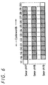
- Fig. 6 illustrates horizontally a specific column of the sector of Fig. 3 in which a burst of errors 12 bytes long has occurred and utilizes the same drawing conventions as in Fig. 5. The burst error appears at bytes 18-29.
- Search area 17 covers 1 byte, 17, free of errors, and 11 bytes, 18-28, in which errors are detected.
- Search area 18 covers zero bytes free of errors and 12 bytes, 18-29, in which errors are detected.
- Search area 19 covers 1 byte, 30, free of errors and 11 bytes, 19-29, in which errors are detected.
- step S1 begins and proceeds to step S2 whereat, data from a sector of the disk is read from the disk, processed, and supplied to decoder 67 for error correction processing.
- step S3 decoder 67 detects and attempts to correct errors found in the data with the CRC and RS parity information. Typically, only errors less than nine bytes in length are fully corrected.
- step S4 the data corrected in step S3 is tested to determine whether it is fully corrected. If the data is correct, this inquiry is answered in the affirmative and processing of the sector is complete as indicated by end step S8. If the data is incorrect, inquiry S4 is answered in the negative and operation of the decoder proceeds to step S5 in which the decoder searches the sector for burst errors and corrects the burst errors where possible.
- inquiry S6 the data corrected in step S5 is tested to determine whether it is fully corrected. If the data now is correct, inquiry S6 is answered in the affirmative and processing of the sector is complete, as indicated by end step S8. If the data still is incorrect, the errors in the data are deemed uncorrectable in step S7 and processing is terminated in step S8.
- step S7 CPU 60 may retrieve an error message stored in ROM 62 and supply the error message to computer 32. Such an error message may include text which is displayed to a user.
- Fig. 8 illustrates a portion of the sector map of Fig. 3 comprising the U.D. and CRC areas (0, 128) - (15, 130), in which the U.D. bytes have been labeled P1-P40.
- these areas are utilized for storing additional error-detecting parity data such as that created by (114, 112, 3) RS coding and (130, 128, 3) RS coding.
- pairs of error-detecting parity bytes are generated for groups of seven or eight codewords of data.
- Such additional parity data is especially useful in connection with read-only disks or read-only portions of disks.
- an entire sector or at least an entire "column" of a sector is searched for burst errors during the search operation.
- Such processing is time-consuming.
- By recording bytes P1-P40 with additional parity data corresponding to specified portions of the sector those portions in which burst errors may have occurred can be more precisely identified.
- the searching process can be limited to those identified portions. Considerable processing time can be saved by limiting the searching process in this manner.
- bytes P1-P40 are recorded with additional parity data pertaining to a sector other than the sector in which bytes P1-P40 are located, preferably an adjacent sector.
- additional parity data pertaining to a sector other than the sector in which bytes P1-P40 are located, preferably an adjacent sector.
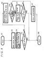
- FIG. 9 A flow diagram of the operation of decoder 67, as controlled by CPU 60, is provided in Fig. 9. Steps S1-S8 of Fig. 9 are substantially identical to those of Fig. 7 and thus will not be described further hereinbelow. Following a negative response to inquiry S4, processing proceeds to step S9 where decoder 67 processes the sector with error-detecting parity data P1-P40 to determine the general location of a burst error. For each portion in which an error is detected, decoder 67 generates an error flag.
- decoder 67 determines whether error flags were generated in a predetermined number of successive portions of the sector.
- the predetermined number is three. If errors occurred in the predetermined number of successive portions, then processing proceeds with step S5; otherwise, processing proceeds with step S7.
- step S5 the search process previously described is limited to those portions of the sector for which an error flag was generated.
Landscapes
- Engineering & Computer Science (AREA)
- Physics & Mathematics (AREA)
- Signal Processing (AREA)
- Algebra (AREA)
- General Physics & Mathematics (AREA)
- Mathematical Physics (AREA)
- Pure & Applied Mathematics (AREA)
- Probability & Statistics with Applications (AREA)
- Theoretical Computer Science (AREA)
- Error Detection And Correction (AREA)
- Detection And Correction Of Errors (AREA)
- Signal Processing For Digital Recording And Reproducing (AREA)
Applications Claiming Priority (2)
| Application Number | Priority Date | Filing Date | Title |
|---|---|---|---|
| JP258523/94 | 1994-10-24 | ||
| JP25852394A JP3520576B2 (ja) | 1994-10-24 | 1994-10-24 | 誤り訂正方法 |
Publications (2)
| Publication Number | Publication Date |
|---|---|
| EP0709847A2 true EP0709847A2 (de) | 1996-05-01 |
| EP0709847A3 EP0709847A3 (de) | 1998-04-01 |
Family
ID=17321399
Family Applications (1)
| Application Number | Title | Priority Date | Filing Date |
|---|---|---|---|
| EP95307504A Withdrawn EP0709847A3 (de) | 1994-10-24 | 1995-10-23 | Digitale Kodierung und Fehlerkorrektur |
Country Status (4)
| Country | Link |
|---|---|
| US (1) | US5781567A (de) |
| EP (1) | EP0709847A3 (de) |
| JP (1) | JP3520576B2 (de) |
| KR (1) | KR100423170B1 (de) |
Families Citing this family (8)
| Publication number | Priority date | Publication date | Assignee | Title |
|---|---|---|---|---|
| KR100548223B1 (ko) * | 1998-07-03 | 2006-03-23 | 삼성전자주식회사 | 자기기록재생기기의 버스트 에러 검출장치 및 검출방법 |
| US6446234B1 (en) * | 1999-03-16 | 2002-09-03 | International Business Machines Corporation | Method and apparatus for updating cyclic redundancy check information for data storage |
| JP4016169B2 (ja) * | 1999-03-30 | 2007-12-05 | ソニー株式会社 | ドライブ装置 |
| JP2000293964A (ja) * | 1999-04-05 | 2000-10-20 | Sony Corp | ドライブ装置 |
| KR100505210B1 (ko) * | 2002-03-12 | 2005-08-04 | 엘지전자 주식회사 | 에러 정정장치 및 방법 |
| US7131052B2 (en) * | 2002-08-12 | 2006-10-31 | International Business Machines Corporation | Algebraic decoder and method for correcting an arbitrary mixture of burst and random errors |
| US7272777B2 (en) * | 2003-06-04 | 2007-09-18 | International Business Machines Corporation | Method for correcting a burst of errors plus random errors |
| EP1526701A1 (de) * | 2003-10-22 | 2005-04-27 | Mitsubishi Denki Kabushiki Kaisha | Verfahren und Vorrichtung zur Uebertragung und Rueckgewinnung von Datenpaketen |
Family Cites Families (8)
| Publication number | Priority date | Publication date | Assignee | Title |
|---|---|---|---|---|
| JP2569478B2 (ja) * | 1986-02-19 | 1997-01-08 | ソニー株式会社 | デ−タ記録装置 |
| US4907215A (en) * | 1986-08-27 | 1990-03-06 | Sony Corporation | Integral optical recording of product code in data areas |
| US4821253A (en) * | 1986-12-19 | 1989-04-11 | Matsushita Electric Industrial Co., Ltd. | Optical disk and optical disk apparatus with error correction |
| US4916701A (en) * | 1988-09-21 | 1990-04-10 | International Business Machines Corporation | Method and system for correcting long bursts of consecutive errors |
| JPH0652630A (ja) * | 1991-03-28 | 1994-02-25 | Sony Corp | データ記録方法 |
| US5526328A (en) * | 1992-01-29 | 1996-06-11 | Matsushita Electric Industrial Co., Ltd. | Recording and reproducing apparatus with varying amounts of data in different tracks |
| US5379305A (en) * | 1992-07-20 | 1995-01-03 | Digital Equipment Corporation | Error correction system with selectable error correction capabilities |
| US5602857A (en) * | 1993-09-21 | 1997-02-11 | Cirrus Logic, Inc. | Error correction method and apparatus |
-
1994
- 1994-10-24 JP JP25852394A patent/JP3520576B2/ja not_active Expired - Fee Related
-
1995
- 1995-10-20 US US08/546,147 patent/US5781567A/en not_active Expired - Lifetime
- 1995-10-23 EP EP95307504A patent/EP0709847A3/de not_active Withdrawn
- 1995-10-24 KR KR1019950037565A patent/KR100423170B1/ko not_active Expired - Fee Related
Non-Patent Citations (1)
| Title |
|---|
| None |
Also Published As
| Publication number | Publication date |
|---|---|
| JP3520576B2 (ja) | 2004-04-19 |
| EP0709847A3 (de) | 1998-04-01 |
| JPH08124317A (ja) | 1996-05-17 |
| KR960015535A (ko) | 1996-05-22 |
| US5781567A (en) | 1998-07-14 |
| KR100423170B1 (ko) | 2004-06-26 |
Similar Documents
| Publication | Publication Date | Title |
|---|---|---|
| CN100474430C (zh) | 用于使用多个交错删除指针来检测和校正错误的装置 | |
| US5517484A (en) | Optical disk and optical disk recording and reproducing apparatus | |
| JP4098245B2 (ja) | 符号化及び復号化の方法 | |
| EP0278700A2 (de) | Fehler-Korrektur-Verfahren und -Vorrichtung | |
| US6311305B1 (en) | Method and system for overriding error correction | |
| US20070011598A1 (en) | Error detection and correction for encoded data | |
| EP0729150B1 (de) | Datenaufzeichnungs-/wiedergabeverfahren, datenwiedergabevorrichtung, und aufzeichnungsmedium | |
| US7047477B2 (en) | Enhanced coding for informed decoders | |
| KR100599225B1 (ko) | 다중워드 정보를 인코딩하는 방법 | |
| US4847705A (en) | Method and apparatus for encoding magnetic disk sector addresses | |
| US20070204188A1 (en) | Error correction method and reproduction apparatus | |
| US5781567A (en) | Digital coding method and apparatus for the correction of burst errors | |
| JP2002279735A (ja) | 誤り訂正方法 | |
| US7340663B2 (en) | Method and apparatus for embedding an additional layer of error correction into an error correcting code | |
| US7131052B2 (en) | Algebraic decoder and method for correcting an arbitrary mixture of burst and random errors | |
| KR100583360B1 (ko) | 워드식 인터리빙 및 오류보호에 의한 다중워드 정보의 인코딩방법, 정보의 디코딩방법, 정보의 인코딩 디코딩 장치, 정보가설치된 기록매체 | |
| JP2735230B2 (ja) | 書き換え形光ディスク装置 | |
| US6694473B1 (en) | Parallel signal decoding method | |
| WO1989010029A1 (en) | Method and apparatus for encoding consisting of forming a codeword by combining a first code sequence with a second code sequence | |
| JPH11238324A (ja) | 光記録媒体及び記録装置 | |
| JP3360681B2 (ja) | 情報記録方法 | |
| JP3360629B2 (ja) | 記録装置および情報記録方法 | |
| JPH11238326A (ja) | 再生装置 | |
| JPH11238322A (ja) | 再生装置 | |
| JPH11238321A (ja) | 記録装置 |
Legal Events
| Date | Code | Title | Description |
|---|---|---|---|
| PUAI | Public reference made under article 153(3) epc to a published international application that has entered the european phase |
Free format text: ORIGINAL CODE: 0009012 |
|
| AK | Designated contracting states |
Kind code of ref document: A2 Designated state(s): DE FR GB NL |
|
| PUAL | Search report despatched |
Free format text: ORIGINAL CODE: 0009013 |
|
| AK | Designated contracting states |
Kind code of ref document: A3 Designated state(s): DE FR GB NL |
|
| 17P | Request for examination filed |
Effective date: 19980825 |
|
| 17Q | First examination report despatched |
Effective date: 19980923 |
|
| STAA | Information on the status of an ep patent application or granted ep patent |
Free format text: STATUS: THE APPLICATION IS DEEMED TO BE WITHDRAWN |
|
| 18D | Application deemed to be withdrawn |
Effective date: 19990406 |