EP0709875B1 - Gasversorgungseinheit für Bearbeitungskammer - Google Patents
Gasversorgungseinheit für Bearbeitungskammer Download PDFInfo
- Publication number
- EP0709875B1 EP0709875B1 EP95307270A EP95307270A EP0709875B1 EP 0709875 B1 EP0709875 B1 EP 0709875B1 EP 95307270 A EP95307270 A EP 95307270A EP 95307270 A EP95307270 A EP 95307270A EP 0709875 B1 EP0709875 B1 EP 0709875B1
- Authority
- EP
- European Patent Office
- Prior art keywords
- processing chamber
- gas
- gas distribution
- ring
- dome
- Prior art date
- Legal status (The legal status is an assumption and is not a legal conclusion. Google has not performed a legal analysis and makes no representation as to the accuracy of the status listed.)
- Expired - Lifetime
Links
Images

Classifications
-
- C—CHEMISTRY; METALLURGY
- C23—COATING METALLIC MATERIAL; COATING MATERIAL WITH METALLIC MATERIAL; CHEMICAL SURFACE TREATMENT; DIFFUSION TREATMENT OF METALLIC MATERIAL; COATING BY VACUUM EVAPORATION, BY SPUTTERING, BY ION IMPLANTATION OR BY CHEMICAL VAPOUR DEPOSITION, IN GENERAL; INHIBITING CORROSION OF METALLIC MATERIAL OR INCRUSTATION IN GENERAL
- C23C—COATING METALLIC MATERIAL; COATING MATERIAL WITH METALLIC MATERIAL; SURFACE TREATMENT OF METALLIC MATERIAL BY DIFFUSION INTO THE SURFACE, BY CHEMICAL CONVERSION OR SUBSTITUTION; COATING BY VACUUM EVAPORATION, BY SPUTTERING, BY ION IMPLANTATION OR BY CHEMICAL VAPOUR DEPOSITION, IN GENERAL
- C23C16/00—Chemical coating by decomposition of gaseous compounds, without leaving reaction products of surface material in the coating, i.e. chemical vapour deposition [CVD] processes
- C23C16/44—Chemical coating by decomposition of gaseous compounds, without leaving reaction products of surface material in the coating, i.e. chemical vapour deposition [CVD] processes characterised by the method of coating
- C23C16/455—Chemical coating by decomposition of gaseous compounds, without leaving reaction products of surface material in the coating, i.e. chemical vapour deposition [CVD] processes characterised by the method of coating characterised by the method used for introducing gases into reaction chamber or for modifying gas flows in reaction chamber
- C23C16/45563—Gas nozzles
- C23C16/4558—Perforated rings
-
- H—ELECTRICITY
- H01—ELECTRIC ELEMENTS
- H01J—ELECTRIC DISCHARGE TUBES OR DISCHARGE LAMPS
- H01J37/00—Discharge tubes with provision for introducing objects or material to be exposed to the discharge, e.g. for the purpose of examination or processing thereof
- H01J37/32—Gas-filled discharge tubes
- H01J37/32431—Constructional details of the reactor
- H01J37/3244—Gas supply means
-
- H—ELECTRICITY
- H01—ELECTRIC ELEMENTS
- H01J—ELECTRIC DISCHARGE TUBES OR DISCHARGE LAMPS
- H01J37/00—Discharge tubes with provision for introducing objects or material to be exposed to the discharge, e.g. for the purpose of examination or processing thereof
- H01J37/32—Gas-filled discharge tubes
- H01J37/32431—Constructional details of the reactor
- H01J37/3244—Gas supply means
- H01J37/32449—Gas control, e.g. control of the gas flow
Definitions
- This invention relates to the routing and distribution of process gas as it flows into a processing chamber to react with the surface of a substrate being processed and in particular to structures used to route and distribute process gas about a plasma etch chamber.
- process gases are introduced which are intended to affect the substrate to be processed in a predictable and repeatable way with a uniform effect across the surface of the substrate.
- the process gas interacts with electrical and magnetic fields to form a plasma which facilitates and accelerates the reaction taking place at the substrate surface.
- Vacuum processing chambers are connected to a vacuum pumping system which continuously evacuates the introduced process gas.
- the vacuum pumping system connects to a pumping channel which wholly or partially surrounds the substrate being processed in an attempt to remove the process gas uniformly from around the substrate.
- a simple pipe nozzle in the side of the processing chamber provides a single vacuum port for the whole processing chamber. The gas flowing from the gas inlet openings to the single vacuum port creates a gas flow pattern within the chamber. Flow patterns/or flow regimes are designed so that they flow across the substrate.
- the goal in processing a substrate is that the process gas promote deposit on or etch of each unit area of the substrate surface equally.
- the molecules of the processing gas must be directed in such a manner that their reactants, whether for deposition or etching, contact the substrate surface generally equally in each unit area of the substrate surface.
- a non-uniform gas flow pattern can create undesirable variations in surface film thickness, which may result in defects.
- substrate processing times are adjusted so that the range of predicted film variations due to non-uniform gas flow patterns are taken into account to assure that film coverage or etching is complete at each film layer.
- the process gas flow pattern is subject to change and evaluation by extensive empirical testing until optimum process parameters and process gas distribution manifold configurations are identified.
- a single gas distribution nozzle pattern is rarely optimal for more than a small range of process conditions.
- the material deposited tends to deposit on or the etch gas etches away the processing chamber surfaces exposed to the plasma, including the surface opening(s) through which the process gas is introduced into the process chamber.
- Metal pieces are generally particularly susceptible to plasma corrosion. Since the openings introducing process gas into the processing chamber act as orifices/restrictions to limit the process gas flow into the chamber, a change in the opening size, due to deposited material or enlargement due to etching, affects the gas flow rate and the gas flow pattern across a substrate being processed.
- the gas supply/distribution manifold needs to be constructed to provide easy access to gas flow passages, especially those openings leading directly into the processing chamber and facing the area in the processing chamber where plasma will be present for easy cleaning and/or replacement of components. Monitoring and cleaning or replacement of worn components will avoid noticeable variations in the gas flow that might alter the predetermined optimum gas flow pattern. Variations in the gas flow pattern must be minimized to provide increased uniformity in the deposition or etching of a substrate surface in the processing chamber.
- Reducing and simplifying the number of steps and the time needed to clean and/or replace those structures in the gas feed system which are subject to deposition and/or etching by virtue of their facing the plasma in the processing chamber would decrease the down time of the system, increase the process chamber throughput, and promote process uniformity across the wafer.
- US-A-5134965 discloses a plasma processing apparatus including a thick quartz cylinder and a quartz ring provided in the inside of a cylinder-shaped plasma chamber.
- a ring-like gas guide groove is formed in the peripheral wall of the plasma chamber and a plurality of gas leading inlets communicating with the gas guide groove are formed at equal circumferential intervals in the outer circumference of the quartz cylinder, so that the gas is led into the gas guide groove through the gas supply pipe from a gas source and is blown out uniformly into the plasma chamber.
- This invention provides a processing chamber gas distribution apparatus comprising a gas distribution ring configured to obstruct a generally annular gas feed channel opening of the processing chamber, wherein said gas distribution ring has a surface facing said opening, and said surface includes a set of grooves which are connected to, and provide a passage between, said opening and said processing chamber.
- the arrangement according to the invention thus provides an easy to clean, easy to optimize, and easy to replace gas distribution ring configured to face the plasma in a substrate processing chamber and thereby overcomes many of the difficulties described above.
- the gas distribution ring may include a series of relieved sections, grooves, or slots having predetermined dimensions which face the processing gas feed channel opening. Gas flows from the process gas feed channel into the slots in the surface of the gas distribution ring which provide a passage out to the processing chamber where the gas communicates with the substrate surface according to the process chamber gas flow pattern.
- the annular process gas feed channel according to the invention may be an annular space between the outside surface of a dome covering the top of the processing chamber and the inside surface of a gas inlet ring.
- the inlet ring includes seals sealing the chamber dome to the walls of the lower section of the processing chamber and includes a gas passage through the inlet ring to an annular space forming the gas feed channel.
- a lower opening of the process gas feed channel faces the gas distribution ring supported on a shelf in the processing chamber wall.
- a lip of the process chamber dome (adjacent to the outside surface of the dome) rests against and is supported by a top surface of the gas distribution ring.
- the gas must flow around the lip of the dome resting on the gas distribution ring.
- the slots in the surface of the gas distribution ring and the end surface of the lip of the dome form a discrete set of passages to convey the process gas from the process gas feed channel to the processing chamber in a particular gas introduction pattern.
- the pattern of grooves in the gas distribution ring can be such that they are equally distributed around the generally circular process chamber with parallel sided type grooves or slots, equally distributed around the processing chamber with expanding slots (fan-shaped-triangle) towards the center of the processing chamber, provided in two sets of slots on opposite sides of the processing chamber such the gas flow sweeps across the substrate being processed generally equally from two opposite sides, or a set of parallel slots generally provided only at one end of the chamber such that there is a continuous gas sheet from that end towards the vacuum system nozzle(s) across a portion of the substrate being processed, or any other flow distribution pattern that can be devised within the constraints of the distribution ring.
- the disclosed configuration according to the invention provides for easy cleaning or replacement of gas inlet and distribution components.
- the gas distribution ring acts as a spacer to separate the dome of the processing chamber from a lower processing chamber facilitating the removal of the dome.
- the gas inlet ring can easily be lifted for access to the gas distribution ring.
- the gas distribution ring once so exposed can be removed, cleaned and replaced or can easily be replaced with a different gas distribution ring having different slot configurations for different process conditions, i.e., different flow rates and/or process gases which might be utilized for different substrate materials and/or to obtain optimization of different preselected process parameters.
- the inlet ring can be replaced, the dome can be re-installed, and a vacuum can be pulled to start the new process.
- Configurations according to the invention overcome many of the difficulties evident in process gas supply systems. Any required changes in the gas distribution flow pattern are easily accommodated. Disassembly and reassembly is easy to acquire whenever gas flow passages need to be cleaned or replaced.
- the dome sealing arrangement is both easily disassembled and well protected from the corrosive chamber atmosphere by being relatively remote therefrom physically, as well as by being positioned adjacent the flow path of incoming process gas well upstream of the gas outlet slot, with a relatively long path length of flowing gas between the dome sealing and the gas outlet slots around a corner from and not directly in view of the ionized gas in the chamber.
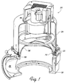
- the upper portion of an etch chamber according to the invention is shown in Figure 1.
- the lower processing chamber section 30 includes a slot opening 22 to provide access to insert or remove substrates from the chamber.
- a piping nozzle 26 connects the process chamber to a vacuum system which evacuates the processing chamber during processing.
- a gas distribution ring 50 is supported by and inset into a shelf in the top circumference in the lower processing chamber section 30.
- An "L" shaped cross section inlet ring 70 is supported on both a land in the wall of the lower processing chamber section 30 and the gas distribution ring 50.
- a continuous processing chamber dome 92 covers the processing chamber and rests on both the inlet ring 70 and the gas distribution ring 50.
- An etch chamber upper assembly 20 above the dome 92 includes an upper housing 24 which surrounds the dome 92 and plasma antenna and other items above the dome.
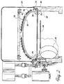
- FIG. 2 shows a side cross section view of an etch processing chamber according to the invention.
- the lower processing chamber section 30 includes a lower processing chamber inner wall 32 which includes the piping nozzle opening 26 to a vacuum system.
- a substrate being processed 44 is supported approximately in the configuration shown by a substrate support pedestal (not shown).
- the upper housing 24 encloses an antenna 38 for activating and supporting a plasma in the processing chamber.
- the antenna 38 includes wire coils 40 mounted on a frame 42 on the outside of the dome 92.
- Process gas is delivered into the processing chamber by a gas passage through the inlet ring 70 and through relieved sections or slots in the top surface of the gas distribution ring 50.
- a nominal gas flow direction as the gas exits the gas distribution ring is shown by the arrows 28 which show the gas flow being directed into the chamber and towards the substrate being processed 44.
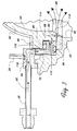
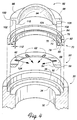
- Figures 3, 4, and 5 show more detail of the various pieces of the processing chamber which provide and distribute process gas to the processing chamber while sealing the processing chamber dome 92 to the lower process chamber section 30.
- Figure 4 provides an exploded view showing the configuration of various pieces as they are assembled. Dashed lines generally provide visual guides and show relationships between adjacent pieces when they are assembled.
- Figure 3 provides a close-up detail of the gas distribution inlet arrangement view of Figure 2, while Figures 4 and 5 generally schematically show the assembly of the pieces shown in Figures 2 and 3.
- the inner wall 32 of the lower processing chamber section 30 includes a distribution ring shelf 34 and inlet ring shelf 36.
- the gas distribution ring 50 includes a bottom surface 52 and an outer surface 56 whose height is generally equal to the height of the wall between the distribution ring shelf 34 and an inlet ring shelf 36 or may better be seen in Figures 5 and 3.
- a series of generally equally spaced slots or grooves or surface relief 62 are provided in the top surface 58 of the gas distribution ring 50. (A generic slot, groove, or surface relief 60 is pictured in Figure 3).
- the "L" shaped inlet ring 70 includes a bottom surface 78 to face both the top surface 58 of the gas distribution ring 50 and the top surface of the inlet ring shelf 36 of the lower processing chamber section 30.
- An O-ring groove 80 is provided in the inlet ring bottom surface 78 and is configured so that when assembled with an O-ring 88 in position, the O-ring 88 seals the joint between the edge of the inlet ring shelf 36 as well as the outer edge of the top surface 58 of the gas distribution ring 50 to the bottom 78 of the inlet ring 70.
- the O-ring 88 sealing across the gap between adjacent pieces provides vacuum sealing and also prevents gas flowing into the processing chamber from seeking a path behind the gas distribution ring 50.
- the outside of the vertical leg of the inlet ring 70 includes an outside circumferential surface 82 which rises vertically to generally match or slightly exceed the height of the edge of the lower processing chamber section 30.
- the top of the horizontal leg of the inlet ring 70 includes a top surface 74 having an O-ring groove 76. When during assembly an O-ring 90 is placed in position in the inlet ring top O-ring groove 76, it seals against a bottom surface 102 of a dome horizontal flange 96 as can be seen in Figures 3 and 5.
- the processing chamber dome 92 includes the dome horizontal flange 96 extending horizontally from the dome around the outer circumference of the dome 92.
- the dome 92 is preferably made of quartz, or alumina, which is compatible with the high temperatures and corrosive atmosphere of the processing chamber.
- the dome horizontal flange 96 is configured so that the dome might be sealed without exposing the seal directly to the corrosive environment of the processing chamber.
- the dome horizontal flange 96 includes a top surface 98, an outside peripheral surface 100, and the bottom sealing surface 102, already mentioned.
- a dome lower lip 104 extends below the bottom of the horizontal flange 96.
- the dome lower lip 104 has an outside peripheral surface 106, a bottom surface 108, and an inner beveled surface 110.
- the configuration of the dome lower lip 104 and the dome horizontal flange 96 is such that when the processing chamber is assembled the bottom surface 108 of the lower lip rests on the top surface 58 of the gas distribution ring 50; and the bottom surface 102 of the horizontal flange 96 of the process chamber dome 92 rests generally on the top surface 74 of the inlet ring 70 so that the top O-ring 90 can seal against the lower side 102 of the dome horizontal flange 96.
- the diametral dimension of the outer surface 106 of the lower lip 104 is smaller than the diametral dimension of the inlet ring inner circumference 72 such that a vertical channel 114 ( Figure 3) is created between the two surfaces having a width 112 (in this example approximately 0.030" or 0.76mm).
- the channel 114 provides a channel opening at its bottom which is covered and thereby obstructed by the gas distribution ring 50.
- a gas inlet block 48 is provided.
- the gas inlet block 48 (connected to a gas inlet piping connection) provides process gas (e.g., BCl 3 ) to the processing chamber. Gas flow into the processing chamber through the gas feed piping is shown by the arrows 45 ( Figure 3).
- the gas inlet piping connection 46 connects to a gas inlet passage 118 in the gas inlet block 48 which is connected and sealed (seal not shown) to the gas passage 116 in the inlet ring 70. Gas flows down through the gas passage 116 at the center of the "L" shaped inlet ring 70 and connects to the vertical annular channel 114.
- Sufficient flow resistance must be provided in the surface slots of the gas distribution ring 50 so that a generally uniform gas pressure is achieved in the gas distribution channel 114 around the periphery of the processing chamber.
- the channel acts as a manifold or reservoir from which the process gas is uniformly discharged through the multitude of gas relief passages (such as 60) in the gas distribution ring 50.
- FIG. 4 Several possible slot or groove configurations in the top of the gas distribution rings 50 are shown in Figures 4, 6, 7, and 8.
- the gas distribution ring 50 of Figures 3 and 4 shows an example of slots 60 with a rounded end configuration 62 generally equally spaced around the edge of the processing chamber such that gas flow into the processing chamber is represented by the arrows 124.
- Figure 5 shows the same arrows 124 representing gas flowing into the center of the processing chamber from generally equally spaced slots 60 in the top of the gas distribution ring 50.
- Figure 6 shows a series of six (for example) parallel slots 67 providing a sheetlike flow from the gas distribution ring 50. If this configuration were placed directly opposite the vacuum system opening into the processing chamber, a generally horizontal linear flow might be expected (however this might not necessarily provide uniform deposition or etching as required by the process). The arrows 126 show the expected direction of flow.
- Figure 7 shows a set of two oppositely spaced slots 66 directing flow as represented by arrows 128 towards the center of the processing chamber from the gas distribution ring 50.
- Figure 8 shows a series of equally distributed fan or isosceles triangle shaped surfaces slots or grooves 64 facing the center of the processing chamber.
- the arrows 130 represent the generally expected configuration of flow from the gas distribution ring 50.
- the fan or isosceles triangle shape of the slots provides a reduced resistance to gas flow toward the center of the processing chamber through these slots when compared with the parallel wall slots 62 of Figure 4.
- the gas flow from the gas inlet piping 46 flows through the gas inlet block to the inlet ring 70.
- the gas feed piping connection 46, inlet block 48, and inlet ring 70 (all preferably made of 316L type stainless steel) direct the process gas flow into the vertical channel 114 having a width 112.
- This vertical channel 114 is generally uniform around the periphery of the processing chamber and rests on the top surface 58 of the gas distribution ring 50. Gas flowing into the channel 114 is distributed around the periphery of the processing chamber and finds its way to the grooves or surface relief 60 in the top 58 of the gas distribution ring 50.
- the dimensions of the surface relief 60 are generally rectangular.
- the O-rings 88 and 90 are generally made of Viton TM , Kalrez TM or Chemraz TM .
- the process chamber dome 92 is generally made of ceramic (preferably alumina or quartz) and the gas distribution ring 50 is also preferably made of a ceramic (for example, alumina).
- the inside of the processing chamber 32 is preferably anodized aluminum. In this configuration all internal process chamber surfaces potentially exposed to the plasma within the processing chamber are highly resistant to corrosion from the process plasma (a plasma of boron trichloride (BCl 3 ) is often used).
- the end of the slot 60 is exposed to the high temperature corrosive environment of the processing chamber thus shielding the stainless steel inlet ring 70 from the high temperature plasma etch gas in the processing chamber.
- all that needs to be done is to raise the processing chamber dome 92 and the inlet ring 70 to provide access to the gas distribution ring 50.
- the gas distribution ring can then easily be reconfigured or replaced as needed to change the flow regime in the processing chamber.
- the gas distribution ring 50 is simply configured so that a conventional machine operation (i.e., grinding) of the surface of the ceramic material of an unslotted gas distribution ring is all that is needed to change or adjust the flow configuration in the processing chamber.
- the number, location and dimension of passages may be easily created or adjusted in standard uncut gas distribution rings to improve uniformity of deposition or etching of a substrate being processed or to provide any number of standard predetermined flow regime choices.
- the dome sealing not only is configured to avoid any direct exposure to the corrosive procession environments but also is further protected by being placed well upstream of gas outlet slots 60 and this with a relatively long column of incoming flowing gas between the dome sealing and the corrosive processing environment.
Landscapes
- Chemical & Material Sciences (AREA)
- Engineering & Computer Science (AREA)
- Physics & Mathematics (AREA)
- Analytical Chemistry (AREA)
- Plasma & Fusion (AREA)
- Materials Engineering (AREA)
- Metallurgy (AREA)
- Organic Chemistry (AREA)
- Mechanical Engineering (AREA)
- Chemical Kinetics & Catalysis (AREA)
- General Chemical & Material Sciences (AREA)
- Drying Of Semiconductors (AREA)
- Signal Processing For Digital Recording And Reproducing (AREA)
- Other Investigation Or Analysis Of Materials By Electrical Means (AREA)
- Plasma Technology (AREA)
- ing And Chemical Polishing (AREA)
Claims (15)
- Gasverteilungsvorrichtung für eine Behandlungskammer mit einem Gasverteilungsring (50), der so gestaltet ist, daß er eine insgesamt ringförmige Öffnung eines Gasbeschikkungskanals (114) der Behandlungskammer blockiert, wobei der Gasverteilungsring eine Fläche (58) hat, die der Öffnung zugewandt ist, dadurch gekennzeichnet, daß die Fläche einen Satz von Nuten (62) aufweist, die mit der Öffnung und der Behandlungskammer verbunden sind und einen Kanal zwischen ihnen bilden.
- Gasverteilungsvorrichtung für eine Behandlungskammer nach Anspruch 1, dadurch gekennzeichnet, daß der Satz von Nuten insgesamt gleich über die Behandlungskammer verteilt ist.
- Gasverteilungsvorrichtung für eine Behandlungskammer nach Anspruch 1, dadurch gekennzeichnet, daß der Satz von Nuten entsprechend einem vorgegebenen Muster geschaffen wird, wobei der Satz von Nuten nicht insgesamt gleich über die Behandlungskammer verteilt ist.
- Gasverteilungsvorrichtung für eine Behandlungskammer nach Anspruch 1, dadurch gekennzeichnet, daß die Nuten (62) zu einem Mittenabschnitt der Behandlungskammer insgesamt offen sind und Kanäle bilden, die Durchflußverengungen für einen Gasstrom verursachen, der aus den Nuten (62) in andere Richtungen als zu dem Mittenabschnitt der Behandlungskammer austritt, so daß ein wesentlicher Teil des durch die Nuten hindurchgehenden Gasstroms zu dem Mittenabschnitt der Kammer und ein vernachlässigbarer Teil des durch die Nuten gehenden Gasstroms in anderen Richtungen als zu dem Mittenabschnitt der Kammer geleitet wird.
- Gasverteilungsvorrichtung für eine Behandlungskammer nach Anspruch 4, dadurch gekennzeichnet, daß jede der Nuten die Kanalöffnung mit einer inneren Umfangsfläche (54) des Rings verbindet.
- Gasverteilungsvorrichtung für eine Behandlungskammer nach Anspruch 1, dadurch gekennzeichnet, daß die Kammer einen Domabschnitt (92) und einen den Domabschnitt umgebenden Gasbeschickungsring (70) hat, wobei die insgesamt ringförmige Gasbeschickungskanalöffnung zwischen den Rändern gegenüberliegender Wände des Kanals angrenzend an die Öffnung gebildet wird, eine erste Wand der gegenüberliegenden Wände eine Fläche (106) des Domabschnitts aufweist und eine zweite der gegenüberliegenden Wände eine Fläche (72) des Gasbeschickungsrings (70) hat, so daß die Gasbeschickungskanalöffnung zwischen dem Rand der Fläche (106) des Domabschnitts und dem Rand der Fläche (72) des Gasbeschickungsrings gebildet wird.
- Gasverteilungsvorrichtung für eine Behandlungskammer nach Anspruch 6, dadurch gekennzeichnet, daß der Gasverteilungsring (50) als eine Distanzeinrichtung wirkt, um den Domabschnitt der Behandlungskammer von einer unteren Behandlungskammerwand zu trennen, so daß nur ein Teil (54) des Rings dem Gas in der Behandlungskammer offen ausgesetzt ist.
- Gasverteilungsvorrichtung für eine Behandlungskammer nach Anspruch 1, welche weiterhineinen Kammerdomabschnitt (92) mit einer Außenfläche (106), die einen Umfang des Domabschnitts umschließt, wobei die Außenfläche durch einen ersten Satz von vorgegebenen Abmessungen von einem Zentrum der Kammer aus bestimmt ist, undeinen Gasbeschickungsring (70) mit einer inneren Fläche (72) aufweist, der der Außenfläche (106) des Kammerdomabschnitts zugewandt und im Abstand zu ihr angeordnet ist, um den insgesamt ringförmigen Gasbeschickungskanal (114) zwischen der inneren Fläche und der äußeren Fläche zu bilden, wobei der Gasbeschickungsring Dichtungseinrichtungen (88, 90) für eine Abdichtung zwischen dem Kammerdomabschnitt (92) und einer Umfangswand (30) der Behandlungskammer und die Umfangswand der Behandlungskammer eine Flachaussparung (34) hat,wobei der Gasverteilungsring (50) für eine Abstützung in der Flachaussparung (34) gestaltet ist und die Fläche des der Öffnung zugewandten Rings die Oberseite des Rings ist und die Oberseite insgesamt in Kontakt mit dem ringförmigen Gasbeschickungskanal (114) steht.
- Gasverteilungsvorrichtung für eine Behandlungskammer nach Anspruch 8, dadurch gekennzeichnet, daß der Satz von Nuten (62) in der Oberseite des Gasverteilungsrings den Gasstromkanal bildet, der von der Oberfläche der Nuten und dem Rand des Domabschnitts (108) gegenüber den Nuten gebildet wird.
- Gasverteilungsvorrichtung für eine Behandlungskammer nach Anspruch 1, dadurch gekennzeichnet, daß die Behandlungskammer eine erzeugbare Behandlungskammer mit einem Dom ist, um darin ein Substratherstellungsverfahren zu enthalten,wobei der ringförmige Gasbeschickungskanal (114) der Behandlungskammer ein Teil eines Gasverrohrungsweges ist, der geeignet ist, Prozeßgas in die Kammer zu überführen, undwobei die Behandlungskammereine erste ringförmige insgesamt ebene Stirnfläche (108), die den Auslaß des Doms bildet und senkrecht zur Symmetrieachse des Doms ist,eine zweite ringförmige Stirnfläche (106) an dem Dom, die außerhalb der ersten Stirnfläche (108) angeordnet ist und diese schneidet,wobei der Gasverteilungsring (50) koaxial zu der Kammer an dem Auslaß des Doms angeordnet ist und die der Gasbeschickungskanalöffnung zugewandte Fläche eine der beiden ebenen Parallelflächen (52, 58) des Rings ist, von denen eine einen Abschnitt der ersten Stirnfläche (108) des Doms überlappt, während sie sich außerhalb der zweiten Stirnfläche erstreckt, undeinen zweiten Ring (70) aufweist, der eine insgesamt zylindrische innere Fläche (72) hat und koaxial zu dem Dom (92) angeordnet ist, wobei die innere Fläche (72) und die zweite ringförmige Stirnfläche (106) in einer entgegengesetzt weisenden Beziehung stehen, so daß ein begrenzter dünner ringförmiger Raum (114) um diese zweite Stirnfläche gebildet wird, der den ringförmigen Gasbeschickungskanal (114) aufweist, in dem zweiten Ring (70) wenigstens eine Durchgangsöffnung (116) in den ringförmigen Raum (114) ausgebildet und für eine Verbindung mit einer externen Gasquelle (46) geeignet ist, und sich der Satz von Nuten (62) in dem Gasverteilungsring (50) von dem innersten Rand der zugewandten Fläche (58) nach außen für eine Verbindung mit dem ringförmigen Raum (114) erstreckt,wodurch Gas gleichförmig über den inneren Durchlaß (116), den ringförmigen Raum (114) und die Nuten (62) in die Behandlungskammer in einem Muster injiziert werden kann, das durch die Positionen und die Gestaltung der Nuten einstellbar ist.
- Gasverteilungsvorrichtung für eine Behandlungskammer nach Anspruch 10, bei welcher eine erste Druckdichtung (88) zwischen dem Gasverteilungsring (50) und dem zweiten Ring (70) außerhalb des ringförmigen Raums (114) vorgesehen ist, um eine Abdichtung für den ringförmigen Raum stromab von dem Durchlaßauslaß zu schaffen.
- Gasverteilungsvorrichtung für eine Behandlungskammer nach Anspruch 11, bei welcher eine zweite Druckdichtung (90) zwischen einer äußeren Fläche (102) des Doms und dem zweiten Ring (70) außerhalb des ringförmigen Raums (114) sowie gegenüber der ersten Dichtung (88) angeordnet ist, um eine wirksame Abdichtung für den ringförmigen Raum (114) stromauf von dem Durchlaßauslaß zu schaffen.
- Gasverteilungsvorrichtung für eine Behandlungskammer nach Anspruch 10, welche weiterhin einen Kammerdomträger (30) aufweist, der Aussparungen (34, 36) bildet, in welche der Gasverteilungsring (50) und der zweite Ring (70) eingeschlossen und abgestützt sind, wobei der Dom (92) an den Ringen (50, 70) und dem Domträger (30) in gasdichter Beziehung befestigt ist.
- Gasverteilungsvorrichtung für eine Behandlungskammer nach Anspruch 10, bei welcher der Dom (92) an dem zweiten Ring (70) angrenzend an einem Umfang des dünnen ringförmigen Raums (114) und stromauf von der Öffnung des inneren Gasdurchlasses (116) so abgedichtet ist, daß die Abdichtungen des Doms von der Behandlungsumgebung in der Behandlungskammer durch den Druck und den Durchgang des Behandlungsgases getrennt sind, das durch den Kanal (114) und in die Behandlungskammer strömt.
- Gasverteilungsvorrichtung für eine Behandlungskammer nach einem der vorhergehenden Ansprüche, dadurch gekennzeichnet, daß der Gasverteilungsring aus einem keramischen Material aufgebaut ist.
Applications Claiming Priority (2)
| Application Number | Priority Date | Filing Date | Title |
|---|---|---|---|
| US08/329,584 US5597439A (en) | 1994-10-26 | 1994-10-26 | Process gas inlet and distribution passages |
| US329584 | 1994-10-26 |
Publications (2)
| Publication Number | Publication Date |
|---|---|
| EP0709875A1 EP0709875A1 (de) | 1996-05-01 |
| EP0709875B1 true EP0709875B1 (de) | 1998-12-23 |
Family
ID=23286086
Family Applications (1)
| Application Number | Title | Priority Date | Filing Date |
|---|---|---|---|
| EP95307270A Expired - Lifetime EP0709875B1 (de) | 1994-10-26 | 1995-10-13 | Gasversorgungseinheit für Bearbeitungskammer |
Country Status (6)
| Country | Link |
|---|---|
| US (1) | US5597439A (de) |
| EP (1) | EP0709875B1 (de) |
| JP (1) | JPH08239775A (de) |
| KR (1) | KR960014748A (de) |
| AT (1) | ATE175051T1 (de) |
| DE (1) | DE69506831T2 (de) |
Cited By (1)
| Publication number | Priority date | Publication date | Assignee | Title |
|---|---|---|---|---|
| CN107376800A (zh) * | 2014-07-24 | 2017-11-24 | 科闳电子股份有限公司 | 用于等离子反应装置的衬套单元 |
Families Citing this family (136)
| Publication number | Priority date | Publication date | Assignee | Title |
|---|---|---|---|---|
| US5746875A (en) * | 1994-09-16 | 1998-05-05 | Applied Materials, Inc. | Gas injection slit nozzle for a plasma process reactor |
| TW283250B (en) | 1995-07-10 | 1996-08-11 | Watkins Johnson Co | Plasma enhanced chemical processing reactor and method |
| AU3145197A (en) * | 1996-06-28 | 1998-01-21 | Lam Research Corporation | Apparatus and method for high density plasma chemical vapor deposition |
| US6013155A (en) * | 1996-06-28 | 2000-01-11 | Lam Research Corporation | Gas injection system for plasma processing |
| US6184158B1 (en) | 1996-12-23 | 2001-02-06 | Lam Research Corporation | Inductively coupled plasma CVD |
| US6286451B1 (en) * | 1997-05-29 | 2001-09-11 | Applied Materials, Inc. | Dome: shape and temperature controlled surfaces |
| US6042687A (en) * | 1997-06-30 | 2000-03-28 | Lam Research Corporation | Method and apparatus for improving etch and deposition uniformity in plasma semiconductor processing |
| US5903106A (en) * | 1997-11-17 | 1999-05-11 | Wj Semiconductor Equipment Group, Inc. | Plasma generating apparatus having an electrostatic shield |
| US6132552A (en) | 1998-02-19 | 2000-10-17 | Micron Technology, Inc. | Method and apparatus for controlling the temperature of a gas distribution plate in a process reactor |
| US6185839B1 (en) | 1998-05-28 | 2001-02-13 | Applied Materials, Inc. | Semiconductor process chamber having improved gas distributor |
| US6050216A (en) * | 1998-08-21 | 2000-04-18 | M.E.C. Technology, Inc. | Showerhead electrode for plasma processing |
| US6263829B1 (en) | 1999-01-22 | 2001-07-24 | Applied Materials, Inc. | Process chamber having improved gas distributor and method of manufacture |
| US20030155079A1 (en) * | 1999-11-15 | 2003-08-21 | Andrew D. Bailey | Plasma processing system with dynamic gas distribution control |
| US6170432B1 (en) | 2000-01-24 | 2001-01-09 | M.E.C. Technology, Inc. | Showerhead electrode assembly for plasma processing |
| US6237528B1 (en) | 2000-01-24 | 2001-05-29 | M.E.C. Technology, Inc. | Showerhead electrode assembly for plasma processing |
| US6660126B2 (en) * | 2001-03-02 | 2003-12-09 | Applied Materials, Inc. | Lid assembly for a processing system to facilitate sequential deposition techniques |
| JP3447707B2 (ja) * | 2001-03-02 | 2003-09-16 | 三菱電機株式会社 | 熱処理装置およびこれを用いた熱処理方法 |
| US6676760B2 (en) | 2001-08-16 | 2004-01-13 | Appiled Materials, Inc. | Process chamber having multiple gas distributors and method |
| KR100428813B1 (ko) * | 2001-09-18 | 2004-04-29 | 주성엔지니어링(주) | 플라즈마 발생장치 및 이를 이용한 SiO₂박막 식각방법 |
| US6793733B2 (en) | 2002-01-25 | 2004-09-21 | Applied Materials Inc. | Gas distribution showerhead |
| US20040060514A1 (en) * | 2002-01-25 | 2004-04-01 | Applied Materials, Inc. A Delaware Corporation | Gas distribution showerhead |
| US7456116B2 (en) | 2002-09-19 | 2008-11-25 | Applied Materials, Inc. | Gap-fill depositions in the formation of silicon containing dielectric materials |
| US20070212850A1 (en) * | 2002-09-19 | 2007-09-13 | Applied Materials, Inc. | Gap-fill depositions in the formation of silicon containing dielectric materials |
| US7431967B2 (en) * | 2002-09-19 | 2008-10-07 | Applied Materials, Inc. | Limited thermal budget formation of PMD layers |
| US7335609B2 (en) * | 2004-08-27 | 2008-02-26 | Applied Materials, Inc. | Gap-fill depositions introducing hydroxyl-containing precursors in the formation of silicon containing dielectric materials |
| US7141483B2 (en) * | 2002-09-19 | 2006-11-28 | Applied Materials, Inc. | Nitrous oxide anneal of TEOS/ozone CVD for improved gapfill |
| US7316761B2 (en) * | 2003-02-03 | 2008-01-08 | Applied Materials, Inc. | Apparatus for uniformly etching a dielectric layer |
| AT501143B1 (de) * | 2004-05-14 | 2006-11-15 | Hueck Folien Gmbh | Sputterkathode zum einsatz im hochvakuum |
| DE102004029466A1 (de) * | 2004-06-18 | 2006-01-05 | Leybold Optics Gmbh | Medieninjektor |
| US20070212847A1 (en) * | 2004-08-04 | 2007-09-13 | Applied Materials, Inc. | Multi-step anneal of thin films for film densification and improved gap-fill |
| US7642171B2 (en) * | 2004-08-04 | 2010-01-05 | Applied Materials, Inc. | Multi-step anneal of thin films for film densification and improved gap-fill |
| KR100584121B1 (ko) * | 2004-08-14 | 2006-05-30 | 에이피티씨 주식회사 | 3차원 가스유로를 갖는 가스공급장치 및 이를 포함하는식각챔버 |
| US20070108161A1 (en) * | 2005-11-17 | 2007-05-17 | Applied Materials, Inc. | Chamber components with polymer coatings and methods of manufacture |
| US20070281106A1 (en) * | 2006-05-30 | 2007-12-06 | Applied Materials, Inc. | Process chamber for dielectric gapfill |
| JP5074741B2 (ja) * | 2006-11-10 | 2012-11-14 | 株式会社日立ハイテクノロジーズ | 真空処理装置 |
| US8298338B2 (en) * | 2007-12-26 | 2012-10-30 | Samsung Electronics Co., Ltd. | Chemical vapor deposition apparatus |
| JP5164107B2 (ja) * | 2008-07-01 | 2013-03-13 | 株式会社ユーテック | プラズマcvd装置、薄膜の製造方法及び磁気記録媒体の製造方法 |
| KR200475462Y1 (ko) * | 2009-03-27 | 2014-12-03 | 램 리써치 코포레이션 | 플라즈마 처리 장치의 교체 가능한 상부 챔버 섹션 |
| US20100252047A1 (en) | 2009-04-03 | 2010-10-07 | Kirk Seth M | Remote fluorination of fibrous filter webs |
| US9076634B2 (en) * | 2009-09-10 | 2015-07-07 | Lam Research Corporation | Replaceable upper chamber parts of plasma processing apparatus |
| US10283321B2 (en) | 2011-01-18 | 2019-05-07 | Applied Materials, Inc. | Semiconductor processing system and methods using capacitively coupled plasma |
| CN103430285B (zh) | 2011-03-22 | 2016-06-01 | 应用材料公司 | 用于化学气相沉积腔室的衬里组件 |
| US8562785B2 (en) * | 2011-05-31 | 2013-10-22 | Lam Research Corporation | Gas distribution showerhead for inductively coupled plasma etch reactor |
| US9245717B2 (en) | 2011-05-31 | 2016-01-26 | Lam Research Corporation | Gas distribution system for ceramic showerhead of plasma etch reactor |
| US9132436B2 (en) | 2012-09-21 | 2015-09-15 | Applied Materials, Inc. | Chemical control features in wafer process equipment |
| US20140083360A1 (en) * | 2012-09-26 | 2014-03-27 | Applied Materials, Inc. | Process chamber having more uniform gas flow |
| US10316409B2 (en) | 2012-12-21 | 2019-06-11 | Novellus Systems, Inc. | Radical source design for remote plasma atomic layer deposition |
| US9018108B2 (en) | 2013-01-25 | 2015-04-28 | Applied Materials, Inc. | Low shrinkage dielectric films |
| US10256079B2 (en) | 2013-02-08 | 2019-04-09 | Applied Materials, Inc. | Semiconductor processing systems having multiple plasma configurations |
| US20140235069A1 (en) * | 2013-02-15 | 2014-08-21 | Novellus Systems, Inc. | Multi-plenum showerhead with temperature control |
| US9362130B2 (en) | 2013-03-01 | 2016-06-07 | Applied Materials, Inc. | Enhanced etching processes using remote plasma sources |
| US9322097B2 (en) * | 2013-03-13 | 2016-04-26 | Applied Materials, Inc. | EPI base ring |
| US9309598B2 (en) | 2014-05-28 | 2016-04-12 | Applied Materials, Inc. | Oxide and metal removal |
| US9966240B2 (en) | 2014-10-14 | 2018-05-08 | Applied Materials, Inc. | Systems and methods for internal surface conditioning assessment in plasma processing equipment |
| US9355922B2 (en) | 2014-10-14 | 2016-05-31 | Applied Materials, Inc. | Systems and methods for internal surface conditioning in plasma processing equipment |
| US11637002B2 (en) | 2014-11-26 | 2023-04-25 | Applied Materials, Inc. | Methods and systems to enhance process uniformity |
| US10573496B2 (en) | 2014-12-09 | 2020-02-25 | Applied Materials, Inc. | Direct outlet toroidal plasma source |
| US11257693B2 (en) | 2015-01-09 | 2022-02-22 | Applied Materials, Inc. | Methods and systems to improve pedestal temperature control |
| US20160225652A1 (en) | 2015-02-03 | 2016-08-04 | Applied Materials, Inc. | Low temperature chuck for plasma processing systems |
| US9728437B2 (en) | 2015-02-03 | 2017-08-08 | Applied Materials, Inc. | High temperature chuck for plasma processing systems |
| US10023959B2 (en) | 2015-05-26 | 2018-07-17 | Lam Research Corporation | Anti-transient showerhead |
| US9691645B2 (en) | 2015-08-06 | 2017-06-27 | Applied Materials, Inc. | Bolted wafer chuck thermal management systems and methods for wafer processing systems |
| US9741593B2 (en) | 2015-08-06 | 2017-08-22 | Applied Materials, Inc. | Thermal management systems and methods for wafer processing systems |
| US9349605B1 (en) | 2015-08-07 | 2016-05-24 | Applied Materials, Inc. | Oxide etch selectivity systems and methods |
| US10504700B2 (en) | 2015-08-27 | 2019-12-10 | Applied Materials, Inc. | Plasma etching systems and methods with secondary plasma injection |
| TWI689619B (zh) * | 2016-04-01 | 2020-04-01 | 美商應用材料股份有限公司 | 用於提供均勻流動的氣體的設備及方法 |
| US10522371B2 (en) | 2016-05-19 | 2019-12-31 | Applied Materials, Inc. | Systems and methods for improved semiconductor etching and component protection |
| US10504754B2 (en) | 2016-05-19 | 2019-12-10 | Applied Materials, Inc. | Systems and methods for improved semiconductor etching and component protection |
| US9865484B1 (en) | 2016-06-29 | 2018-01-09 | Applied Materials, Inc. | Selective etch using material modification and RF pulsing |
| US10629473B2 (en) | 2016-09-09 | 2020-04-21 | Applied Materials, Inc. | Footing removal for nitride spacer |
| US9934942B1 (en) | 2016-10-04 | 2018-04-03 | Applied Materials, Inc. | Chamber with flow-through source |
| US10546729B2 (en) | 2016-10-04 | 2020-01-28 | Applied Materials, Inc. | Dual-channel showerhead with improved profile |
| US10062579B2 (en) | 2016-10-07 | 2018-08-28 | Applied Materials, Inc. | Selective SiN lateral recess |
| US10163696B2 (en) | 2016-11-11 | 2018-12-25 | Applied Materials, Inc. | Selective cobalt removal for bottom up gapfill |
| US10026621B2 (en) | 2016-11-14 | 2018-07-17 | Applied Materials, Inc. | SiN spacer profile patterning |
| US10604841B2 (en) | 2016-12-14 | 2020-03-31 | Lam Research Corporation | Integrated showerhead with thermal control for delivering radical and precursor gas to a downstream chamber to enable remote plasma film deposition |
| US10566206B2 (en) | 2016-12-27 | 2020-02-18 | Applied Materials, Inc. | Systems and methods for anisotropic material breakthrough |
| US10431429B2 (en) | 2017-02-03 | 2019-10-01 | Applied Materials, Inc. | Systems and methods for radial and azimuthal control of plasma uniformity |
| US10319739B2 (en) | 2017-02-08 | 2019-06-11 | Applied Materials, Inc. | Accommodating imperfectly aligned memory holes |
| US10224224B2 (en) | 2017-03-10 | 2019-03-05 | Micromaterials, LLC | High pressure wafer processing systems and related methods |
| US10943834B2 (en) | 2017-03-13 | 2021-03-09 | Applied Materials, Inc. | Replacement contact process |
| JP7176860B6 (ja) | 2017-05-17 | 2022-12-16 | アプライド マテリアルズ インコーポレイテッド | 前駆体の流れを改善する半導体処理チャンバ |
| US11276590B2 (en) | 2017-05-17 | 2022-03-15 | Applied Materials, Inc. | Multi-zone semiconductor substrate supports |
| US11276559B2 (en) | 2017-05-17 | 2022-03-15 | Applied Materials, Inc. | Semiconductor processing chamber for multiple precursor flow |
| US10622214B2 (en) | 2017-05-25 | 2020-04-14 | Applied Materials, Inc. | Tungsten defluorination by high pressure treatment |
| US10497579B2 (en) | 2017-05-31 | 2019-12-03 | Applied Materials, Inc. | Water-free etching methods |
| US10920320B2 (en) | 2017-06-16 | 2021-02-16 | Applied Materials, Inc. | Plasma health determination in semiconductor substrate processing reactors |
| US10541246B2 (en) | 2017-06-26 | 2020-01-21 | Applied Materials, Inc. | 3D flash memory cells which discourage cross-cell electrical tunneling |
| US10727080B2 (en) | 2017-07-07 | 2020-07-28 | Applied Materials, Inc. | Tantalum-containing material removal |
| US10541184B2 (en) | 2017-07-11 | 2020-01-21 | Applied Materials, Inc. | Optical emission spectroscopic techniques for monitoring etching |
| US10043674B1 (en) | 2017-08-04 | 2018-08-07 | Applied Materials, Inc. | Germanium etching systems and methods |
| US10297458B2 (en) | 2017-08-07 | 2019-05-21 | Applied Materials, Inc. | Process window widening using coated parts in plasma etch processes |
| US10276411B2 (en) | 2017-08-18 | 2019-04-30 | Applied Materials, Inc. | High pressure and high temperature anneal chamber |
| JP6947914B2 (ja) | 2017-08-18 | 2021-10-13 | アプライド マテリアルズ インコーポレイテッドApplied Materials,Incorporated | 高圧高温下のアニールチャンバ |
| CN111095524B (zh) | 2017-09-12 | 2023-10-03 | 应用材料公司 | 用于使用保护阻挡物层制造半导体结构的设备和方法 |
| US10424487B2 (en) | 2017-10-24 | 2019-09-24 | Applied Materials, Inc. | Atomic layer etching processes |
| US10283324B1 (en) | 2017-10-24 | 2019-05-07 | Applied Materials, Inc. | Oxygen treatment for nitride etching |
| KR102585074B1 (ko) | 2017-11-11 | 2023-10-04 | 마이크로머티어리얼즈 엘엘씨 | 고압 프로세싱 챔버를 위한 가스 전달 시스템 |
| JP2021503714A (ja) | 2017-11-17 | 2021-02-12 | アプライド マテリアルズ インコーポレイテッドApplied Materials,Incorporated | 高圧処理システムのためのコンデンサシステム |
| WO2019113478A1 (en) | 2017-12-08 | 2019-06-13 | Lam Research Corporation | Integrated showerhead with improved hole pattern for delivering radical and precursor gas to a downstream chamber to enable remote plasma film deposition |
| US10256112B1 (en) | 2017-12-08 | 2019-04-09 | Applied Materials, Inc. | Selective tungsten removal |
| US10903054B2 (en) | 2017-12-19 | 2021-01-26 | Applied Materials, Inc. | Multi-zone gas distribution systems and methods |
| US11328909B2 (en) | 2017-12-22 | 2022-05-10 | Applied Materials, Inc. | Chamber conditioning and removal processes |
| US10854426B2 (en) | 2018-01-08 | 2020-12-01 | Applied Materials, Inc. | Metal recess for semiconductor structures |
| US10679870B2 (en) | 2018-02-15 | 2020-06-09 | Applied Materials, Inc. | Semiconductor processing chamber multistage mixing apparatus |
| US10964512B2 (en) | 2018-02-15 | 2021-03-30 | Applied Materials, Inc. | Semiconductor processing chamber multistage mixing apparatus and methods |
| TWI766433B (zh) | 2018-02-28 | 2022-06-01 | 美商應用材料股份有限公司 | 形成氣隙的系統及方法 |
| US10593560B2 (en) | 2018-03-01 | 2020-03-17 | Applied Materials, Inc. | Magnetic induction plasma source for semiconductor processes and equipment |
| CN111902929B (zh) | 2018-03-09 | 2025-09-19 | 应用材料公司 | 用于含金属材料的高压退火处理 |
| US10319600B1 (en) | 2018-03-12 | 2019-06-11 | Applied Materials, Inc. | Thermal silicon etch |
| US10497573B2 (en) | 2018-03-13 | 2019-12-03 | Applied Materials, Inc. | Selective atomic layer etching of semiconductor materials |
| US10573527B2 (en) | 2018-04-06 | 2020-02-25 | Applied Materials, Inc. | Gas-phase selective etching systems and methods |
| US10490406B2 (en) | 2018-04-10 | 2019-11-26 | Appled Materials, Inc. | Systems and methods for material breakthrough |
| US10699879B2 (en) | 2018-04-17 | 2020-06-30 | Applied Materials, Inc. | Two piece electrode assembly with gap for plasma control |
| US10886137B2 (en) | 2018-04-30 | 2021-01-05 | Applied Materials, Inc. | Selective nitride removal |
| US10950429B2 (en) | 2018-05-08 | 2021-03-16 | Applied Materials, Inc. | Methods of forming amorphous carbon hard mask layers and hard mask layers formed therefrom |
| US10755941B2 (en) | 2018-07-06 | 2020-08-25 | Applied Materials, Inc. | Self-limiting selective etching systems and methods |
| US10872778B2 (en) | 2018-07-06 | 2020-12-22 | Applied Materials, Inc. | Systems and methods utilizing solid-phase etchants |
| US10672642B2 (en) | 2018-07-24 | 2020-06-02 | Applied Materials, Inc. | Systems and methods for pedestal configuration |
| US10748783B2 (en) | 2018-07-25 | 2020-08-18 | Applied Materials, Inc. | Gas delivery module |
| US10675581B2 (en) | 2018-08-06 | 2020-06-09 | Applied Materials, Inc. | Gas abatement apparatus |
| US11049755B2 (en) | 2018-09-14 | 2021-06-29 | Applied Materials, Inc. | Semiconductor substrate supports with embedded RF shield |
| US10892198B2 (en) | 2018-09-14 | 2021-01-12 | Applied Materials, Inc. | Systems and methods for improved performance in semiconductor processing |
| US11062887B2 (en) | 2018-09-17 | 2021-07-13 | Applied Materials, Inc. | High temperature RF heater pedestals |
| US11417534B2 (en) | 2018-09-21 | 2022-08-16 | Applied Materials, Inc. | Selective material removal |
| US11682560B2 (en) | 2018-10-11 | 2023-06-20 | Applied Materials, Inc. | Systems and methods for hafnium-containing film removal |
| US11121002B2 (en) | 2018-10-24 | 2021-09-14 | Applied Materials, Inc. | Systems and methods for etching metals and metal derivatives |
| KR20210077779A (ko) | 2018-11-16 | 2021-06-25 | 어플라이드 머티어리얼스, 인코포레이티드 | 강화된 확산 프로세스를 사용한 막 증착 |
| US11437242B2 (en) | 2018-11-27 | 2022-09-06 | Applied Materials, Inc. | Selective removal of silicon-containing materials |
| WO2020117462A1 (en) | 2018-12-07 | 2020-06-11 | Applied Materials, Inc. | Semiconductor processing system |
| US11721527B2 (en) | 2019-01-07 | 2023-08-08 | Applied Materials, Inc. | Processing chamber mixing systems |
| US10920319B2 (en) | 2019-01-11 | 2021-02-16 | Applied Materials, Inc. | Ceramic showerheads with conductive electrodes |
| CN113000233B (zh) * | 2019-12-18 | 2022-09-02 | 中微半导体设备(上海)股份有限公司 | 等离子体反应器及其气体喷嘴 |
| US11901222B2 (en) | 2020-02-17 | 2024-02-13 | Applied Materials, Inc. | Multi-step process for flowable gap-fill film |
| US20220084794A1 (en) * | 2020-09-16 | 2022-03-17 | Applied Materials, Inc. | Plasma chamber with a multiphase rotating modulated cross-flow |
| US20250215566A1 (en) * | 2023-12-27 | 2025-07-03 | Applied Materials, Inc. | Process chamber gas supply improvement |
Family Cites Families (8)
| Publication number | Priority date | Publication date | Assignee | Title |
|---|---|---|---|---|
| US4230515A (en) * | 1978-07-27 | 1980-10-28 | Davis & Wilder, Inc. | Plasma etching apparatus |
| US4313783A (en) * | 1980-05-19 | 1982-02-02 | Branson International Plasma Corporation | Computer controlled system for processing semiconductor wafers |
| US4342901A (en) * | 1980-08-11 | 1982-08-03 | Eaton Corporation | Plasma etching electrode |
| US4590042A (en) * | 1984-12-24 | 1986-05-20 | Tegal Corporation | Plasma reactor having slotted manifold |
| US4614639A (en) * | 1985-04-26 | 1986-09-30 | Tegal Corporation | Compound flow plasma reactor |
| JPS63179527A (ja) * | 1987-01-21 | 1988-07-23 | Jeol Ltd | プラズマ発生装置 |
| US5134965A (en) * | 1989-06-16 | 1992-08-04 | Hitachi, Ltd. | Processing apparatus and method for plasma processing |
| US5468298A (en) * | 1994-04-13 | 1995-11-21 | Applied Materials, Inc. | Bottom purge manifold for CVD tungsten process |
-
1994
- 1994-10-26 US US08/329,584 patent/US5597439A/en not_active Expired - Fee Related
-
1995
- 1995-10-13 DE DE69506831T patent/DE69506831T2/de not_active Expired - Fee Related
- 1995-10-13 EP EP95307270A patent/EP0709875B1/de not_active Expired - Lifetime
- 1995-10-13 AT AT95307270T patent/ATE175051T1/de not_active IP Right Cessation
- 1995-10-26 KR KR1019950037258A patent/KR960014748A/ko not_active Abandoned
- 1995-10-26 JP JP7279091A patent/JPH08239775A/ja not_active Withdrawn
Cited By (2)
| Publication number | Priority date | Publication date | Assignee | Title |
|---|---|---|---|---|
| CN107376800A (zh) * | 2014-07-24 | 2017-11-24 | 科闳电子股份有限公司 | 用于等离子反应装置的衬套单元 |
| CN107376800B (zh) * | 2014-07-24 | 2019-11-05 | 科闳电子股份有限公司 | 用于等离子反应装置的衬套单元 |
Also Published As
| Publication number | Publication date |
|---|---|
| EP0709875A1 (de) | 1996-05-01 |
| DE69506831T2 (de) | 1999-05-20 |
| DE69506831D1 (de) | 1999-02-04 |
| US5597439A (en) | 1997-01-28 |
| JPH08239775A (ja) | 1996-09-17 |
| ATE175051T1 (de) | 1999-01-15 |
| KR960014748A (ko) | 1996-05-22 |
Similar Documents
| Publication | Publication Date | Title |
|---|---|---|
| EP0709875B1 (de) | Gasversorgungseinheit für Bearbeitungskammer | |
| EP0702392B1 (de) | Plasmareaktor | |
| TW294820B (en) | Gas distribution apparatus | |
| US5746875A (en) | Gas injection slit nozzle for a plasma process reactor | |
| JP3935552B2 (ja) | 半導体処理チャンバー用リッドアセンブリ | |
| US6190732B1 (en) | Method and system for dispensing process gas for fabricating a device on a substrate | |
| TWI490965B (zh) | 改良的多工件處理室及其裝置與方法 | |
| JP5074741B2 (ja) | 真空処理装置 | |
| US5439524A (en) | Plasma processing apparatus | |
| US6616766B2 (en) | Method and apparatus for providing uniform gas delivery to substrates in CVD and PECVD processes | |
| KR101411674B1 (ko) | 포토레지스트 스트립 및 포스트 금속 식각 패시배이션을 위한 고온 챔버 공정 및 챔버 설계 | |
| US20020072164A1 (en) | Processing chamber with multi-layer brazed lid | |
| JP2009111359A (ja) | 原子層堆積チャンバ及び構成部品 | |
| KR20200029056A (ko) | 처리 챔버를 위한 다중-판 면판 | |
| KR20060096460A (ko) | 배기 개구를 특징으로 하는 가스 분배 샤워헤드 | |
| CN113950543B (zh) | 用于外延腔室的隔热组件 | |
| JP2000294538A (ja) | 真空処理装置 | |
| CN112352302A (zh) | 隔栅中的等离子体后气体注入 | |
| US6709556B2 (en) | Plasma processing apparatus | |
| EP1401013B1 (de) | Plasmaverarbeitungseinrichtung | |
| WO2023287699A1 (en) | Improved showerhead pumping geometry for precursor containment | |
| JP7445428B2 (ja) | パージガス供給手段、除害システム、及び除害システムの修正方法 | |
| US20230265560A1 (en) | Pumping liner and methods of manufacture and use thereof | |
| WO2023064217A1 (en) | Downstream residue management hardware | |
| KR102303066B1 (ko) | 챔버 내부의 유동을 확산시키는 것에 의한 더 낮은 입자 수 및 더 양호한 웨이퍼 품질을 위한 효과적이고 새로운 설계 |
Legal Events
| Date | Code | Title | Description |
|---|---|---|---|
| PUAI | Public reference made under article 153(3) epc to a published international application that has entered the european phase |
Free format text: ORIGINAL CODE: 0009012 |
|
| AK | Designated contracting states |
Kind code of ref document: A1 Designated state(s): AT BE CH DE ES FR GB GR IE IT LI NL SE |
|
| 17P | Request for examination filed |
Effective date: 19961021 |
|
| 17Q | First examination report despatched |
Effective date: 19970626 |
|
| GRAG | Despatch of communication of intention to grant |
Free format text: ORIGINAL CODE: EPIDOS AGRA |
|
| GRAG | Despatch of communication of intention to grant |
Free format text: ORIGINAL CODE: EPIDOS AGRA |
|
| GRAH | Despatch of communication of intention to grant a patent |
Free format text: ORIGINAL CODE: EPIDOS IGRA |
|
| GRAH | Despatch of communication of intention to grant a patent |
Free format text: ORIGINAL CODE: EPIDOS IGRA |
|
| GRAA | (expected) grant |
Free format text: ORIGINAL CODE: 0009210 |
|
| AK | Designated contracting states |
Kind code of ref document: B1 Designated state(s): AT BE CH DE ES FR GB GR IE IT LI NL SE |
|
| PG25 | Lapsed in a contracting state [announced via postgrant information from national office to epo] |
Ref country code: NL Free format text: LAPSE BECAUSE OF FAILURE TO SUBMIT A TRANSLATION OF THE DESCRIPTION OR TO PAY THE FEE WITHIN THE PRESCRIBED TIME-LIMIT Effective date: 19981223 Ref country code: LI Free format text: LAPSE BECAUSE OF FAILURE TO SUBMIT A TRANSLATION OF THE DESCRIPTION OR TO PAY THE FEE WITHIN THE PRESCRIBED TIME-LIMIT Effective date: 19981223 Ref country code: IT Free format text: LAPSE BECAUSE OF FAILURE TO SUBMIT A TRANSLATION OF THE DESCRIPTION OR TO PAY THE FEE WITHIN THE PRESCRIBED TIME-LIMIT;WARNING: LAPSES OF ITALIAN PATENTS WITH EFFECTIVE DATE BEFORE 2007 MAY HAVE OCCURRED AT ANY TIME BEFORE 2007. THE CORRECT EFFECTIVE DATE MAY BE DIFFERENT FROM THE ONE RECORDED. Effective date: 19981223 Ref country code: GR Free format text: LAPSE BECAUSE OF NON-PAYMENT OF DUE FEES Effective date: 19981223 Ref country code: ES Free format text: THE PATENT HAS BEEN ANNULLED BY A DECISION OF A NATIONAL AUTHORITY Effective date: 19981223 Ref country code: CH Free format text: LAPSE BECAUSE OF FAILURE TO SUBMIT A TRANSLATION OF THE DESCRIPTION OR TO PAY THE FEE WITHIN THE PRESCRIBED TIME-LIMIT Effective date: 19981223 Ref country code: BE Free format text: LAPSE BECAUSE OF FAILURE TO SUBMIT A TRANSLATION OF THE DESCRIPTION OR TO PAY THE FEE WITHIN THE PRESCRIBED TIME-LIMIT Effective date: 19981223 Ref country code: AT Free format text: LAPSE BECAUSE OF FAILURE TO SUBMIT A TRANSLATION OF THE DESCRIPTION OR TO PAY THE FEE WITHIN THE PRESCRIBED TIME-LIMIT Effective date: 19981223 |
|
| REF | Corresponds to: |
Ref document number: 175051 Country of ref document: AT Date of ref document: 19990115 Kind code of ref document: T |
|
| REG | Reference to a national code |
Ref country code: CH Ref legal event code: EP |
|
| REF | Corresponds to: |
Ref document number: 69506831 Country of ref document: DE Date of ref document: 19990204 |
|
| REG | Reference to a national code |
Ref country code: IE Ref legal event code: FG4D |
|
| ET | Fr: translation filed | ||
| PG25 | Lapsed in a contracting state [announced via postgrant information from national office to epo] |
Ref country code: SE Free format text: LAPSE BECAUSE OF FAILURE TO SUBMIT A TRANSLATION OF THE DESCRIPTION OR TO PAY THE FEE WITHIN THE PRESCRIBED TIME-LIMIT Effective date: 19990323 |
|
| NLV1 | Nl: lapsed or annulled due to failure to fulfill the requirements of art. 29p and 29m of the patents act | ||
| REG | Reference to a national code |
Ref country code: CH Ref legal event code: PL |
|
| PG25 | Lapsed in a contracting state [announced via postgrant information from national office to epo] |
Ref country code: IE Free format text: LAPSE BECAUSE OF NON-PAYMENT OF DUE FEES Effective date: 19991013 Ref country code: GB Free format text: LAPSE BECAUSE OF NON-PAYMENT OF DUE FEES Effective date: 19991013 |
|
| PLBE | No opposition filed within time limit |
Free format text: ORIGINAL CODE: 0009261 |
|
| STAA | Information on the status of an ep patent application or granted ep patent |
Free format text: STATUS: NO OPPOSITION FILED WITHIN TIME LIMIT |
|
| 26N | No opposition filed | ||
| GBPC | Gb: european patent ceased through non-payment of renewal fee |
Effective date: 19991013 |
|
| PG25 | Lapsed in a contracting state [announced via postgrant information from national office to epo] |
Ref country code: FR Free format text: LAPSE BECAUSE OF NON-PAYMENT OF DUE FEES Effective date: 20000630 |
|
| PG25 | Lapsed in a contracting state [announced via postgrant information from national office to epo] |
Ref country code: DE Free format text: LAPSE BECAUSE OF NON-PAYMENT OF DUE FEES Effective date: 20000801 |
|
| REG | Reference to a national code |
Ref country code: FR Ref legal event code: ST |
|
| REG | Reference to a national code |
Ref country code: IE Ref legal event code: MM4A |