EP0709904A1 - Méthode de formation de cosses métalliques collectrices de courant sur des plaques d'accumulateurs - Google Patents
Méthode de formation de cosses métalliques collectrices de courant sur des plaques d'accumulateurs Download PDFInfo
- Publication number
- EP0709904A1 EP0709904A1 EP95115455A EP95115455A EP0709904A1 EP 0709904 A1 EP0709904 A1 EP 0709904A1 EP 95115455 A EP95115455 A EP 95115455A EP 95115455 A EP95115455 A EP 95115455A EP 0709904 A1 EP0709904 A1 EP 0709904A1
- Authority
- EP
- European Patent Office
- Prior art keywords
- current
- metal strips
- lead
- tin
- plastic network
- Prior art date
- Legal status (The legal status is an assumption and is not a legal conclusion. Google has not performed a legal analysis and makes no representation as to the accuracy of the status listed.)
- Granted
Links
- 238000004519 manufacturing process Methods 0.000 title description 3
- 229910052751 metal Inorganic materials 0.000 claims abstract description 86
- 239000002184 metal Substances 0.000 claims abstract description 85
- 229910052802 copper Inorganic materials 0.000 claims abstract description 16
- 238000005520 cutting process Methods 0.000 claims abstract description 11
- 229910045601 alloy Inorganic materials 0.000 claims abstract description 4
- 239000000956 alloy Substances 0.000 claims abstract description 4
- 238000000034 method Methods 0.000 claims description 47
- 238000002844 melting Methods 0.000 claims description 26
- 238000004080 punching Methods 0.000 claims description 21
- 229910000978 Pb alloy Inorganic materials 0.000 claims description 18
- 230000008018 melting Effects 0.000 claims description 18
- RYGMFSIKBFXOCR-UHFFFAOYSA-N Copper Chemical compound [Cu] RYGMFSIKBFXOCR-UHFFFAOYSA-N 0.000 claims description 15
- 239000010949 copper Substances 0.000 claims description 15
- 238000010438 heat treatment Methods 0.000 claims description 14
- 238000003825 pressing Methods 0.000 claims description 12
- LQBJWKCYZGMFEV-UHFFFAOYSA-N lead tin Chemical compound [Sn].[Pb] LQBJWKCYZGMFEV-UHFFFAOYSA-N 0.000 claims description 10
- 238000000576 coating method Methods 0.000 claims description 8
- 239000011248 coating agent Substances 0.000 claims description 7
- 229910001128 Sn alloy Inorganic materials 0.000 claims description 5
- 238000001465 metallisation Methods 0.000 claims description 4
- 239000000155 melt Substances 0.000 claims description 2
- 238000002604 ultrasonography Methods 0.000 claims description 2
- ATJFFYVFTNAWJD-UHFFFAOYSA-N Tin Chemical compound [Sn] ATJFFYVFTNAWJD-UHFFFAOYSA-N 0.000 claims 8
- 230000001427 coherent effect Effects 0.000 claims 1
- 238000007598 dipping method Methods 0.000 claims 1
- 230000001771 impaired effect Effects 0.000 claims 1
- 230000006698 induction Effects 0.000 claims 1
- 229910020220 Pb—Sn Inorganic materials 0.000 abstract 1
- 238000007747 plating Methods 0.000 description 8
- 239000000463 material Substances 0.000 description 4
- 238000003466 welding Methods 0.000 description 4
- 239000002253 acid Substances 0.000 description 3
- 239000002131 composite material Substances 0.000 description 3
- 239000004020 conductor Substances 0.000 description 3
- 238000000354 decomposition reaction Methods 0.000 description 3
- 238000005476 soldering Methods 0.000 description 3
- 238000005266 casting Methods 0.000 description 2
- 238000005260 corrosion Methods 0.000 description 2
- 230000007797 corrosion Effects 0.000 description 2
- 239000003792 electrolyte Substances 0.000 description 2
- 239000007788 liquid Substances 0.000 description 2
- 239000007858 starting material Substances 0.000 description 2
- 229920003002 synthetic resin Polymers 0.000 description 2
- 239000000057 synthetic resin Substances 0.000 description 2
- UFHFLCQGNIYNRP-UHFFFAOYSA-N Hydrogen Chemical compound [H][H] UFHFLCQGNIYNRP-UHFFFAOYSA-N 0.000 description 1
- 229910020658 PbSn Inorganic materials 0.000 description 1
- 101150071746 Pbsn gene Proteins 0.000 description 1
- 230000015572 biosynthetic process Effects 0.000 description 1
- 238000010924 continuous production Methods 0.000 description 1
- 238000009826 distribution Methods 0.000 description 1
- 230000005611 electricity Effects 0.000 description 1
- 229910052739 hydrogen Inorganic materials 0.000 description 1
- 239000001257 hydrogen Substances 0.000 description 1
- 238000007654 immersion Methods 0.000 description 1
- 238000009434 installation Methods 0.000 description 1
- 229910001092 metal group alloy Inorganic materials 0.000 description 1
- 239000010814 metallic waste Substances 0.000 description 1
- 150000002739 metals Chemical class 0.000 description 1
- 230000004048 modification Effects 0.000 description 1
- 238000012986 modification Methods 0.000 description 1
- 230000035515 penetration Effects 0.000 description 1
- 230000002093 peripheral effect Effects 0.000 description 1
- 239000013502 plastic waste Substances 0.000 description 1
- 239000010819 recyclable waste Substances 0.000 description 1
- 239000007787 solid Substances 0.000 description 1
- 239000013589 supplement Substances 0.000 description 1
- 230000007704 transition Effects 0.000 description 1
- 239000002699 waste material Substances 0.000 description 1
Images


Classifications
-
- H—ELECTRICITY
- H01—ELECTRIC ELEMENTS
- H01M—PROCESSES OR MEANS, e.g. BATTERIES, FOR THE DIRECT CONVERSION OF CHEMICAL ENERGY INTO ELECTRICAL ENERGY
- H01M4/00—Electrodes
- H01M4/02—Electrodes composed of, or comprising, active material
- H01M4/64—Carriers or collectors
- H01M4/82—Multi-step processes for manufacturing carriers for lead-acid accumulators
-
- H—ELECTRICITY
- H01—ELECTRIC ELEMENTS
- H01M—PROCESSES OR MEANS, e.g. BATTERIES, FOR THE DIRECT CONVERSION OF CHEMICAL ENERGY INTO ELECTRICAL ENERGY
- H01M50/00—Constructional details or processes of manufacture of the non-active parts of electrochemical cells other than fuel cells, e.g. hybrid cells
- H01M50/50—Current conducting connections for cells or batteries
- H01M50/531—Electrode connections inside a battery casing
- H01M50/534—Electrode connections inside a battery casing characterised by the material of the leads or tabs
-
- H—ELECTRICITY
- H01—ELECTRIC ELEMENTS
- H01M—PROCESSES OR MEANS, e.g. BATTERIES, FOR THE DIRECT CONVERSION OF CHEMICAL ENERGY INTO ELECTRICAL ENERGY
- H01M50/00—Constructional details or processes of manufacture of the non-active parts of electrochemical cells other than fuel cells, e.g. hybrid cells
- H01M50/50—Current conducting connections for cells or batteries
- H01M50/531—Electrode connections inside a battery casing
- H01M50/536—Electrode connections inside a battery casing characterised by the method of fixing the leads to the electrodes, e.g. by welding
-
- Y—GENERAL TAGGING OF NEW TECHNOLOGICAL DEVELOPMENTS; GENERAL TAGGING OF CROSS-SECTIONAL TECHNOLOGIES SPANNING OVER SEVERAL SECTIONS OF THE IPC; TECHNICAL SUBJECTS COVERED BY FORMER USPC CROSS-REFERENCE ART COLLECTIONS [XRACs] AND DIGESTS
- Y02—TECHNOLOGIES OR APPLICATIONS FOR MITIGATION OR ADAPTATION AGAINST CLIMATE CHANGE
- Y02E—REDUCTION OF GREENHOUSE GAS [GHG] EMISSIONS, RELATED TO ENERGY GENERATION, TRANSMISSION OR DISTRIBUTION
- Y02E60/00—Enabling technologies; Technologies with a potential or indirect contribution to GHG emissions mitigation
- Y02E60/10—Energy storage using batteries
-
- Y—GENERAL TAGGING OF NEW TECHNOLOGICAL DEVELOPMENTS; GENERAL TAGGING OF CROSS-SECTIONAL TECHNOLOGIES SPANNING OVER SEVERAL SECTIONS OF THE IPC; TECHNICAL SUBJECTS COVERED BY FORMER USPC CROSS-REFERENCE ART COLLECTIONS [XRACs] AND DIGESTS
- Y10—TECHNICAL SUBJECTS COVERED BY FORMER USPC
- Y10T—TECHNICAL SUBJECTS COVERED BY FORMER US CLASSIFICATION
- Y10T29/00—Metal working
- Y10T29/49—Method of mechanical manufacture
- Y10T29/49002—Electrical device making
- Y10T29/49117—Conductor or circuit manufacturing
- Y10T29/49204—Contact or terminal manufacturing
- Y10T29/49208—Contact or terminal manufacturing by assembling plural parts
- Y10T29/4921—Contact or terminal manufacturing by assembling plural parts with bonding
- Y10T29/49211—Contact or terminal manufacturing by assembling plural parts with bonding of fused material
- Y10T29/49213—Metal
Definitions
- the invention relates to a method for forming metallic current tabs on an electrode plate, in which at least the area where the current tab is to be formed consists of a plastic network.
- the entire electrode plate preferably consists of a plastic network, as described in DE 39 22 424 C2.
- the current conducting tabs of the electrode plates arranged in parallel and at a distance from one another are generally converted into liquid lead or a liquid lead alloy immersed (eg according to the COS method) in order to electrically connect the current conducting tabs of the individual same-pole electrode plates to one another by means of a lead or lead alloy bridge.
- This known method for the electrical connection of the current conductors is problematic when the base material consists of plastic, in particular a plastic network, as is known from DE 39 22 424 C2.
- the plastic of the plastic network melts and decomposes, so that cavities form inside the lead bridge, into which acid can enter, which causes the the plastic network covering copper corrodes and can also get into the electrolyte, where it reduces the hydrogen overvoltage and thus leads to the failure of the cell.
- the battery cathode grid (JP-A-63-211568) made of synthetic resin film can be coated with synthetic resin, lead or a lead alloy to reduce corrosion. How in particular the lead or lead alloy is applied is not specified.
- the aim of the invention is to provide a method of the type mentioned at the outset, with which a stable, solid and largely metallic current conducting vane can be formed, even with the use of plastic as the base material for the electrode plates and in particular the current conducting vane, to which a current conducting bridge can be formed without problems can be cast on from lead or lead alloy without there being any risk of decomposition or melting of the plastic.
- the idea of the invention is therefore that from both sides of the plastic network, metals made of an alloy melting at a low temperature are pressed against one another under high pressure by clamping the plastic network, as a result of which the metal flows plastically into the interstices of the plastic network despite a relatively low temperature and there is an intimate one Connects with the metal coating of the plastic and the similar metal flowing in from the opposite side.
- the starting material in particular in the area of the current guide vane, is a close-meshed network made of plastic, which is already electrically applied by, in particular, galvanically good conductive metallization, in particular made of copper and is corrosion-resistant by subsequently applying a layer of a lead-tin alloy and / or of lead or a lead alloy.
- the pressed-on metal strips are connected not only through the mesh of the plastic network to themselves, but also to the lead-tin alloy and / or the lead or the lead alloy already present on the copper-plating of the plastic network.
- the plastic network, as well as the metal layers and metal strips applied to it, thus form a uniform composite body, particularly in the area of the current conducting lug.
- the embodiment according to claim 3 is particularly advantageous because the excess metal is thereby recovered as recyclable waste.
- the stamping process also has the advantage that the metal strips, which minimally overlap the plastic flag width, are additionally pressed against one another at the lateral edges due to the shear forces. It is also possible to cut from the outset the metal strips applied to the current guide areas of the plastic network so that they fit exactly on the current guide areas and preferably protrude slightly on all sides in order to completely cover the plastic network on all sides.
- the method according to the invention achieves metallic electrode current vanes with very narrow tolerances with regard to thickness and width, which act on the plastic material to be enveloped before the electrolyte enters protect, are very stable and also allow easy connection to other electrode plates of the same or other cells.
- a continuously operating system In order to be able to carry out the process in an economically sensible manner, a continuously operating system is used two thin metal strips or strips consisting of easily deformable and low-melting metal or metal alloy sandwich-like supplied to the plastic network current conductor area to be reinforced.
- the band of connected electrode plates or grids moving at a continuous feed speed and the metal strips being transported at the same speed are passed under a rotating, heated pressure roller.
- the high pressure and the elevated temperature result in the metal of the metal strips being firmly embedded in the mesh-like electrode plate material.
- a continuous process according to the invention can also be found in claim 7.
- a reinforced and particularly good current-conducting current-conducting tab can also be achieved by the measures of claims 9 to 11. Due to the more intensive copper plating of the plastic network on the current guide vane and in the areas surrounding it, not only is better immediate protection of the underlying plastic network against heating when casting on the Lead bridge achieved, but also a quick dissipation of the heat of the cast lead is achieved in the adjacent areas of the current guide.
- the additional copper plating should preferably take place before the lead-tin and / or lead or lead alloy coating is applied. With a lead or lead alloy coating of 0.5 to 1.0 mm, the additional metal strips could be dispensed with. In the case of thinner lead or lead alloy coatings, the metal strips should also be rolled on.
- the embodiment according to claim 12 has the advantage that twice the amount of electrode plates can be produced per unit of time with the same feed within the pressing and punching device. Furthermore, when the punched-out current conducting lugs are offset in the transport direction and are arranged on the same strip, the waste is reduced in this area.
- the procedure according to claim 13 ensures a particularly secure stitch closure.
- the tin alloy used for the immersion bath should have a melting temperature at which there is no decomposition of the plastic network used, but only melting.
- An accumulator electrode plate produced by the method according to the invention is further claimed.
- the invention also relates to an accumulator electrode plate produced by the method according to the invention.
- the current conducting tabs 11 are later formed on the upper edge strip 18 ′ of the band 18 in FIG. 2.
- the plastic network 12 is preferably already copper-coated according to DE 39 22 424 C2 and provided with a lead-tin and / or lead or lead alloy layer.
- the belt 18 consisting of the plastic network 12 is passed between two correspondingly arranged pressure rollers 15, 16, namely together with two elongated ones fed from below or above Metal strips 13, 14 made of a metal melting at low temperature, such as PbSn.
- the metal strips 13, 14 and the plastic network 12 thus form a sandwich arrangement between the rollers 15, 16.
- the rollers 15, 16 are each provided with a heating device 17 which allows the rollers 15, 16 to be heated to a temperature such that the metal strips 13, 14 soften, but the plastic of the belt 18 is not damaged.
- the two rollers 15, 16 can with high pressure of e.g. 30 bar can be pressed against each other.
- the upper roller can be put into circulation by a motor-gear arrangement 19 such that the sandwich arrangement consisting of the belt 18 and the metal strip 13, 14 is conveyed between the rollers 15, 16 in the direction of arrow F.
- a punching arrangement 22 consisting of a table 20 arranged below the belt 18 and a punching tool 21, which is shown in FIG. 1 during the punching process.
- the punching tool 21 is in a position lifted off the belt 18 in the direction of the arrow p, so that the feed of the belt 18 in the conveying direction F is not impeded by the punching device 22.
- a continuously working punch roll can also be provided.
- the punching device 22 can be extended by cutting tools 23, 30, which extend across the Band 18 or extends along the upper edge of the electrode plates to be formed and is used to cut the band 18 into individual electrode plates 26 (FIG. 3) each having a current-conducting lug 11.
- the cutting tools can also be provided on optionally provided continuously working punching or cutting rollers.
- a compact composite body consisting of the compressed metal strips 13, 14 and the plastic network 12 thus emerges from the pair of rollers 15, 16.
- two further metal strips can be pressed onto this sandwich arrangement by means of a further pair of rollers, not shown in FIGS. 1 and 2.
- this composite body As soon as this composite body has reached the punching device 22, it is brought either very quickly or after briefly stopping the band 18 downwards against the table 20 into the punching position shown in FIG. 1, where the superfluous metal protruding from the front and rear via the current conducting tab 11 is punched away becomes. Simultaneously or beforehand, the cutting tools 23, 30, which are only indicated by dashed lines, are intended to cut the electrode plates 26 to the shape shown in FIG. 3. The separated pairs of metal strips between two successive electrical conductors 11 can be recycled, ie again for the formation of new metal strips 13, 14 are used.
- the punching tool 21 is raised again, so that the feed of the band 18 in the conveying direction F can be continued.
- the punching and cutting tools are preferably implemented by continuously running punching or cutting rollers.
- rollers 15, 16 could also be designed eccentrically, the diameter of the rollers 15, 16 then being chosen such that the roller regions having the greatest radial extent together then form the roller gap , if a plastic network area on which the current-conducting lug 11 is to be formed is currently in the nip.
- a soldering or welding station (not shown in FIGS. 1 and 2) is preferably provided, in which the peripheral edges of the metal strips applied to the conductive tab 11 are locally heated and so tightly connected to one another by soldering or welding, that during later use no acid can penetrate from the outside into the space delimited by the metal strips.
- the heating can be carried out by means of ultrasound or other measures that enable local heating.
- FIG. 3 it is indicated how the current guide vane 11 (FIG. 4) provided with the metal strips 13, 14 and 24, 25, which are only indicated by dashed lines, can subsequently be cast around with a current conducting bridge 28 consisting of lead and indicated by dashed lines. Thereafter, the current-conducting bridge 28 is located only in the upper region of the current-conducting lug 11, as a result of which the heat generated during casting can also be distributed to the regions of the metal strips 13, 14 and 24, 25 that do not come into contact with the molten metal of the current-conducting bridge 28 .
- FIG. 3 in FIG. 3 denotes the area at the foot of the current guide vane 11, along which local heating or welding of the metal strips 13, 14 or 24, 25 provided on opposite sides of the current guide vane 11 takes place. Soldering or welding should also be carried out on the free edges of the current-conducting lug 11.
- the additional copper-plating layer or layers which are preferably applied before the tin-plating and / or lead-coating, not only in the area of the current conducting lug 11, but also in the upper area of the plate part of the electrode plate 26 approximately up to the limit 27 in FIG. 3, wherein a continuous transition from the additional copper plating to the normal copper plating of the majority of the electrode plate 26 is preferred.
- This measure will not only be a better one Distribution of the heat generated when the current-conducting bridge 28 is cast on, but also a lower resistance of the electrode plate 26 in the region of the current-conducting lug 11 and the regions of the electrode plate 26 adjoining its mouth, which is important because the current density during discharge, in particular from starter batteries in these areas.
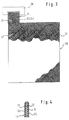
- FIG. 4 shows a cross section of a current guide vane 11, which is provided with metal strips 13, 14 and 24, 25 according to a discontinuous process.
- the metal strips 13, 14 consist of one piece and are wrapped around the upper edge of the plastic network 12 forming the current guide vane 11 and then pressed against one another from both sides.
- a further uniform metal strip is then knocked over, which forms metal strips 24, 25 on both surfaces.
- These metal strips 24, 25 are also pressed from opposite sides against the underlying metal strips 13, 14 and the plastic network 12.
- the individual metal strips 13, 14, 24, 25 are then preferably soldered or locally welded to one another at the initially still open lateral and lower edges.
- FIGS. 5, 5 and 6 show top views of a plastic network double belt 18, which has such a width that two adjacent electrode plates 26, each with a current conducting tab 11, can be formed by a single cutting or punching process.
- the two electrical vanes 11 of a section lie in the conveying direction F one behind the other, while in the embodiment of the method according to FIG.
- the metal strips 13, 14 and 24, 25 are applied analogously to FIGS. 1, 2.
- the mesh size of the plastic network should be 0.5 to 10 mm2 in the flag area.
- the thickness of the copper layer should be 0.01 to 0.5 mm in the flag area and 0.1 to 100 ⁇ m in the remaining plate area.
- the lead-tin layer deposited thereon should have a thickness of 1 to 20 ⁇ m, the lead / lead alloy layer applied thereon a thickness of 0.01 to 1.0 mm, the larger layer thicknesses being required only in the area of the flag.
- the thickness of the applied metal strips 13, 14 should be 3 mm, whereby a total thickness of the current conducting lug 11 of approximately 6 mm is achieved.
Landscapes
- Chemical & Material Sciences (AREA)
- Chemical Kinetics & Catalysis (AREA)
- Electrochemistry (AREA)
- General Chemical & Material Sciences (AREA)
- Connection Of Batteries Or Terminals (AREA)
- Cell Electrode Carriers And Collectors (AREA)
- Fixed Capacitors And Capacitor Manufacturing Machines (AREA)
- Resistance Welding (AREA)
Applications Claiming Priority (2)
| Application Number | Priority Date | Filing Date | Title |
|---|---|---|---|
| DE4435454A DE4435454A1 (de) | 1994-10-04 | 1994-10-04 | Verfahren zum Ausbilden metallischer Stromableitfahnen bei Elektrodenplatten von Akkumulatoren |
| DE4435454 | 1994-10-04 |
Publications (2)
| Publication Number | Publication Date |
|---|---|
| EP0709904A1 true EP0709904A1 (fr) | 1996-05-01 |
| EP0709904B1 EP0709904B1 (fr) | 1998-05-06 |
Family
ID=6529922
Family Applications (1)
| Application Number | Title | Priority Date | Filing Date |
|---|---|---|---|
| EP95115455A Expired - Lifetime EP0709904B1 (fr) | 1994-10-04 | 1995-09-29 | Méthode de formation de cosses métalliques collectrices de courant sur des plaques d'accumulateurs |
Country Status (6)
| Country | Link |
|---|---|
| US (1) | US5848468A (fr) |
| EP (1) | EP0709904B1 (fr) |
| JP (1) | JPH08212998A (fr) |
| AT (1) | ATE165935T1 (fr) |
| DE (2) | DE4435454A1 (fr) |
| ES (1) | ES2116025T3 (fr) |
Families Citing this family (4)
| Publication number | Priority date | Publication date | Assignee | Title |
|---|---|---|---|---|
| US6468830B1 (en) * | 1998-01-26 | 2002-10-22 | Tessera, Inc. | Compliant semiconductor package with anisotropic conductive material interconnects and methods therefor |
| US6475558B2 (en) | 2001-02-26 | 2002-11-05 | Volvo Trucks North America, Inc. | Vehicle electrical ground and process |
| US6825552B2 (en) * | 2001-05-09 | 2004-11-30 | Tessera, Inc. | Connection components with anisotropic conductive material interconnection |
| JP7577457B2 (ja) * | 2020-04-16 | 2024-11-05 | 株式会社イノアックコーポレーション | 防音材及び防音断熱材 |
Citations (4)
| Publication number | Priority date | Publication date | Assignee | Title |
|---|---|---|---|---|
| JPS63211568A (ja) | 1987-02-26 | 1988-09-02 | Matsushita Electric Ind Co Ltd | 密閉形鉛蓄電池用負極格子体 |
| EP0538645A1 (fr) * | 1991-10-23 | 1993-04-28 | VARTA Batterie Aktiengesellschaft | Grille pour électrode négative d'accumulateur au plomb |
| DE4225708C1 (en) * | 1992-08-04 | 1993-09-23 | Deutsche Automobilgesellschaft Mbh, 3300 Braunschweig, De | Porous plate with welded current sink for electrochemical storage cells - enables electrode frame material to well up under pressure of welding and to escape between teeth of current sink |
| DE3922424C2 (de) | 1989-07-07 | 1994-02-03 | Hagen Batterie Ag | Elektrode für elektrochemische Zellen und Verfahren zur Herstellung einer Gitterplatte für eine Elektrode |
Family Cites Families (9)
| Publication number | Priority date | Publication date | Assignee | Title |
|---|---|---|---|---|
| CA1051512A (fr) * | 1973-05-23 | 1979-03-27 | Royce E. Biddick | Electrode bipolaire utilisant un substrat de plastique electriquement conducteur contenant du carbone vitreux |
| DE2330519A1 (de) * | 1973-06-15 | 1975-01-09 | Sen Otto Limmeroth | Leicht-akkumulator |
| DE2710907C3 (de) * | 1977-03-12 | 1979-11-08 | Rheinisch-Westfaelisches Elektrizitaetswerk Ag, 4300 Essen | Metall/Kunststoff-Träger für Elektroden von Akkumulatoren |
| JPS55133770A (en) * | 1979-04-06 | 1980-10-17 | Matsushita Electric Ind Co Ltd | Grid for lead-acid battery and production thereof |
| US4237205A (en) * | 1979-10-22 | 1980-12-02 | General Motors Corporation | Pocket grid for alkaline battery plates |
| FR2520938A1 (fr) * | 1982-02-01 | 1983-08-05 | Europ Accumulateurs | Tissu destine a la fabrication d'une grille pour plaque d'accumulateur, procede de fabrication d'une telle grille, plaque d'accumulateur et accumulateur comportant un tel materiau |
| JPS5983350A (ja) * | 1982-11-05 | 1984-05-14 | Matsushita Electric Ind Co Ltd | 鉛蓄電池用格子 |
| JPS6450362A (en) * | 1987-08-20 | 1989-02-27 | Yuasa Battery Co Ltd | Anode plate of lead storage battery |
| US5580685A (en) * | 1994-09-28 | 1996-12-03 | Venture Enterprises, Incorporated | Multi-layered battery grids and methods of forming battery grids |
-
1994
- 1994-10-04 DE DE4435454A patent/DE4435454A1/de not_active Withdrawn
-
1995
- 1995-09-29 AT AT95115455T patent/ATE165935T1/de not_active IP Right Cessation
- 1995-09-29 ES ES95115455T patent/ES2116025T3/es not_active Expired - Lifetime
- 1995-09-29 US US08/536,316 patent/US5848468A/en not_active Expired - Fee Related
- 1995-09-29 DE DE59502093T patent/DE59502093D1/de not_active Expired - Fee Related
- 1995-09-29 EP EP95115455A patent/EP0709904B1/fr not_active Expired - Lifetime
- 1995-10-04 JP JP7282520A patent/JPH08212998A/ja not_active Withdrawn
Patent Citations (4)
| Publication number | Priority date | Publication date | Assignee | Title |
|---|---|---|---|---|
| JPS63211568A (ja) | 1987-02-26 | 1988-09-02 | Matsushita Electric Ind Co Ltd | 密閉形鉛蓄電池用負極格子体 |
| DE3922424C2 (de) | 1989-07-07 | 1994-02-03 | Hagen Batterie Ag | Elektrode für elektrochemische Zellen und Verfahren zur Herstellung einer Gitterplatte für eine Elektrode |
| EP0538645A1 (fr) * | 1991-10-23 | 1993-04-28 | VARTA Batterie Aktiengesellschaft | Grille pour électrode négative d'accumulateur au plomb |
| DE4225708C1 (en) * | 1992-08-04 | 1993-09-23 | Deutsche Automobilgesellschaft Mbh, 3300 Braunschweig, De | Porous plate with welded current sink for electrochemical storage cells - enables electrode frame material to well up under pressure of welding and to escape between teeth of current sink |
Also Published As
| Publication number | Publication date |
|---|---|
| EP0709904B1 (fr) | 1998-05-06 |
| DE59502093D1 (de) | 1998-06-10 |
| ATE165935T1 (de) | 1998-05-15 |
| JPH08212998A (ja) | 1996-08-20 |
| ES2116025T3 (es) | 1998-07-01 |
| US5848468A (en) | 1998-12-15 |
| DE4435454A1 (de) | 1996-04-11 |
Similar Documents
| Publication | Publication Date | Title |
|---|---|---|
| DE69910500T2 (de) | Stromabnahme über thermisch aufgespritzte Laschen an den Enden einer spiralförmig gerollten elektrochemischen Zelle | |
| DE3312550C3 (de) | Negative Elektrode für Bleiakkumulatoren und Verfahren zu deren Herstellung | |
| DE19626603B4 (de) | Plattierter Werkstoff bzw. Schichtverbundwerkstoff | |
| DE112015000538T5 (de) | Kabelendstück und Struktur zum Verbinden des Kabelendstücks mit einem Aluminiumkabel | |
| DE69023899T2 (de) | Bleisäure-Batterieplatte und Verfahren zu ihrer Herstellung. | |
| DE69110239T2 (de) | Verfahren zur Herstellung einer Elektrode mit leitender Kontaktfläche. | |
| DE112011100268T5 (de) | Verfahren zum Bearbeiten eines Drahtendes | |
| WO2006128203A1 (fr) | Element de connexion electrique | |
| DE69610320T2 (de) | Plattiertes material | |
| DE69919732T2 (de) | Batterieelektrode sowie verfahren und vorrichtung zur herstellung | |
| EP0709904B1 (fr) | Méthode de formation de cosses métalliques collectrices de courant sur des plaques d'accumulateurs | |
| DE102008049220B4 (de) | Halbleiterbauelement mit Kontakten aus einlegierten Metalldrähten | |
| EP3206258A1 (fr) | Système de fabrication d'un raccordement électrique, raccordement électrique et son procédé de fabrication | |
| AT502004A1 (de) | Elektrisches verbindungselement und verfahren zum kontaktieren von elektrischen bauteilen | |
| EP3771042B1 (fr) | Fabrication d'un raccordement plat entre un conducteur électrique et une pièce de contact | |
| DE1614641C2 (de) | Elektrischer Kondensator mit Metallbelegungen aus Aluminium | |
| EP0570662B1 (fr) | Ebauche pour la production de contacts électriques, ainsi que fabrication et utilisation de l'ébauche | |
| DE3406777C2 (de) | Beschichtete Ventilmetallanode zur elektrolytischen Gewinnung von Metallen oder Metalloxiden | |
| DE2550178A1 (de) | Zusammenstellung aus kathode und haengeschiene | |
| DE893989C (de) | Verfahren zum Anschluss einer elektrischen Verbindungsleitung an eine aus einem niedrigschmelzenden Material bestehende Elektrode eines Sperrschichtgleichrichters mittels eines leitenden Haftmittels | |
| EP0726613B1 (fr) | Ebauche et procédé pour la fabrication d'ébauches et de produits semi-finis pour des contacts électriques | |
| DE2941814C2 (de) | Elektrodenplatte mit einem Masseträger aus Streckmetall | |
| DE102020106742A1 (de) | Elektrisches Kontaktteil sowie Verfahren zur Herstellung eines elektrischen Kontaktteils | |
| WO2011003520A1 (fr) | Procédé de fabrication dune cellule électrochimique | |
| DE1014246B (de) | Verfahren zum Widerstandsschweissen von senkrecht aufeinanderstehenden Blechen |
Legal Events
| Date | Code | Title | Description |
|---|---|---|---|
| PUAI | Public reference made under article 153(3) epc to a published international application that has entered the european phase |
Free format text: ORIGINAL CODE: 0009012 |
|
| AK | Designated contracting states |
Kind code of ref document: A1 Designated state(s): AT BE CH DE ES FR GB IT LI NL PT SE |
|
| 17P | Request for examination filed |
Effective date: 19960613 |
|
| 17Q | First examination report despatched |
Effective date: 19970121 |
|
| GRAG | Despatch of communication of intention to grant |
Free format text: ORIGINAL CODE: EPIDOS AGRA |
|
| GRAG | Despatch of communication of intention to grant |
Free format text: ORIGINAL CODE: EPIDOS AGRA |
|
| GRAH | Despatch of communication of intention to grant a patent |
Free format text: ORIGINAL CODE: EPIDOS IGRA |
|
| GRAH | Despatch of communication of intention to grant a patent |
Free format text: ORIGINAL CODE: EPIDOS IGRA |
|
| GRAA | (expected) grant |
Free format text: ORIGINAL CODE: 0009210 |
|
| ITF | It: translation for a ep patent filed | ||
| AK | Designated contracting states |
Kind code of ref document: B1 Designated state(s): AT BE CH DE ES FR GB IT LI NL PT SE |
|
| PG25 | Lapsed in a contracting state [announced via postgrant information from national office to epo] |
Ref country code: NL Free format text: LAPSE BECAUSE OF FAILURE TO SUBMIT A TRANSLATION OF THE DESCRIPTION OR TO PAY THE FEE WITHIN THE PRESCRIBED TIME-LIMIT Effective date: 19980506 |
|
| REF | Corresponds to: |
Ref document number: 165935 Country of ref document: AT Date of ref document: 19980515 Kind code of ref document: T |
|
| REG | Reference to a national code |
Ref country code: CH Ref legal event code: EP |
|
| REF | Corresponds to: |
Ref document number: 59502093 Country of ref document: DE Date of ref document: 19980610 |
|
| ET | Fr: translation filed | ||
| REG | Reference to a national code |
Ref country code: ES Ref legal event code: FG2A Ref document number: 2116025 Country of ref document: ES Kind code of ref document: T3 |
|
| GBT | Gb: translation of ep patent filed (gb section 77(6)(a)/1977) |
Effective date: 19980629 |
|
| PG25 | Lapsed in a contracting state [announced via postgrant information from national office to epo] |
Ref country code: SE Free format text: LAPSE BECAUSE OF FAILURE TO SUBMIT A TRANSLATION OF THE DESCRIPTION OR TO PAY THE FEE WITHIN THE PRESCRIBED TIME-LIMIT Effective date: 19980806 Ref country code: PT Free format text: LAPSE BECAUSE OF FAILURE TO SUBMIT A TRANSLATION OF THE DESCRIPTION OR TO PAY THE FEE WITHIN THE PRESCRIBED TIME-LIMIT Effective date: 19980806 |
|
| PG25 | Lapsed in a contracting state [announced via postgrant information from national office to epo] |
Ref country code: AT Free format text: LAPSE BECAUSE OF NON-PAYMENT OF DUE FEES Effective date: 19980929 |
|
| PG25 | Lapsed in a contracting state [announced via postgrant information from national office to epo] |
Ref country code: ES Free format text: LAPSE BECAUSE OF NON-PAYMENT OF DUE FEES Effective date: 19980930 Ref country code: BE Free format text: LAPSE BECAUSE OF NON-PAYMENT OF DUE FEES Effective date: 19980930 |
|
| NLV1 | Nl: lapsed or annulled due to failure to fulfill the requirements of art. 29p and 29m of the patents act | ||
| PLBE | No opposition filed within time limit |
Free format text: ORIGINAL CODE: 0009261 |
|
| STAA | Information on the status of an ep patent application or granted ep patent |
Free format text: STATUS: NO OPPOSITION FILED WITHIN TIME LIMIT |
|
| BERE | Be: lapsed |
Owner name: HAGEN BATTERIE A.G. Effective date: 19980930 |
|
| 26N | No opposition filed | ||
| PG25 | Lapsed in a contracting state [announced via postgrant information from national office to epo] |
Ref country code: FR Free format text: LAPSE BECAUSE OF NON-PAYMENT OF DUE FEES Effective date: 19990531 |
|
| PG25 | Lapsed in a contracting state [announced via postgrant information from national office to epo] |
Ref country code: DE Free format text: LAPSE BECAUSE OF NON-PAYMENT OF DUE FEES Effective date: 19990701 |
|
| REG | Reference to a national code |
Ref country code: FR Ref legal event code: ST |
|
| PGFP | Annual fee paid to national office [announced via postgrant information from national office to epo] |
Ref country code: GB Payment date: 19990826 Year of fee payment: 5 |
|
| PG25 | Lapsed in a contracting state [announced via postgrant information from national office to epo] |
Ref country code: LI Free format text: LAPSE BECAUSE OF NON-PAYMENT OF DUE FEES Effective date: 19990930 Ref country code: CH Free format text: LAPSE BECAUSE OF NON-PAYMENT OF DUE FEES Effective date: 19990930 |
|
| REG | Reference to a national code |
Ref country code: CH Ref legal event code: PL |
|
| PG25 | Lapsed in a contracting state [announced via postgrant information from national office to epo] |
Ref country code: GB Free format text: LAPSE BECAUSE OF NON-PAYMENT OF DUE FEES Effective date: 20000929 |
|
| GBPC | Gb: european patent ceased through non-payment of renewal fee |
Effective date: 20000929 |
|
| REG | Reference to a national code |
Ref country code: ES Ref legal event code: FD2A Effective date: 19991013 |
|
| PG25 | Lapsed in a contracting state [announced via postgrant information from national office to epo] |
Ref country code: IT Free format text: LAPSE BECAUSE OF NON-PAYMENT OF DUE FEES Effective date: 20050929 |