EP0709927B1 - Assemblage de connecteur - Google Patents
Assemblage de connecteur Download PDFInfo
- Publication number
- EP0709927B1 EP0709927B1 EP95116811A EP95116811A EP0709927B1 EP 0709927 B1 EP0709927 B1 EP 0709927B1 EP 95116811 A EP95116811 A EP 95116811A EP 95116811 A EP95116811 A EP 95116811A EP 0709927 B1 EP0709927 B1 EP 0709927B1
- Authority
- EP
- European Patent Office
- Prior art keywords
- connector
- protrusions
- spring
- locking arm
- receiving space
- Prior art date
- Legal status (The legal status is an assumption and is not a legal conclusion. Google has not performed a legal analysis and makes no representation as to the accuracy of the status listed.)
- Expired - Lifetime
Links
- 238000005452 bending Methods 0.000 claims description 6
- 230000000712 assembly Effects 0.000 description 7
- 238000000429 assembly Methods 0.000 description 7
- 239000012141 concentrate Substances 0.000 description 3
- 239000011347 resin Substances 0.000 description 3
- 229920005989 resin Polymers 0.000 description 3
- 229910000639 Spring steel Inorganic materials 0.000 description 2
- 238000006073 displacement reaction Methods 0.000 description 2
- 239000000463 material Substances 0.000 description 2
- 239000013307 optical fiber Substances 0.000 description 2
- 238000006243 chemical reaction Methods 0.000 description 1
- 239000002131 composite material Substances 0.000 description 1
- 238000010276 construction Methods 0.000 description 1
- 230000000694 effects Effects 0.000 description 1
- 238000003780 insertion Methods 0.000 description 1
- 230000037431 insertion Effects 0.000 description 1
- 230000007774 longterm Effects 0.000 description 1
- 229910052751 metal Inorganic materials 0.000 description 1
- 239000002184 metal Substances 0.000 description 1
- 150000002739 metals Chemical class 0.000 description 1
- 230000003014 reinforcing effect Effects 0.000 description 1
- 238000000926 separation method Methods 0.000 description 1
Images


Classifications
-
- H—ELECTRICITY
- H01—ELECTRIC ELEMENTS
- H01R—ELECTRICALLY-CONDUCTIVE CONNECTIONS; STRUCTURAL ASSOCIATIONS OF A PLURALITY OF MUTUALLY-INSULATED ELECTRICAL CONNECTING ELEMENTS; COUPLING DEVICES; CURRENT COLLECTORS
- H01R13/00—Details of coupling devices of the kinds covered by groups H01R12/70 or H01R24/00 - H01R33/00
- H01R13/62—Means for facilitating engagement or disengagement of coupling parts or for holding them in engagement
- H01R13/627—Snap or like fastening
- H01R13/6271—Latching means integral with the housing
- H01R13/6272—Latching means integral with the housing comprising a single latching arm
Definitions
- This invention relates to a connector assembly with a locking means for connecting electric wires and optical fibers which are especially suited for use with a high-reliability circuit, according to the preamble of claim 1 or 2.
- the spring remains compressed even after the connectors have been coupled together, so that the connector housing tends to suffer creep deformation under the force of the compressed spring.
- connector assemblies disclosed in publications 6 ⁇ to 9 ⁇ are free of creep deformation because the spring is adapted to disengage and return to its rest position. But these connectors are all complicated in structure, and consist of a large number of parts, so that it is troublesome and costly to assemble them.
- a connector assembly is known (US-A-5,183,410) according to the first part of claim 1 or claim 2, in which a kind of plunger/cylinder unit is located inside a housing, which unit is subjected to the pressure of a spring.
- a connecting part When a connecting part is inserted into the housing, a portion of this connecting part exerts pressure on the front portion of the plunger situated in the housing and presses this plunger further into the housing against the spring force.
- a connector assembly Japanese utility model application 5-43484 which includes a spring inside a housing which exerts pressure on a flat part.
- this flat part can be pushed forward and backward and serves to securely hold the parts in their connected state.
- this construction is very complex and incurs high costs, as it is difficult to locate both the spring and the axially displaceable part in a housing in such a way that safe function is guaranteed.
- the displaceable part may be jammed, so full functional safety can not always be guaranteed.
- An object of the present invention is to solve these problems.
- the locking arm is guided upward by the protrusions B and engages the spring (first embodiment), or the resilient arm of the first connector is pushed down by protrusions A and engages the spring (second embodiment).
- the spring is compressed by the second connector.
- the locker arm (in the first embodiment) or the resilient arm (in the second embodiment) resiliently returns to its original position, disengaging from the spring. Namely, the second connector is freed from the force of the spring, so that the connector housing is less likely to suffer creep deformation. This improves the long-term reliability of the connector assembly.
- the locking arm and the protrusions A are integral parts of the second connector.
- the protrusions B and the resilient arm are integral parts of the first connector.
- the spring is the only member that is separate from both connectors. Such a connector assembly, consisting of only three separate members, is easy to assemble and thus can be manufactured at a low cost.
- the protrusions A are guided through such a course that the locking arm or the resilient member will not interfere with the spring.
- the second connector can be pulled out easily and smoothly.
- the connector assembly according to the present invention is especially suited for use with a high-reliability circuit. But it may also be used to fasten or lock seat belts and other belts, bands, cases and other articles for daily use.
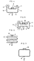
- Fig. 1 shows the connector assembly of the first embodiment.
- This connector assembly comprises a first connector 1 and a second connector 2 both made of a resin. A terminal end of a wire or the ferruled end of an optical fiber is connected to each connector along line C. But since they are not related to the point of the invention, they are not shown for clarity of the figure.
- the first connector 1 comprises a socket-shaped connector housing having a groove 3 for receiving a locking arm 7 (described later), a slit 4 for preventing interference with the locking arm, protrusions B protruding into the groove 3 having predetermined length and thickness, and a spring 6 mounted in a groove 5 formed along the groove 3.
- the second connector 2 has a connector housing to which is integrally connected the locking arm 7 having a free end, that is, a rear end with respect to the direction in which the second connector 2 is inserted into the first connector 1.
- the locking arm 7 has protrusions A formed on side surfaces thereof and adapted to interfere with the protrusions B when the second connector 2 is inserted in the first one 1.
- the protrusions B have their rear ends tapered to guide the protrusions A upward when the second connector 2 is inserted into the first connector 1.
- the protrusions A may be formed on outer side surfaces of the lock arm 7 as shown in Fig. 2A, or on the inner side surfaces of a slit 7b formed in the locking arm as shown in Fig. 2B.
- side surfaces of the locking arm herein used refers to its inner or outer side surface.
- the protrusions B are provided on both sides of a shaft 9 integral with the first connector 1 and adapted to be inserted into the slit 7b.
- the second connector 2 In order to disengage the connectors, the second connector 2 is pulled back while pushing down the free end of the locking arm 7 as shown in Fig. 1D.
- the protrusions A can pass under the protrusions B, so that the spring 6 will not interfere with the locking arm 7, so that the second connector can be pulled out of the first connector without encountering resistance of the spring 6.
- Fig. 3 shows the connector assembly of the second embodiment. It differs from the first embodiment in that the first connector 1 has an integral resilient arm 8 having small protrusions B similar to the protrusions A shown in Fig. 1, that the locking arm 7 has protrusions A having guide surfaces at their front ends for guiding the resilient arm 8 downward when the protrusions A abut the protrusions B, and that the spring 6 is mounted not in the first but in the second connector 2. But this embodiment functions in substantially the same way and achieves substantially the same effect as the first embodiment shown in Fig. 1.
- the protrusions B are guided downward by the tapered surfaces of the protrusions A, so that the resilient arm 8 is pushed down and its rear free end engages the front end of the spring as shown in Fig. 3B.
- the spring 6 is compressed, so that its reactive force acts on the first and second connectors 1 and 2.
- the connectors will be pushed apart by the compressed spring 6.
- the protrusions B will get off from the bottom surfaces of the protrusions A allowing the resilient arm 8 to regain its original position as shown in Fig. 2C.
- the spring 6 disengages from the locking arm 7 and expands. In this state, the protrusions A engage the inner ends of the protrusions B, thereby interlocking the connectors.
- the second connector 2 In order to disengage the connectors, the second connector 2 is pulled back while pushing down the free end of the locking arm 7 as shown in Fig. 2D. When the second connector is pulled back, the protrusions A pass under the protrusions B.
- One advantage of this embodiment is that when inserting the second connector into the first connector, the free end of the locking arm will never rise upward, so that the slit 4 (Fig. 1) for preventing the interference with the locking arm does not have to be formed in the first connector.
- the spring 6 may be a coil spring. But a wire spring or a thin leaf spring that has been deformed to produce repulsive force is more desirable because it requires lesser mounting space.
- Fig. 4 shows a spring which can be used as the spring 6 of the connector assembly according to this invention. It is formed by bending a linear spring material in a single plane so as to start from one end and end at the other end with both ends disposed close to each other. It comprises parallel transverse portions 12 and 13, parallel longitudinal portions 14 disposed at both ends of the transverse portions 12, 13, and U-shaped stress-absobing portions 15 formed by bending one end of each longitudinal portion 14 and connecting this end to the respective ends of the transverse portion 12.
- the spring 11 has a symmetrical configuration as a whole.
- the spring 11 is preferably formed from a spring steel. But it may be formed from any other ordinary spring material, including metals other than spring steel, resins, and composites of resins and reinforcing filaments.
- a wire spring is preferable because it occupies little space. But a strip of spring may be used unless it is too wide.
- the stress-absorbing positions 15 are formed at the two corners of the spring that are farthest from the force application point B, which is at the center of the transverse portion 13.
- the wire shown in Fig. 5 has extra stress-absorbing portions 15 at the other ends of the longitudinal portions 14.
- the springs shown in Figs. 4 and 5 have their ends disposed at the center of the transverse portion 12 and supported at points A on a reaction force bearing member 20. With this arrangement, there is no need to connect one end of the spring to the other. But if the ends of the spring are welded or otherwise connected together, it is possible to position the point(s) of support A and the force application point B the other way around.
- the springs according to the present invention had large spring constants while keeping low degrees of residual deformation.
- the zigzag spring shown in Fig. 6 is so low in spring constant that it cannot reliably push back an article such as a connector to a desired position.
- this zigzag spring has a uniform section, when load W is applied, the maximum bending stress tends to concentrate on the point C, i.e. the point farthest from the load application point B. Thus, the force concentrated on point A can easily exceed the yield point of the spring even if the load applied is small.
- the spring according to the present invention is free of this disadvantage of the rectangular spring (that the degree of residual deformation is large at the corners) while preserving its advantages (that it is thin and high in spring constant). Thus, it shows high repulsive force and can bear a large displacement.
- the spring according to the present invention is basically a rectangular spring with the U-shaped stress-absorbing portions added to some or all of its corners.
- the U-shaped stress-absorbing portions When compressive load is applied to the transverse portions, the U-shaped stress-absorbing portions will narrow by resiliently deforming, so that stress is less likely to concentrate on the ends of the transverse portions. Thus, the degree of residual deformation at the corners can be reduced to a minimum.
- the spring according to the present invention shows a larger repulsive force than the spring shown in Fig. 6 and can bear a larger displacement that the spring shown in Fig. 7.
Landscapes
- Details Of Connecting Devices For Male And Female Coupling (AREA)
Claims (3)
- Ensemble de connecteur comportant :caractérisé en ce quea) un premier connecteur (1);b) un deuxième connecteur (2) formé d'un seul tenant avec un bras de blocage élastiquement déformable (7) et prévu pour être inséré dans ledit premier connecteur (1);c) ledit bras de blocage (7) étant élastiquement déformable vers le haut et vers le bas depuis sa position de repos; etd) ledit premier connecteur (1) étant formé avec un espace de réception de bras de blocage ayant une extrémité ouverte,e) ledit bras de blocage (7) possède des premières saillies (A) sur des surfaces latérales;f) ledit premier connecteur (1) comprend des deuxièmes saillies (B) prévues dans ledit espace de réception de bras de blocage;g) lesdites deuxièmes saillies (B) sont prévues en face desdites premières saillies (A) par rapport à la direction dans laquelle lesdites premières saillies (A) sont insérées, chacune desdites deuxièmes saillies (B) ayant une surface supérieure ayant une première extrémité proche de ladite extrémité ouverte dudit espace de réception de bras de blocage et une deuxième extrémité éloignée de ladite extrémité ouverte, une surface de guidage prévue au niveau de ladite première extrémité, ladite surface de guidage étant inclinée vers le haut vers ladite surface supérieure et se raccordant à ladite surface supérieure, et une surface d'engagement prévue au niveau de ladite deuxième extrémité de ladite surface supérieure;h) ledit bras de blocage (7) est formé avec une partie d'épaulement (7a);i) ledit premier connecteur (1) comprend un ressort (6);j) ledit ressort (6) est prévu pour engager ladite partie d'épaulement (7a) à une extrémité lorsque lesdites premières saillies (A) sont sur les surfaces supérieures desdites deuxièmes saillies (B), afin d'être comprimé lorsque ledit deuxième connecteur (2) est davantage inséré dans ledit premier connecteur (1), et pour se désengager de ladite partie d'épaulement (7a) lorsque lesdites premières saillies (A) engagent lesdites surfaces d'engagement desdites deuxièmes saillies (B); etk) ledit premier connecteur (1) est pourvu sous chacune desdites deuxièmes saillies (B) d'un espace qui permet le passage de la première saillie (A).
- Ensemble de connecteur comportant :caractérisé en ce quea) un premier connecteur (1);b) un deuxième connecteur (2) formé d'un seul tenant avec un bras de blocage élastiquement déformable (7) et prévu pour être inséré dans ledit premier connecteur (1);c) ledit bras de blocage (7) étant élastiquement déformable vers le haut et vers le bas depuis sa position de repos; etd) ledit premier connecteur (1) étant formé avec un espace de réception de bras de blocage ayant une extrémité ouverte,e) ledit bras de blocage (7) possède des premières saillies (A) sur des surfaces latérales;f) ledit premier connecteur (1) est formé d'un seul tenant avec un bras élastique (8) prévu dans ledit espace de réception de bras de blocage et possède des deuxièmes saillies (B);g) ledit bras élastique (8) est élastiquement déformable vers le haut et vers le bas depuis sa position de repos;h) lesdites deuxièmes saillies (B) sont prévues en face desdites premières saillies (A) par rapport à la direction dans laquelle lesdites premières saillies (A) sont insérées, chacune desdites premières saillies (A) ayant une surface inférieure ayant une extrémité avant et une extrémité arrière, une surface de guidage prévue au niveau de ladite extrémité avant et inclinée vers le bas vers ladite surface inférieure et se raccordant à ladite surface inférieure, et une surface d'engagement prévue au niveau de ladite extrémité arrière de ladite surface inférieure;i) ledit deuxième connecteur (2) comprend un ressort (6);j) ledit ressort (6) est prévu pour engager la pointe dudit bras élastique (8) à une extrémité lorsque lesdites deuxièmes saillies (B) sont en contact avec les surfaces inférieures desdites premières saillies (A), afin d'être comprimé lorsque ledit deuxième connecteur (2) est davantage inséré dans ledit premier connecteur (1), et pour se désengager dudit bras élastique (8) lorsque lesdites deuxièmes saillies (B) engagent lesdites surfaces d'engagement desdites premières saillies (A); et k) ledit premier connecteur (1) est pourvu sous chacune desdites deuxièmes saillies (B) d'un espace qui permet le passage de la première saillie (A).
- Ensemble de connecteur selon la revendication 1 ou 2,
caractérisé en ce que
ledit ressort (6) est un élément symétrique formé en pliant un fil dans un plan unique et comporte deux parties transversales parallèles (12, 13), une ayant un point de support et l'autre ayant un point d'application de force, deux parties longitudinales parallèles (14, 14) prévues aux deux extrémités desdites parties transversales (12, 13), et des parties d'absorption de choc en forme de U (15) prévues à au moins une extrémité desdites parties longitudinales (14, 14) et se raccordant aux deux extrémités d'une desdites parties transversales (12, 13).
Applications Claiming Priority (6)
| Application Number | Priority Date | Filing Date | Title |
|---|---|---|---|
| JP26362094 | 1994-10-27 | ||
| JP263620/94 | 1994-10-27 | ||
| JP26362094A JP3378382B2 (ja) | 1994-10-27 | 1994-10-27 | コネクタ |
| JP288096/94 | 1994-11-22 | ||
| JP28809694 | 1994-11-22 | ||
| JP6288096A JPH08145100A (ja) | 1994-11-22 | 1994-11-22 | ば ね |
Publications (3)
| Publication Number | Publication Date |
|---|---|
| EP0709927A2 EP0709927A2 (fr) | 1996-05-01 |
| EP0709927A3 EP0709927A3 (fr) | 1997-01-08 |
| EP0709927B1 true EP0709927B1 (fr) | 1999-06-16 |
Family
ID=26546108
Family Applications (1)
| Application Number | Title | Priority Date | Filing Date |
|---|---|---|---|
| EP95116811A Expired - Lifetime EP0709927B1 (fr) | 1994-10-27 | 1995-10-25 | Assemblage de connecteur |
Country Status (3)
| Country | Link |
|---|---|
| US (1) | US5591042A (fr) |
| EP (1) | EP0709927B1 (fr) |
| DE (1) | DE69510298T2 (fr) |
Families Citing this family (11)
| Publication number | Priority date | Publication date | Assignee | Title |
|---|---|---|---|---|
| JP3155189B2 (ja) * | 1996-02-09 | 2001-04-09 | 住友電装株式会社 | コネクタ |
| US5762514A (en) * | 1997-02-24 | 1998-06-09 | The Whitaker Corporation | Connector with affixable latch member |
| DE19754876C2 (de) * | 1997-12-10 | 1999-11-04 | Siemens Ag | Steckverbindung mit automatischem Ausruf |
| US6017153A (en) * | 1998-05-29 | 2000-01-25 | Lucent Technologies, Inc. | Optical fiber connector with auxiliary spring |
| US6257917B1 (en) | 2000-07-11 | 2001-07-10 | Itt Manufacturing Enterprises, Inc. | Connector latching arrangement |
| DE60301195T2 (de) * | 2003-02-21 | 2006-06-01 | Alcatel | Gerät zum Entrasten eines LC Steckers |
| WO2005011067A1 (fr) * | 2003-07-24 | 2005-02-03 | Nippon Dics Co., Ltd. | Fiche de cable de haut-parleur, borne de haut-parleur conçue pour recevoir cette fiche et systeme de borne de haut-parleur utilisant cette fiche et cette borne |
| US7168972B1 (en) * | 2006-04-26 | 2007-01-30 | Itronix Corporation | Computer interface jack |
| US8062053B2 (en) * | 2009-10-26 | 2011-11-22 | Tyco Electronics Corporation | Electrical connector with offset latch |
| CN104425991B (zh) * | 2014-10-14 | 2016-08-24 | 浙江中杭电子有限公司 | 矩形连接器快速锁紧及解锁结构 |
| EP3297100B1 (fr) | 2016-08-25 | 2021-11-17 | ITT Manufacturing Enterprises LLC | Interconnexion d'étanchéité à profil bas comportant une interface de verrouillage |
Family Cites Families (17)
| Publication number | Priority date | Publication date | Assignee | Title |
|---|---|---|---|---|
| JPS6199381A (ja) | 1984-10-22 | 1986-05-17 | Fujitsu Ltd | 電界効果トランジスタ及びその製造方法 |
| JPS6451276U (fr) | 1987-09-24 | 1989-03-29 | ||
| JPH0319273A (ja) * | 1989-06-15 | 1991-01-28 | Nec Corp | 半導体装置 |
| JPH084022B2 (ja) * | 1989-07-03 | 1996-01-17 | 矢崎総業株式会社 | 電気コネクタの二重ロック機構 |
| JPH0319273U (fr) | 1989-07-06 | 1991-02-26 | ||
| JP2561960B2 (ja) * | 1989-07-18 | 1996-12-11 | 矢崎総業株式会社 | 電気コネクタの嵌合確認装置 |
| JPH0447285A (ja) * | 1990-06-13 | 1992-02-17 | Nec Corp | 着脱式吊下揚収ブイ |
| JP2509743Y2 (ja) | 1990-08-28 | 1996-09-04 | 矢崎総業株式会社 | コネクタ |
| JP2573753B2 (ja) | 1991-04-01 | 1997-01-22 | 矢崎総業株式会社 | コネクタ |
| JP2522324Y2 (ja) * | 1991-06-26 | 1997-01-16 | 矢崎総業株式会社 | コネクタ |
| JPH0553157A (ja) * | 1991-08-28 | 1993-03-05 | Nec Corp | 光制御デバイス |
| JPH0574521A (ja) | 1991-09-13 | 1993-03-26 | Matsushita Electric Works Ltd | 電気接続用コネクター |
| JPH05121121A (ja) | 1991-10-30 | 1993-05-18 | Amp Japan Ltd | 電気コネクタ |
| JPH0543484U (ja) | 1991-11-05 | 1993-06-11 | 日本航空電子工業株式会社 | コネクタ嵌合固定ユニツト |
| JPH086385Y2 (ja) | 1991-12-20 | 1996-02-21 | 日本航空電子工業株式会社 | 完全嵌合コネクタ |
| JP3272050B2 (ja) * | 1992-10-09 | 2002-04-08 | 古河電気工業株式会社 | コネクタ装置 |
| JP2746012B2 (ja) * | 1992-10-21 | 1998-04-28 | 住友電装株式会社 | コネクタ |
-
1995
- 1995-10-25 EP EP95116811A patent/EP0709927B1/fr not_active Expired - Lifetime
- 1995-10-25 DE DE69510298T patent/DE69510298T2/de not_active Expired - Lifetime
- 1995-10-26 US US08/548,472 patent/US5591042A/en not_active Expired - Lifetime
Also Published As
| Publication number | Publication date |
|---|---|
| DE69510298D1 (de) | 1999-07-22 |
| US5591042A (en) | 1997-01-07 |
| DE69510298T2 (de) | 2000-02-17 |
| EP0709927A2 (fr) | 1996-05-01 |
| EP0709927A3 (fr) | 1997-01-08 |
Similar Documents
| Publication | Publication Date | Title |
|---|---|---|
| EP0709927B1 (fr) | Assemblage de connecteur | |
| US5226842A (en) | Female terminal | |
| EP0789425B1 (fr) | Connecteur | |
| US5980336A (en) | Electrical terminal | |
| EP1073923B1 (fr) | Boitier de prise a verrou en porte a faux fixe sur ce dernier pour connecteur de fibres optiques | |
| US6533600B1 (en) | Connector fitting construction | |
| US9190742B2 (en) | Connector assembly with safety spring bar | |
| US11245221B2 (en) | Connection assembly, valve with connection assembly and method of connecting a wire to a crimp connector | |
| EP0769829B1 (fr) | Connecteur électrique pour carte de PC | |
| US5334041A (en) | Device for detachably coupling first and second halves of electric connector | |
| US6332799B1 (en) | Half-fitting prevention connector | |
| US5478263A (en) | Terminal for connector with engaging mechanism | |
| CN118318358A (zh) | 具有锁定系统的插接连接器 | |
| US5186641A (en) | Socket for electric part | |
| US5449298A (en) | Latching system for intermatable connectors | |
| US7040910B2 (en) | Plug type connector | |
| US20110306230A1 (en) | Connector arrangement with mate-assist device | |
| EP0828317B1 (fr) | Connecteur pour substrat | |
| US5672072A (en) | Circuit board electrical connector | |
| US20200328551A1 (en) | Electric terminal housing with a terminal lock | |
| JP3767783B2 (ja) | 半嵌合防止コネクタ | |
| US5490799A (en) | Connector assembly with association indicator | |
| JP3271696B2 (ja) | コネクタ | |
| US4566160A (en) | End release inverse clevis buckle | |
| CN115441225A (zh) | 具有连接器位置保证件和机械辅助件的电连接器 |
Legal Events
| Date | Code | Title | Description |
|---|---|---|---|
| PUAI | Public reference made under article 153(3) epc to a published international application that has entered the european phase |
Free format text: ORIGINAL CODE: 0009012 |
|
| AK | Designated contracting states |
Kind code of ref document: A2 Designated state(s): DE GB |
|
| PUAL | Search report despatched |
Free format text: ORIGINAL CODE: 0009013 |
|
| AK | Designated contracting states |
Kind code of ref document: A3 Designated state(s): DE GB |
|
| 17P | Request for examination filed |
Effective date: 19970219 |
|
| 17Q | First examination report despatched |
Effective date: 19980511 |
|
| GRAG | Despatch of communication of intention to grant |
Free format text: ORIGINAL CODE: EPIDOS AGRA |
|
| GRAG | Despatch of communication of intention to grant |
Free format text: ORIGINAL CODE: EPIDOS AGRA |
|
| GRAH | Despatch of communication of intention to grant a patent |
Free format text: ORIGINAL CODE: EPIDOS IGRA |
|
| GRAH | Despatch of communication of intention to grant a patent |
Free format text: ORIGINAL CODE: EPIDOS IGRA |
|
| GRAA | (expected) grant |
Free format text: ORIGINAL CODE: 0009210 |
|
| AK | Designated contracting states |
Kind code of ref document: B1 Designated state(s): DE GB |
|
| REF | Corresponds to: |
Ref document number: 69510298 Country of ref document: DE Date of ref document: 19990722 |
|
| PLBE | No opposition filed within time limit |
Free format text: ORIGINAL CODE: 0009261 |
|
| STAA | Information on the status of an ep patent application or granted ep patent |
Free format text: STATUS: NO OPPOSITION FILED WITHIN TIME LIMIT |
|
| 26N | No opposition filed | ||
| REG | Reference to a national code |
Ref country code: GB Ref legal event code: IF02 |
|
| PGFP | Annual fee paid to national office [announced via postgrant information from national office to epo] |
Ref country code: GB Payment date: 20101020 Year of fee payment: 16 |
|
| GBPC | Gb: european patent ceased through non-payment of renewal fee |
Effective date: 20111025 |
|
| PG25 | Lapsed in a contracting state [announced via postgrant information from national office to epo] |
Ref country code: GB Free format text: LAPSE BECAUSE OF NON-PAYMENT OF DUE FEES Effective date: 20111025 |
|
| PGFP | Annual fee paid to national office [announced via postgrant information from national office to epo] |
Ref country code: DE Payment date: 20141023 Year of fee payment: 20 |
|
| REG | Reference to a national code |
Ref country code: DE Ref legal event code: R071 Ref document number: 69510298 Country of ref document: DE |