EP0709942B1 - Capuchon de bougie, muni d'une ventilation, pour moteur à combustion interne - Google Patents
Capuchon de bougie, muni d'une ventilation, pour moteur à combustion interne Download PDFInfo
- Publication number
- EP0709942B1 EP0709942B1 EP95401778A EP95401778A EP0709942B1 EP 0709942 B1 EP0709942 B1 EP 0709942B1 EP 95401778 A EP95401778 A EP 95401778A EP 95401778 A EP95401778 A EP 95401778A EP 0709942 B1 EP0709942 B1 EP 0709942B1
- Authority
- EP
- European Patent Office
- Prior art keywords
- plug cap
- vent
- water
- plug
- aperture
- Prior art date
- Legal status (The legal status is an assumption and is not a legal conclusion. Google has not performed a legal analysis and makes no representation as to the accuracy of the status listed.)
- Expired - Lifetime
Links
- 238000002485 combustion reaction Methods 0.000 title claims description 5
- XLYOFNOQVPJJNP-UHFFFAOYSA-N water Substances O XLYOFNOQVPJJNP-UHFFFAOYSA-N 0.000 claims description 27
- 238000007789 sealing Methods 0.000 claims description 6
- 239000013013 elastic material Substances 0.000 claims description 3
- 238000000034 method Methods 0.000 claims description 3
- 239000002245 particle Substances 0.000 claims description 3
- 238000005406 washing Methods 0.000 description 4
- 238000003780 insertion Methods 0.000 description 2
- 230000037431 insertion Effects 0.000 description 2
- 230000035515 penetration Effects 0.000 description 2
- 230000002093 peripheral effect Effects 0.000 description 2
- 230000002411 adverse Effects 0.000 description 1
- 238000010276 construction Methods 0.000 description 1
- 230000000694 effects Effects 0.000 description 1
- 238000000465 moulding Methods 0.000 description 1
Images

Classifications
-
- H—ELECTRICITY
- H01—ELECTRIC ELEMENTS
- H01T—SPARK GAPS; OVERVOLTAGE ARRESTERS USING SPARK GAPS; SPARKING PLUGS; CORONA DEVICES; GENERATING IONS TO BE INTRODUCED INTO NON-ENCLOSED GASES
- H01T13/00—Sparking plugs
- H01T13/02—Details
- H01T13/06—Covers forming a part of the plug and protecting it against adverse environment
Definitions
- the present invention relates to the field of internal combustion engines for vehicles or the like, of the type having an elongated bore for receiving an ignition plug. More particularly, the invention relates to a freely engageable and removable plug cap for closing the opening of such an elongated bore, the plug cap being provided with at least one air vent for evacuating air inside the bore.
- plug cap An example of such a plug cap is described in JP-A-H6-196246(1994).
- the plug cap is traversed by an ignition cable and is freely mountable and removable with respect to an elongated bore that houses an ignition plug.
- the plug cap When fitted into the bore, the plug cap serves to prevent the ingress of water into the bore, and at the same time holds an ignition pipe (also called “plug cap pipe”) firmly in place.
- the plug cap When the engine is running, the air inside the elongated bore is heated and tends to expand, causing the plug cap to lift away and float above the elongated bore. To avoid such phenomenon, the plug cap is provided with one or more vent-holes at its upper face or side face to release the expanded air.
- vent-holes extend upwards or sideways, they are vulnerable to water penetration and thus deteriorate the cap's sealing properties.
- water is sprayed at pressure on such a plug cap, for instance when driving under the rain or washing the car etc., there is always a risk that water penetrates inside the elongated ignition plug bore. When this happens, electrical leakage may occur from the ignition plug through the water. The plug can thereby fail to ignite properly, with adverse effects on the running of the engine.
- a plug cap for sealingly closing an elongated bore housing an ignition plug in an internal combustion engine, said plug cap being traversed by an ignition cable and comprising at least one vent having an aperture for evacuating air inside said elongated bore, characterized in that said vent is provided with a water-tight flap connected to said aperture through a flexible fixing means, the water-tight flap being disposed above the uppermost section of the aperture at a short distance therefrom thereby forming an air slit therebetween so that, in a normal state, said flap is kept open with respect to said aperture and so that in a state where said flap receives a force from water particles said flap closes said aperture by tilting over said aperture with said flexible fixing means acting as a fulcrum.
- the water-tight flap is so configured as to be positioned substantially parallel to the aperture of the vent.
- the fixing means is preferably a flexible hinge.
- the fixing means may be a flexible hinge integrally formed with the plug cap.
- the aperture of the vent is tapered expandingly from the fixing point of the fixing means towards the opposite side, so that, when the water-tight flap is tilted onto the aperture, the flap is tightly superposed on the aperture.
- vent is formed so as to open upwardly towards the outside through the plug cap.
- the plug cap can be made of any elastic material.
- the vent has an outer diameter of approximately 3 mm; the water-tight flap is approximately 0.5 to 2 mm thick; the maximum air slit between the vent and the water-tight flap is approximately 0.3 to 1 mm thick; the hinge portion connecting the vent with the water-tight flap is between 0.3 and 0.5 mm thick; and the hinge portion is between 0.5 and 2.0 mm wide in the circumferential direction.
- the plug cap is fitted onto an elongated bore which comprises the ignition plug on the base thereof; an ignition cable connected to the ignition plug by one end and extending by the other end to the outside of the elongated bore through a hole of the plug cap, and an ignition pipe containing the ignition cable and extending from the ignition plug to the plug cap.
- such plug cap may be used for vehicle engines.
- the vent is provided, at some distance above the aperture thereof, with a freely tiltable water-tight flap which can close off the vent aperture as soon as a water pressure is exerted thereon.
- a freely tiltable water-tight flap which can close off the vent aperture as soon as a water pressure is exerted thereon.
- the water-tight flap closes off the vent under the pressure of the water, thereby preventing the water from entering into the elongated bore for the ignition plug.
- the uppermost section of the vent may be tapered so that the space interposed between the water-tight flap and the vent, expands gradually from their fixing point towards the opposite side. Then, the water-tight flap is more tightly superposed on the vent aperture as soon as the water exerts a pressure thereon, thereby preventing more efficiently the water from entering into elongated bore for the ignition plug.
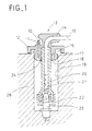
- Fig. 1 shows a plug cap 13 made of an elastic material such as rubber for receiving an ignition cable.
- a peripheral cover 12 is provided around the external circular wall of the plug cap 13. The cover engages with a circular spigot 16 formed on the engine 26 around a rim zone at the opening of an elongated bore 19 that houses an ignition plug.
- the base of the plug cap 13 has a peripheral lip that engages with the wall of the bore near its opening to form a sealing portion 17. The lip is configured to be freely press-fitted inside the bore and removable therefrom.
- the plug cap 13 is provided with a vent 11 which opens upwardly to the outside.
- the upper end of the vent is provided with a water-tight flap 10 which leaves the vent 11 open in the normal state, but closes it when submitted to the impact of water particles.
- the lowermost face of sealing portion 17 facing the base of the bore may optionally be provided with a circumferential groove 18.
- the groove serves to reduce insertion force for fitting the plug cap into the bore and so reduce the compressive strain experienced by the cap around the sealing portion 17 after insertion.
- the lowermost face of the plug cap 13 is also provided with a pipe-holding portion 24 configured to grip firmly the end of the ignition pipe 20 closest to the bore opening.
- the ignition pipe 20 receives a cable 15 for the ignition plug, the cable passing through a cable opening 14 in the plug cap 13 and exiting therefrom towards the outside.
- the other end of the ignition pipe 20 is adapted to mount on the ignition plug 23 at the bottom of the bore 19 via a sealing bushing 22.
- the plug end of the cable 15 is equipped with an electrical contact terminal 21 that lodges inside the ignition pipe 20 and engages with a corresponding contact of the ignition plug 23 to provide the required electrical connection.
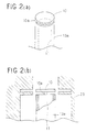
- the vent 11 and the water-tight flap 10 will now be described in detail with reference to Figs. 2(a) and 3(a).
- the vent 11 presents an opening at a top surface portion of the plug cap 13.
- the opening is covered by disc-shaped water-tight flap 10 disposed above the uppermost section of the opening but at a short distance therefrom.
- the water-tight flap 10 has a hinge portion 10a that is integral with the main body 13a of the plug cap, the hinge 10a depending from the latter by at a part on, or adjacent to, its circumference.
- the water-tight flap 10 can be pivoted with the hinge portion 10a serving as a fulcrum point for opening and closing the vent 11.
- the vent 11 and water-tight flap 10a may be formed jointly in a moulding process by using dies 25 as shown in Fig. 2(b).
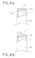
- the vent 11 and the water-tight flap 10 may be formed in a shape shown in Fig. 4(a).
- the uppermost section 11a of the vent 11 is tapered, such that, in a normal state, the space formed between the vent 11 and the water-tight flap 10 expands gradually from the hinge portion 10a to the opposite side.
- the water-tight flap 10 is open, as shown in Fig. 4(a), when water is not sprayed.
- heated air inside the elongated bore 19 is evacuated towards the outside via the space over the vent 11.
- the water-tight flap 10 is pushed down by the pressure of the water, as shown in Fig. 4(b), such that it superposes tightly onto the uppermost section 11a of the vent 11, thereby closing the vent 11. Consequently, water penetration into the elongated ignition plug bore 19 is more efficiently prevented.
Landscapes
- Spark Plugs (AREA)
Claims (10)
- Bouchon de bougie (13) destiné à fermer de façon étanche un alésage allongé (19) renfermant une bougie d'allumage (23) dans un moteur à combustion interne, ledit bouchon de bougie étant traversé par un câble d'allumage (15) et comportant au moins un orifice de mise à l'air libre ayant une ouverture destinée à évacuer l'air à l'intérieur dudit alésage allongé (19), caractérisé en ce que ledit orifice de mise à l'air libre est pourvu d'un volet d'étanchéité à l'eau (10) relié à ladite ouverture par l'intermédiaire de moyens de fixation flexibles (10a), le volet d'étanchéité à l'eau (10) étant disposé au-dessus de la section supérieure de l'ouverture à une courte distance de celle-ci en formant ainsi une fente d'air entre eux de sorte que, dans un état normal, ledit volet est maintenu ouvert par rapport à ladite ouverture et de sorte que, dans un état où ledit volet reçoit une force provenant de particules d'eau, ledit volet ferme ladite ouverture en basculant au-dessus de ladite ouverture avec lesdits moyens de fixation flexibles servant de point d'articulation.
- Bouchon de bougie (13) selon la revendication 1, dans lequel le volet d'étanchéité à l'eau (10) est configuré de façon à être positionné sensiblement parallèlement à l'ouverture de l'orifice de mise à l'air libre (11).
- Bouchon de bougie (13) selon la revendication 1 ou 2, dans lequel les moyens de fixation (10a) sont constitués par une charnière flexible.
- Bouchon de bougie (13) selon l'une quelconque des revendications 1 à 3, dans lequel les moyens de fixation (10a) sont constitués par une charnière flexible formée d'un seul tenant avec ledit bouchon de bougie.
- Bouchon de bougie (13) selon l'une quelconque des revendications 1 à 4, dans lequel l'ouverture (11a) de l'orifice de mise à l'air libre (11) est conique en s'élargissant depuis le point de fixation des moyens de fixation (10a) en direction du côté opposé, de sorte que, lorsque le volet d'étanchéité à l'eau (10) est basculé sur l'ouverture, ledit volet est superposé de façon étanche sur ladite ouverture.
- Bouchon de bougie (13) selon l'une quelconque des revendications 1 à 5, dans lequel l'orifice de mise à l'air libre (11) est formé vers le haut en direction de l'extérieur à travers ledit bouchon de bougie.
- Bouchon de bougie (13) selon l'une quelconque des revendications 1 à 6, dans lequel ledit bouchon de bougie est fabriqué dans une matière élastique.
- Bouchon de bougie (13) selon l'une quelconque des revendications 1 à 7, dans lequel l'orifice de mise à l'air libre (11) a un diamètre extérieur d'approximativement 3 mm ; le volet d'étanchéité à l'eau (10) fait approximativement entre 0,5 et 2 mm d'épaisseur ; la fente d'air maximum entre ledit orifice de mise à l'air libre et ledit volet d'étanchéité à l'eau est d'approximativement entre 0,3 et 1 mm d'épaisseur ; la partie de charnière (10a) reliant ledit orifice de mise à l'air libre au dit volet d'étanchéité à l'eau fait entre 0,3 et 0,5 mm d'épaisseur ; et ladite partie de charnière fait entre 0,5 et 2 mm de large dans la direction circonférentielle.
- Bouchon de bougie (13) selon l'une quelconque des revendications 1 à 8, dans lequel ledit bouchon de bougie est monté sur un alésage allongé (19), ledit alésage allongé comportant la bougie d'allumage (23) à la base de celui-ci ; un câble d'allumage (15) relié à ladite bougie d'allumage par une extrémité et s'étendant hors dudit alésage allongé à travers un trou (14) dudit bouchon de bougie à son autre extrémité ; et un tube d'allumage contenant ledit câble d'allumage et s'étendant depuis ladite bougie d'allumage jusqu'au dit bouchon d'allumage.
- Procédé d'étanchéité d'un alésage allongé destiné à contenir une bougie d'allumage dans un moteur à combustion interne utilisant le bouchon de bougie (13) selon l'une quelconque des revendications 1 à 9.
Applications Claiming Priority (2)
| Application Number | Priority Date | Filing Date | Title |
|---|---|---|---|
| JP257933/94 | 1994-10-24 | ||
| JP6257933A JPH08124651A (ja) | 1994-10-24 | 1994-10-24 | 点火ケーブル用プラグキャップ |
Publications (2)
| Publication Number | Publication Date |
|---|---|
| EP0709942A1 EP0709942A1 (fr) | 1996-05-01 |
| EP0709942B1 true EP0709942B1 (fr) | 1997-12-29 |
Family
ID=17313219
Family Applications (1)
| Application Number | Title | Priority Date | Filing Date |
|---|---|---|---|
| EP95401778A Expired - Lifetime EP0709942B1 (fr) | 1994-10-24 | 1995-07-27 | Capuchon de bougie, muni d'une ventilation, pour moteur à combustion interne |
Country Status (5)
| Country | Link |
|---|---|
| US (1) | US5592911A (fr) |
| EP (1) | EP0709942B1 (fr) |
| JP (1) | JPH08124651A (fr) |
| CN (1) | CN1123363A (fr) |
| DE (1) | DE69501312T2 (fr) |
Families Citing this family (7)
| Publication number | Priority date | Publication date | Assignee | Title |
|---|---|---|---|---|
| JP3361704B2 (ja) * | 1996-10-25 | 2003-01-07 | 矢崎総業株式会社 | 点火プラグ用プラグキャップ |
| US5799633A (en) * | 1997-08-08 | 1998-09-01 | Lexington Insulators | Electrical insulator with a duckbill-shaped valve |
| JPH11190262A (ja) * | 1997-12-25 | 1999-07-13 | Hino Motors Ltd | 浸水防止キャップ |
| ES2283904T3 (es) * | 2003-06-04 | 2007-11-01 | GE JENBACHER GMBH & CO. OHG | Motor de combustion interna. |
| JP4892599B2 (ja) * | 2009-10-09 | 2012-03-07 | 東洋電装株式会社 | エンジンのプラグホール防水装置 |
| JP5175879B2 (ja) * | 2010-02-24 | 2013-04-03 | 日本特殊陶業株式会社 | プラグキャップ |
| DE102010039597A1 (de) * | 2010-08-20 | 2012-02-23 | Robert Bosch Gmbh | Zündvorrichtung mit verbessertem Spritzwasserschutz |
Family Cites Families (8)
| Publication number | Priority date | Publication date | Assignee | Title |
|---|---|---|---|---|
| GB579308A (en) * | 1944-03-30 | 1946-07-30 | Titeflex Inc | Improvements in radio-shielded enclosures for the ignition systems of internal combustion engines |
| US2724092A (en) * | 1951-05-08 | 1955-11-15 | Essex Wire Corp | Insulated terminal |
| CA1281953C (fr) * | 1984-09-27 | 1991-03-26 | Yoshiki Yano | Capuchon pour bougie d'allumage |
| US4906202A (en) * | 1989-03-13 | 1990-03-06 | General Motors Corporation | Deep well ignition cable terminal assembly |
| US5377640A (en) * | 1992-07-23 | 1995-01-03 | Sumitomo Wiring Systems, Ltd. | Plug cap device |
| JPH06196246A (ja) | 1992-12-24 | 1994-07-15 | Yazaki Corp | プラグキャップ |
| JP2602711Y2 (ja) * | 1993-10-13 | 2000-01-24 | 矢崎総業株式会社 | 点火プラグ取り付け孔のレインカバー |
| JPH0729792U (ja) * | 1993-11-01 | 1995-06-02 | 住友電装株式会社 | プラグキャップの空気抜き構造 |
-
1994
- 1994-10-24 JP JP6257933A patent/JPH08124651A/ja active Pending
-
1995
- 1995-07-27 EP EP95401778A patent/EP0709942B1/fr not_active Expired - Lifetime
- 1995-07-27 DE DE69501312T patent/DE69501312T2/de not_active Expired - Fee Related
- 1995-08-14 CN CN95116313.2A patent/CN1123363A/zh active Pending
- 1995-08-22 US US08/518,077 patent/US5592911A/en not_active Expired - Fee Related
Also Published As
| Publication number | Publication date |
|---|---|
| EP0709942A1 (fr) | 1996-05-01 |
| DE69501312D1 (de) | 1998-02-05 |
| DE69501312T2 (de) | 1998-08-13 |
| JPH08124651A (ja) | 1996-05-17 |
| CN1123363A (zh) | 1996-05-29 |
| US5592911A (en) | 1997-01-14 |
Similar Documents
| Publication | Publication Date | Title |
|---|---|---|
| EP0709942B1 (fr) | Capuchon de bougie, muni d'une ventilation, pour moteur à combustion interne | |
| CA2218952A1 (fr) | Fermeture de col de remplissage de reservoir | |
| JP4122345B2 (ja) | スパークプラグカバー及びスパークプラグカバーを用いた内燃機関 | |
| EP0707363B1 (fr) | Capuchon de bougie pour moteurs à combustion interne | |
| US5297971A (en) | Spark plug cap | |
| US4637358A (en) | Spark plug cap apparatus | |
| US6227186B1 (en) | Ignition system for an internal combustion engine | |
| GB2249166A (en) | Vent line in the cooling circuit of an internal combustion engine | |
| US5462023A (en) | Rain cover of an ignition plug attaching hole | |
| US5045736A (en) | End cap for an actuator | |
| KR20020079825A (ko) | 저장고로부터 내연기관으로의 연료 이송 장치 | |
| EP0651480B1 (fr) | Dispositif aérateur pour capuchon de bougie | |
| EP1406780B1 (fr) | Installation d'une soupape dans un reservoir | |
| US6959721B2 (en) | Cover assembly for fuel delivery module | |
| JPH06196246A (ja) | プラグキャップ | |
| JPH09180854A (ja) | 点火プラグ用プラグキャップ | |
| JPH0117656Y2 (fr) | ||
| JP2541342Y2 (ja) | 点火プラグ用プラグキャップ | |
| US5755581A (en) | Plug cap for spark plug | |
| GB2253392A (en) | Fuel tank cap. | |
| JPH09326288A (ja) | プラグキャップの空気抜き構造 | |
| JPH11176555A (ja) | プラグキャップ装着構造 | |
| JPH10189210A (ja) | 点火プラグ用プラグキャップ | |
| JPH0668382U (ja) | 点火プラグ用プラグキャップ | |
| JP2005093163A (ja) | 端子保護キャップ |
Legal Events
| Date | Code | Title | Description |
|---|---|---|---|
| PUAI | Public reference made under article 153(3) epc to a published international application that has entered the european phase |
Free format text: ORIGINAL CODE: 0009012 |
|
| AK | Designated contracting states |
Kind code of ref document: A1 Designated state(s): DE FR GB |
|
| 17P | Request for examination filed |
Effective date: 19960803 |
|
| 17Q | First examination report despatched |
Effective date: 19960919 |
|
| GRAG | Despatch of communication of intention to grant |
Free format text: ORIGINAL CODE: EPIDOS AGRA |
|
| GRAG | Despatch of communication of intention to grant |
Free format text: ORIGINAL CODE: EPIDOS AGRA |
|
| GRAH | Despatch of communication of intention to grant a patent |
Free format text: ORIGINAL CODE: EPIDOS IGRA |
|
| GRAH | Despatch of communication of intention to grant a patent |
Free format text: ORIGINAL CODE: EPIDOS IGRA |
|
| GRAA | (expected) grant |
Free format text: ORIGINAL CODE: 0009210 |
|
| AK | Designated contracting states |
Kind code of ref document: B1 Designated state(s): DE FR GB |
|
| REF | Corresponds to: |
Ref document number: 69501312 Country of ref document: DE Date of ref document: 19980205 |
|
| ET | Fr: translation filed | ||
| PLBE | No opposition filed within time limit |
Free format text: ORIGINAL CODE: 0009261 |
|
| STAA | Information on the status of an ep patent application or granted ep patent |
Free format text: STATUS: NO OPPOSITION FILED WITHIN TIME LIMIT |
|
| 26N | No opposition filed | ||
| PGFP | Annual fee paid to national office [announced via postgrant information from national office to epo] |
Ref country code: FR Payment date: 20010712 Year of fee payment: 7 |
|
| PGFP | Annual fee paid to national office [announced via postgrant information from national office to epo] |
Ref country code: DE Payment date: 20010723 Year of fee payment: 7 |
|
| PGFP | Annual fee paid to national office [announced via postgrant information from national office to epo] |
Ref country code: GB Payment date: 20010725 Year of fee payment: 7 |
|
| REG | Reference to a national code |
Ref country code: GB Ref legal event code: IF02 |
|
| PG25 | Lapsed in a contracting state [announced via postgrant information from national office to epo] |
Ref country code: GB Free format text: LAPSE BECAUSE OF NON-PAYMENT OF DUE FEES Effective date: 20020727 |
|
| PG25 | Lapsed in a contracting state [announced via postgrant information from national office to epo] |
Ref country code: DE Free format text: LAPSE BECAUSE OF NON-PAYMENT OF DUE FEES Effective date: 20030201 |
|
| GBPC | Gb: european patent ceased through non-payment of renewal fee |
Effective date: 20020727 |
|
| PG25 | Lapsed in a contracting state [announced via postgrant information from national office to epo] |
Ref country code: FR Free format text: LAPSE BECAUSE OF NON-PAYMENT OF DUE FEES Effective date: 20030331 |
|
| REG | Reference to a national code |
Ref country code: FR Ref legal event code: ST |