EP0709952A1 - Apparat zur Steuerung der Drehzahl eines Motors - Google Patents
Apparat zur Steuerung der Drehzahl eines Motors Download PDFInfo
- Publication number
- EP0709952A1 EP0709952A1 EP95307525A EP95307525A EP0709952A1 EP 0709952 A1 EP0709952 A1 EP 0709952A1 EP 95307525 A EP95307525 A EP 95307525A EP 95307525 A EP95307525 A EP 95307525A EP 0709952 A1 EP0709952 A1 EP 0709952A1
- Authority
- EP
- European Patent Office
- Prior art keywords
- speed
- signal
- motor
- control
- mean
- Prior art date
- Legal status (The legal status is an assumption and is not a legal conclusion. Google has not performed a legal analysis and makes no representation as to the accuracy of the status listed.)
- Granted
Links
Images


Classifications
-
- G—PHYSICS
- G11—INFORMATION STORAGE
- G11B—INFORMATION STORAGE BASED ON RELATIVE MOVEMENT BETWEEN RECORD CARRIER AND TRANSDUCER
- G11B15/00—Driving, starting or stopping record carriers of filamentary or web form; Driving both such record carriers and heads; Guiding such record carriers or containers therefor; Control thereof; Control of operating function
- G11B15/18—Driving; Starting; Stopping; Arrangements for control or regulation thereof
- G11B15/46—Controlling, regulating, or indicating speed
-
- H—ELECTRICITY
- H02—GENERATION; CONVERSION OR DISTRIBUTION OF ELECTRIC POWER
- H02P—CONTROL OR REGULATION OF ELECTRIC MOTORS, ELECTRIC GENERATORS OR DYNAMO-ELECTRIC CONVERTERS; CONTROLLING TRANSFORMERS, REACTORS OR CHOKE COILS
- H02P23/00—Arrangements or methods for the control of AC motors characterised by a control method other than vector control
- H02P23/16—Controlling the angular speed of one shaft
-
- Y—GENERAL TAGGING OF NEW TECHNOLOGICAL DEVELOPMENTS; GENERAL TAGGING OF CROSS-SECTIONAL TECHNOLOGIES SPANNING OVER SEVERAL SECTIONS OF THE IPC; TECHNICAL SUBJECTS COVERED BY FORMER USPC CROSS-REFERENCE ART COLLECTIONS [XRACs] AND DIGESTS
- Y10—TECHNICAL SUBJECTS COVERED BY FORMER USPC
- Y10S—TECHNICAL SUBJECTS COVERED BY FORMER USPC CROSS-REFERENCE ART COLLECTIONS [XRACs] AND DIGESTS
- Y10S388/00—Electricity: motor control systems
- Y10S388/90—Specific system operational feature
- Y10S388/902—Compensation
-
- Y—GENERAL TAGGING OF NEW TECHNOLOGICAL DEVELOPMENTS; GENERAL TAGGING OF CROSS-SECTIONAL TECHNOLOGIES SPANNING OVER SEVERAL SECTIONS OF THE IPC; TECHNICAL SUBJECTS COVERED BY FORMER USPC CROSS-REFERENCE ART COLLECTIONS [XRACs] AND DIGESTS
- Y10—TECHNICAL SUBJECTS COVERED BY FORMER USPC
- Y10S—TECHNICAL SUBJECTS COVERED BY FORMER USPC CROSS-REFERENCE ART COLLECTIONS [XRACs] AND DIGESTS
- Y10S388/00—Electricity: motor control systems
- Y10S388/90—Specific system operational feature
- Y10S388/906—Proportional-integral system
Definitions
- This invention relates to a motor speed control apparatus having a frequency generator (FG).
- FG frequency generator
- a motor speed control apparatus capable of providing a stabilized rotation control system and high accuracy rotation of a motor even when a frequency which the frequency generator generates is low, that is, the motor is rotation-controlled at a low-speed, or the frequency generator for generating high frequencies cannot be employed from a viewpoint of structural and economical aspects thereof.
- VCR down-sizing and light-weight video cassette recorders
- VCR Camcoder camera incorporated type VCR
- the period of the frequency signal fs in a vicinity of an operation point is inversely proportional to the rotating speed of the motor.
- an output of the period detector 3 is made as the speed signal N.
- Fig. 14 is a waveform diagram showing a relation of the rotating speed of the motor and the rotating speed N outputted from the period detector 3, in which a reference numeral 61 denotes an instantaneous rotating speed n supposed to be changed as shown in the waveform diagram, and 62 denotes the rotating speed N outputted from the period detector 3, which is sampled by the frequency signal fs of the frequency generator 2 to show the mean rotating speed during a period T.
- the rotating speed N is, as shown in Fig. 14, changed in steps at time points t(i-1), t(i), t(i+1), owing with the period of the frequency signal fs and holds a constant value for the time period of each step.
- the reference numeral 63 shown by a dotted line denotes an estimated rotating speed of the motor estimated from the rotating speed N shown at 62. As clear from Fig. 14, the estimated rotating speed is delayed in detection time by about T compared with the rotating speed n of the motor.
- a model expressing drive characteristics of the motor is provided in a control apparatus and a speed estimating unit is provided which is capable of estimating the instantaneous speed n, even during the time period where an output signal of a position detector is not changed, from a general torque ⁇ m of the motor and the detected speed value N obtained by operation at every time when the output signal of the position detector is obtained, whereby a motor speed control apparatus to be used in robots and NC machine tools is provided which is capable of reducing a detection time delay of the rotating speed of the motor by using an output of the speed estimating unit as a speed feedback signal.
- Fig. 1-5 is a block diagram of a conventional speed estimating unit.
- a reference numeral 24 is a comparator for comparing an output signal N' of the integrator 23 and the rotating speed N generated by the period detector 3 of the motor and outputting its deviation to a sample & holder 26.
- the sample & holder 26 holds a deviation output of the comparator 26 only during the period T and then, outputs it to the proportional integral compensator 22 as the deviation output ⁇ N, 28 is a multiplier for multiplying the control signal C by a coefficient (Ktn ⁇ gmn), where Ktn and gmn are nominal values of a torque constant Kt of the motor and a transform coefficient gm of the drive circuit 6, respectively.
- a reference numeral 25 is a subtracter which compares an estimated values ⁇ m' of generated torque of the motor 1 obtained by multiplying the control signal C by the coefficient (Ktm ⁇ gmn) by the multiplier 28 and an output ⁇ d' of the proportional integral compensator 22 to output a deviation therebetween to the integrator 21.
- the instantaneous rotating speed n of the motor can be estimated, and the estimated rotating speed n' can be obtained by integrating a difference between the estimated value ⁇ m' of a generated torque of the motor and the estimated value ⁇ d' load torque of the motor divided by the rotor inertia Jn of the motor with respect to time.
- the load torque ⁇ d applied to the motor is required to be estimated, however, with the conventional speed estimating unit as shown in Fig. 15, the estimated ⁇ d' of the value is obtained by applying simple proportional integration to the deviation ⁇ N between the detected mean speed N by the period detector 3 and the estimated speed N' obtained from the equation (1).
- the instantaneous rotating speed n' is estimated from the estimated value ⁇ d' of the load torque and the estimated value ⁇ m' of the generated torque of the motor, and the speed control of the motor 1 is achieved by the rotating speed n' instead of the speed feedback signal N shown in Fig. 13.
- the motor can be speed-controlled by using the speed signal having reduced detection delay as the feedback signal, so that a control gain of a speed control system can be improved compared with an apparatus achieving the speed control using the speed signal N having the detection delay of the period detector 3 as the feedback signal.
- proportional integral compensation gains are required to be made large in order to estimate the load torque speedily and accurately.
- it is required to form a model almost equivalent to a actual driving model as a speed estimating model.
- the proportional integral compensation gains for estimating the load torque cannot be set as sufficiently high as desired.
- an object of this invention is to provide a motor speed control apparatus, which makes possible to sufficiently enhance the control frequency band of the control system even if the output frequency of a frequency generator equipped into a motor and to be rotated at a high accuracy even if disturbance of the high frequency component of a load torque is applied to the motor.
- a motor speed control apparatus of this invention comprises: frequency generating means for generating a frequency signal proportional to a rotating speed of a motor; period detecting means for detecting a period of the frequency signal to output a mean speed signal to proportional to a mean rotating speed of the motor; control means for receiving an externally given speed command signal and a speed feedback signal and carrying out a control operation thereby to output a control signal; drive means for supplying the motor with a driving current in accordance with the control signal; and speed estimating means for receiving the control signal and the mean speed signal and estimating a rotating speed of the motor from the control signal to obtain an estimated speed signal to be outputted to the control means as the speed feedback signal, wherein the speed estimating means comprises predicting means for comparing the mean speed signal and an estimated mean speed signal obtained by integrating the estimated speed signal with respect to time to generated a mean speed error and generating a predicted value of an instantaneous speed error form the mean speed error, and a feedback loop for correcting the estimated speed signal by
- a motor speed control apparatus of this invention comprises: frequency generating means for generating a frequency signal proportional to a rotating speed of a motor; period detecting means for detecting a period of the frequency signal to output a mean speed signal proportional to a mean rotating speed of the motor; control means for receiving an externally given speed command signal and a speed feedback signal and carrying out a control operation thereby to output a control signal; drive means for supplying the motor with a driving current in accordance with the control signal; and speed estimating means for receiving the control signal and the mean speed signal and estimating a rotating speed of the motor from the control signal to obtain an estimated speed signal of the motor to be outputted to the control means as the speed feedback signal, wherein the speed estimating means comprises predicting means for generating a predicted value of an instantaneous speed from the mean speed signal, and a feedback loop for comparing the estimated speed signal and the predicted value generated by the predicting means to generate a speed error and correcting the estimated speed signal by the speed error.
- a motor speed control apparatus of this invention comprises: frequency generating means a frequency signal proportional to a rotating speed of a motor; period detecting means for detecting a period of the frequency signal to output a mean speed signal proportional to a mean rotating speed of the motor ; control means for receiving an externally given speed command signal and a speed feedback signal and carrying out a control operation thereby to output a control signal; correcting means for correcting the control signal to output a corrected signal; drive means for supplying the motor with a driving current in accordance with the corrected signal; and speed & load torque estimating means for receiving the corrected signal and the mean speed signal, estimating a rotating speed of the motor and a load torque applied to the motor from the corrected signal to obtain an estimated speed signal and an estimated load torque signal, and outputting the estimated speed signal to the control means as the speed feedback signal and the estimated load torque signal to the correcting means, respectively, wherein the speed & load torque estimating means comprises predicting means for comparing the mean speed signal and an estimated mean speed signal obtained by integrating
- a motor speed control apparatus of this invention comprises: frequency generating means for generating a frequency signal proportional to a rotating speed of a motor, period detecting means for detecting a period of the frequency signal to output a mean speed signal proportional to a mean rotating speed of the motor; control means for receiving an externally given speed command signal and a speed feedback signal and carrying out a control operation thereby to output a control signal; correcting means for correcting the control signal to output a corrected signal; drive means for supplying the motor with a driving current in accordance with the corrected signal; and speed & load torque estimating means for receiving the corrected signal and the mean speed signal, estimating a rotating speed of the motor and a load torque applied to the motor from the corrected signal thereby to obtain an estimated speed signal and an estimated load torque signal, and outputting the estimated speed signal to the control means as the speed feedback signal and the estimated load torque signal to the correcting means, respectively, wherein the speed & load torque estimating means comprises predicting means for generating a predicted value of an instantane
- a motor speed control apparatus of this invention comprises: frequency generating means for generating a frequency signal proportional to a rotating speed of a motor; period detecting means for detecting a period of the frequency signal to output a mean speed signal proportional to a mean rotating speed of the motor; control means for receiving an externally given speed command signal and a speed feedback signal and carrying out a control operation thereby to output a control signal; correcting means for correcting the control signal to output a corrected signal; drive means for supplying the motor with a driving currents in accordance with the corrected signal; and speed & load torque estimating means for estimating a rotating speed of the motor from the control signal to obtain an estimated speed signal to be outputted to the control means as the speed feedback signal, comparing the mean speed signal and an estimated mean speed signal obtained by integrating the estimated speed signal with respect to time to generate a mean speed error, and generating an estimated load torque signal from the mean speed error to be outputted to the correcting means.
- a motor speed control apparatus of this invention comprises: frequency generating means for generating a frequency signal proportional to a rotating speed of a motor; period detecting means for detecting a period of the frequency signal to output a mean speed signal proportional to a mean rotating speed of the motor; control means for receiving an externally given speed command signal and a speed feedback signal and carrying out a control operation thereby to output a control signal; correcting means for correcting the control signal to output a corrected signal; drive means for supplying the motor with a driving current in accordance with the corrected signal; and speed & load torque estimating means for estimating a rotating speed of the motor from the control signal to obtain an estimated speed signal to be outputted to the control means as the speed feedback signal, comparing the mean speed signal and an estimated mean speed signal obtained by integrating the estimated speed signal with respect to time to generate a mean speed error, and generating an estimated load torque signal from the mean speed error to be outputted to said correcting means.
- a motor speed control apparatus of this invention comprises: frequency generating means for generating a frequency signal proportional to a rotating speed of a motor; period detecting means for detecting a period of the frequency signal to generate a mean speed signal proportional to a mean rotating speed of the motor; control means for receiving an externally given speed command signal and a speed feedback signal and carrying out a control operation thereby to output a control signal; correcting means for correcting the control signal to output a corrected signal; drive means for supplying the motor with a driving current in accordance with the corrected current; and speed & load torque estimating means for estimating a rotating speed of the motor form the control signal to obtain an estimated speed signal to be outputted to the control means as the speed feedback signal, generating a predicted value of an instantaneous speed of the motor from the mean speed signal, comparing the predicted value and the estimated speed signal to generate a speed error, and generating an estimated load torque signal from the speed error to be outputted to the correcting means.
- the motor speed control apparatus of this invention can provide a speed estimating unit having wide frequency band, so that the disturbance of load torque applied to the motor and the rotating speed can be estimated accurately up to higher frequency levels.
- the motor speed control apparatus of this invention makes it possible to reduce the speed change due to the disturbance of load torque stably up to higher frequency band levels through the speed control of the estimated rotating speed using the feedback signal.
- the speed change due to the disturbance of load torque can be further reduced through the feed forward compensation using the estimated load torque by the speed estimating means.
- such a motor speed control apparatus can be provided that the controllable frequency band of the control system can be sufficiently enhanced with a comparatively simple structure even if the frequency generating means equipped into the motor is low in output frequency and the rotational accuracy can be highly improved even if the disturbance of high frequency components of load torque is applied to the motor.
- Fig. 1 is a block diagram of a speed control apparatus for motors according a first embodiment of this invention.
- Fig. 2 is a block diagram showing an example of a speed estimating unit as a member of the apparatus shown in Fig. 1.
- Fig. 3 is a waveform diagram for explaining the operation of a predicting circuit concerning to this invention.
- Fig. 4 is a block diagram of a predicting circuit concerning to this invention.
- Fig. 5 is a Bode diagram.
- Fig. 6 is a block diagram showing another example of a speed estimating unit as a member of the apparatus shown in Fig. 1.
- Fig. 7 is a block diagram of a speed control apparatus for motors according to a second embodiment of this invention.
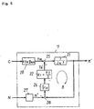
- Fig. 8 is a entire block diagram for explaining the operation of an example of the apparatus shown in Fig. 7.
- Fig. 9 is an entire block diagram for explaining the operation of another example of the apparatus shown in Fig. 7.
- Fig. 10 is a block diagram of a speed control apparatus for motors according to a third embodiment of this invention.
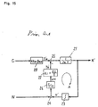
- Fig. 11 is an entire block diagram for explaining the operation of an example of the apparatus shown in Fig. 10.
- Fig. 12 is an entire block diagram for explaining the operation of another example of the apparatus shown in Fig. 10.
- Fig. 13 is a block diagram of a speed control apparatus for motors in the prior art.
- Fig. 14 is a waveform diagram showing a relation between an instantaneous rotating speed n and a mean rotating speed N of a motor.
- Fig. 15 is a block diagram of a speed estimating unit in the prior art.
- Fig. 1 is a block diagram of a speed control apparatus for motors according to a first embodiment of this invention.
- a motor 1 is driven by a driving current ia and generates a driving torque ⁇ m to be rotated and the rotation axis is applied with disturbance torque ⁇ d
- a frequency generator 2 generates a frequency signal proportional to a rotating speed of the motor 1
- a period detector 3 detects a period of the frequency signal fs to output a rotating speed signal N
- a drive circuit 4 supplies the motor 1 with a driving current ia in accordance with a control signal C
- a speed estimating unit 7 obtains a generated torque ⁇ m' of the motor 1 in response to the control signal C supplied to the drive circuit 4 and detects an instantaneous rotating speed signal n' from the generated torque ⁇ m' and the rotating speed signal N to be outputted to a comparator 5 which compares the instantaneous rotating speed signal ⁇ n' and a rotating speed command signal nr (constant value
- the rotating speed of the motor 1 is sampled by the period of the frequency signal fs of the period generator 2 and the detection result is held only for the period thereof.
- the detection result of rotating speed of the motor 1 does not show an instantaneous value of the rotating speed at the time point when sampling, but shows a mean value of the rotating speed for the period of the frequency signal fs, thus having a detection time delay.
- the estimated value of rotating speed can be obtained, as shown in the equation (3), by integrating the deviation between the generated torque ⁇ m' of the motor 1 generated in accordance with the control signal C and the estimated load torque ⁇ d' applied to the motor 1 divided by the rotor inertia Jn of the motor with respect to time.
- a conventional speed control apparatus estimates the load torque ⁇ d by simply proportionally integrating the deviation between the mean speed detection value N of the period detector 3 and the mean value N' of estimated speed n'.
- the speed detection delay is reduced by estimating the instantaneous speed n' from thus estimated load torque ⁇ d' and the generated torque ⁇ m' of the motor 1 in accordance with the control signal C.
- the comparator 5 and the controller 6 control the rotating speed of the motor 1 with the instantaneous rotating speed n' estimated by the speed estimating unit 7 in response to the speed command signal nr as the feedback signal.
- Fig. 2 is a block diagram of the speed estimating unit 7 shown in Fig. 1.
- the members having the same functions as those of the conventional speed estimating unit shown in Fig. 15 are denoted at the same reference numerals and the explanations thereof will be omitted for avoiding duplication.
- the speed estimating unit 7 shown in Fig. 2 and the conventional speed estimating units shown in Fig. 15 are different in that with the conventional unit shown in Fig. 15, the output of a sample & holder 26 is directly sent to a proportional integral compensator 22, but with the speed estimating unit 7 shown in Fig. 2, the output of the sample & holder 26 is through a predictor 27 to the proportional integrated compensator 22.
- the reference numeral 31 denotes the speed deviation ⁇ n (instantaneous value), which is supposed to be changed as shown in the diagram
- 32 is the mean rotating speed deviation ⁇ N, which is sampled by the frequency signal fs of the frequency generator 2 and obtained during the period T.
- the mean rotating speed deviation ⁇ N is, as seen in Fig. 3, changed in steps at time points t(i-1), t(i), t(i+1) & with the period T of the frequency signal fs, thus holding it constant during the period T
- 33 shown by the dotted line shows a rotating speed of the motor 1 estimated from the mean rotating speed deviation ⁇ N shown at 32, which has a detection time delay of about T compared with the rotating speed deviation ⁇ N of the motor as clearly seen in Fig. 3.
- Fig. 15 showing the conventional speed estimating unit, if structured such that the mean rotating speed deviation ⁇ N is sent through the sample & holder 22 to the proportional integral compensator 22 for processing, the control frequency band cannot be so much increased in order to stabilized the control system of a loop A shown in Fig. 15 due to the above-mentioned detection time delay.
- the speed estimating unit 7 shown in Fig. 2 operationally estimates the instantaneous rotating speed deviation ⁇ n of the motor from the mean rotating speed deviation ⁇ N and sends the estimated value to the proportional integral compensator 22 for processing, so that the control frequency band can be highly set independently of the detection time delay.
- Fig. 4 shows the equation (5) by means of the block diagram, showing a block diagram of the predictor 27 as a member of the speed estimating unit 7.
- 41 is a multiplier whose constant is 2
- 42 is a delay circuit to delay only one sampling period T (in this case, the period of the frequency signal fs of the frequency generator 2)
- 43 is a subtracter for subtracting the rotating speed deviation ⁇ n(i-1) obtained by the preceding operation of one sampling period T from the mean rotating speed deviation 2 ⁇ N(i) doubled through the multiplier 41.
- the operation results of the subtracter 43 shows the rotating speed deviation ⁇ n(i) obtained by the equation (5).
- the predictor 27 makes possible to obtain the instantaneous rotating speed deviation ⁇ n of the motor when sampling at the present time point from the mean rotating speed deviation ⁇ N when sampling at the present time point.
- Fig. 5 is a Bode diagram showing the transmission characteristics from the mean rotating speed deviation ⁇ N to the instantaneous rotating speed deviation ⁇ n of the block diagram of the predictor 27 at (a) of Fig. 4.
- the reference numeral 51 denotes the amplitude characteristic of the black diagram shown at (a) of Fig. 4, and 52 at (b) of Fig. 5 is the phase characteristic of the block diagram shown at (a) of Fig. 4.
- the abscissas of Fig. 5 are normalized based on the sampling frequency fs (equal to the frequency of a frequency signal outputted from the frequency generator 2) .
- the process of the predictor 27 shown in the block diagram of (a) of Fig. 4 characterizes the phase leading, but as seen from 51 at (a) of Fig. 5, the control system is unstable (the amplitude characteristic becomes infinite at frequency fs/2) and becomes unpractical.
- the Bode diagram shown at (b) of Fig. 4 is used instead of that shown at (b) Fig. 4. In this case, however, the coefficient ⁇ at (b) of Fig.
- ⁇ so as to be 0 ⁇ ⁇ ⁇ 1.
- the amplitude characteristic when the coefficient is ⁇ made 0.7 in the block diagram shown at (b) of Fig. 4 is shown at 53 at (a) of Fig. 5 and the phase characteristic thereof is shown at 54 at (b) of Fig. 5.
- ⁇ so as to be smaller than one, the control system of the predictor 27 can be stabilized and the phase leading characteristic can be obtained in the frequency range below fs/2.
- the frequency band of the loop A of speed estimating unit can be made larger than that in the prior art and the load torque disturbance applied to the motor can be estimated up to higher frequency levels, so that the speed estimating unit 7 makes it possible to estimate the estimated rotating speed n' accurately up to higher frequency band levels.
- the speed control apparatus for motors of this invention performs the speed control with the estimated rotating speed n' as the feedback signal, so that the speed change due to disturbance of load torque can be stably reduced up to higher frequency band levels.
- Fig. 6 is a black diagram showing another example of the speed estimating unit 7.
- the members having the same functions as those of the speed estimating unit 7 according to this invention shown in Fig. 2 are denoted at the same reference numerals and their explanations will be omitted or avoiding duplication.
- This example is different in structure from that shown in Fig. 2 in that in the case of the unit shown in Fig. 2, the integrator 23 is inserted into the loop A, but in the case of the unit shown in Fig. 7, as shown in Fig. 6, there does not use the integrator 23 and the estimated rotating speed n' as an output of the integrator 21 is directely to the comparator 24.
- the mean rotating speed N generated by the frequency generator 3 is sent through the predictor 27 to the comparator 24 to be applied with the subtraction therethrough and then, sent successively to the sample & holder 26 and the proportional integral compensator 22 for processing.
- n (i) 2 ⁇ N (i)- n (i-l)
- the instantaneous rotating speed n can be predicted from the mean rotating speed N by operation using the equation (7).
- the integrator 23 generating phase delay is not included into the loop B, and the constants K1 and K2 of the proportional integral compensator 22 can be set large compared with the speed estimating unit 7 shown in Fig. 2.
- the loop B shown in Fig. 6 can be further expanded in control frequency band compared with the loop A shown in Fig. 2.
- the frequency band of the loop B of the speed estimating unit 7 can be expanded and the load torque disturbance applied to the motor can be estimated up to higher frequency levels, so that the speed estimating unit 7 can estimate the estimated rotating speed n' accurately up to higher frequency levels.
- the example shown in Fig. 6 does not need such a integrator 23 that is required in Fig. 2, so that the speed estimating unit 7 can be made simple in structure.
- Fig. 7 is a block diagram of a speed control apparatus for motors according to a second embodiment of this invention.
- the members having the same functions as those in Fig. 1 will be denoted at the same reference numerals and their explanations will be omitted for avoiding duplication.
- the second embodiment shown in Fig. 7 is different in structure from the first embodiment shown in Fig. 1 in that in the case of the first embodiment, the output of the speed estimating unit 7 is only the estimated rotating speed n' and supplies it to the comparator 5, however, in the case of the second embodiment shown in Fig. 7, the estimated load torque ⁇ d' obtained by operation through a speed estimating unit 8 is used for performing feed forward compensation with the control signal C outputted from the controller 6.
- the reference numeral 9 denotes a corrector which receives the control signal C from the controller 6 and the estimated load torque ⁇ d' from the speed estimating unit 8, operates the compensation and outputs a corrected signal d to the drive circuit 4.
- the estimated load torque ⁇ d' is sent to the corrector 9 which comprises a multiplier 91 for multiplying a constant 1/(ktn ⁇ gmn) to be outputted and an adder 92 for adding the operation result of the multiplier 91 to the control signal C form the controller 6 to be outputted to the drive circuit 4 (transform constant is gm) as the corrected signal.
- the estimated load torque ⁇ d' outputted from the speed estimating unit 8 is equal to the load torque ⁇ d applied to the motor 1 in the frequency range not exceeding the control frequency band of the loop A, so that the actual load torque ⁇ d and the estimated load torque ⁇ d' are canceled each other through the adder 12 as a component of the block diagram 1 of the motor.
- the motor 1 behaves as if the disturbance of the load torque ⁇ d is not applied to a transfer function 13 (its coefficient is 1/Js). Accordingly, the motor 1 can be driven at a high rotation accuracy without receiving any influence of the load torque disturbance on a practical basis.
- the speed control apparatus performs speed control using the estimated rotating speed n' obtained by the speed estimating unit 8, so that the speed change due to the load torque disturbance can be stably reduced up to higher frequency band levels.
- the load torque ⁇ d applied to the motor 1 can be canceled, so that the speed change due to load torque disturbance of the motor can be further reduced.
- the speed estimating unit 8 is structured based on that shown in Fig. 2 as clearly from the block diagram shown in Fig. 8.
- Fig. 9 is a block diagram showing another example of the speed estimating unit 8 of the second embodiment based on the structure shown in Fig. 6.
- the members having the same functions as those shown in Figs. 6 and 8 are denoted at the same reference numerals and their explanations are omitted for avoiding duplication.
- the control frequency band of the loop B of the speed estimating unit 8 can be expanded, so that the same effects as with the example shown in Fig. 8 can be obtained.
- the integrator 23 such as to be required in the case of the example shown in Fig. 8, so that the speed estimating unit can be made simpler in structure.
- Fig. 10 is a block diagram of a speed control apparatus for motors according to a third embodiment of this invention.
- the members having the same functions as those shown in Figs. 1 and 7 are denoted at the same reference numerals and their explanations are omitted for avoiding duplication.
- the unit shown in Fig. 10 is different from that shown in Fig. 7 in that in the case of Fig. 7, the speed estimating unit 8 receives the corrected signal d outputted from the corrector 9 as its input, but in the case of Fig. 10, the speed estimating unit 10 receives the control signal c outputted from the speed controller 6 as its input.
- the estimated load torque ⁇ d' estimated by the speed estimating unit 10 is sent to the corrector 9. After correcting through the corrector 9, the corrected signal d thus obtained is sent to the drive circuit 4.
- Fig. 11 is an entire block diagram for explaining the speed control apparatus for motors shown in Fig. 10.
- the members having the same functions as those shown in Fig. 8 are denoted at the same reference numerals and their explanations are omitted for avoiding duplication.
- FIG. 11 10 is a block diagram of the speed estimating unit according to the third embodiment, in which the subtracter 25 is not needed.
- the speed estimating unit 8 according to the second embodiment shown in Fig. 8 needs the subtracter 25 for subtracting the estimated load torque ⁇ d' from the estimated generated torque ⁇ m' obtained by multiplying the corrected signal d by the constant (Ktn ⁇ gmn) of the multiplier 28 thereby to obtain the signal ⁇ ' which is sent to the integrator 21.
- the structure of the speed estimating unit 10 shown in Fig. 11 maybe obtained. That is, the control signal c of the controller 6 is sent to the multiplier 28 to be multiplied by the constant (Ktn ⁇ gmn) thereby to obtain the estimated acceleration torque ⁇ '.
- the estimated acceleration torque ⁇ ' is sent to the integrator 21 to be multiplied by the constant 1/(Jn s) thereby to obtain -the estimated rotating speed n'.
- the estimated load torque ⁇ d' is sent to the corrector 9 and similar to the case of Fig. 8, the estimated load torque ⁇ d' outputted from the speed estimating unit 10 is equal to the load torque ⁇ d applied to the motor 1, so that the actual load torque ⁇ d and the estimated load torque ⁇ d' can be canceled each other through the adder 12.
- the motor 1 can be driven at a high rotation accuracy.
- the estimated load torque ⁇ d' applied to the motor and the estimated rotating speed n' can be estimated up to higher frequency band levels with simpler structure than that shown in Fig. 8.
- the speed control apparatus for motors makes possible to stably reduce the speed change due to the disturbance of load torque up to higher frequency band levels by speed-controlling using the estimated rotating speed n' obtained by the speed estimating unit 10 and to cancel the load torque ⁇ d applied to the motor 1 by feedforward-compensating the estimated load torque ⁇ d' by the corrector 9, so that the speed change due to the load torque disturbance of the motor can be further reduced.
- the structure of the speed estimating unit 10 is based on that shown in Fig. 2.
- Fig. 12 is a block diagram showing another example of the speed estimating unit 10 according to the third embodiment, the structure of which is based on the structure of the unit shown in Fig. 6.
- the members having the same functions as those shown in Figs. 6 and 11 are denoted at the same reference numerals and their explanations are omitted for avoiding duplication.
- the speed estimating unit receives the control signal from the controller as its input signal, however, it is needless to say that even if the driving current outputted from the drive circuit is used instead of the control signal, the same effects can be obtained.
- integrator 21 and the proportional integral compensator 22 were explained above so as to be made of analog filters, but not limited thereto, they may be made of digital filters. Further in addition, each of the members forming the control apparatus may be realized by softwares by micro-computers.
- the controlled output signal of each member in the above embodiments was explained as a continuous signal, but not limited thereto, it may be outputted as a discrete signal, and if the output sampling period is made sufficiently shorter than the period of an output frequency signal of the frequency generator, the same effects as those obtained in the continuous signal case can be obtained.
Landscapes
- Engineering & Computer Science (AREA)
- Power Engineering (AREA)
- Control Of Electric Motors In General (AREA)
- Feedback Control In General (AREA)
Applications Claiming Priority (3)
| Application Number | Priority Date | Filing Date | Title |
|---|---|---|---|
| JP26020494A JP3203989B2 (ja) | 1994-10-25 | 1994-10-25 | モータの速度制御装置 |
| JP260204/94 | 1994-10-25 | ||
| US08/548,047 US5737483A (en) | 1994-10-25 | 1995-10-25 | Motor speed control apparatus for motors |
Publications (2)
| Publication Number | Publication Date |
|---|---|
| EP0709952A1 true EP0709952A1 (de) | 1996-05-01 |
| EP0709952B1 EP0709952B1 (de) | 1999-03-31 |
Family
ID=26544495
Family Applications (1)
| Application Number | Title | Priority Date | Filing Date |
|---|---|---|---|
| EP95307525A Expired - Lifetime EP0709952B1 (de) | 1994-10-25 | 1995-10-24 | Apparat zur Steuerung der Drehzahl eines Motors |
Country Status (3)
| Country | Link |
|---|---|
| US (1) | US5737483A (de) |
| EP (1) | EP0709952B1 (de) |
| JP (1) | JP3203989B2 (de) |
Cited By (1)
| Publication number | Priority date | Publication date | Assignee | Title |
|---|---|---|---|---|
| CN102346441A (zh) * | 2010-07-30 | 2012-02-08 | 上海微电子装备有限公司 | 一种编码器信号模拟装置及方法 |
Families Citing this family (14)
| Publication number | Priority date | Publication date | Assignee | Title |
|---|---|---|---|---|
| JP3291224B2 (ja) * | 1997-06-30 | 2002-06-10 | オークマ株式会社 | 速度制御装置 |
| JP3900219B2 (ja) * | 1997-10-24 | 2007-04-04 | 株式会社安川電機 | 電動機速度制御装置および同装置のゲイン設定方法 |
| US6075332A (en) * | 1998-05-14 | 2000-06-13 | Mccann; Roy A. | Predictive conductive angle motor control system for brake-by-wire application |
| US7177106B2 (en) * | 2001-02-26 | 2007-02-13 | Matsushita Electric Industrial Co., Ltd. | Disk storage apparatus |
| US7245103B2 (en) * | 2003-03-03 | 2007-07-17 | Lexmark International, Inc. | Motor speed and position control |
| US6889013B2 (en) * | 2003-06-10 | 2005-05-03 | Lexmark International, Inc. | Optimizing a printing motor under varying torque loads |
| US7205738B2 (en) * | 2004-03-24 | 2007-04-17 | Lexmark International, Inc. | Method and apparatus for time-based dc motor commutation |
| US7502703B2 (en) * | 2007-07-09 | 2009-03-10 | Xerox Corporation | Calibration of the fundamental and harmonic once-around velocity variations of encoded wheels |
| KR101220915B1 (ko) * | 2011-11-04 | 2013-02-14 | 주식회사 오토파워 | 활성화 함수와 토크 보상기를 이용한 속도 리플 억제 방법 |
| CN103286727B (zh) * | 2012-03-02 | 2015-06-10 | 南京德朔实业有限公司 | 可调节扭力的冲击扳手 |
| US9523947B2 (en) | 2012-09-26 | 2016-12-20 | Lexmark International, Inc. | Time-based commutation method and system for controlling a fuser assembly |
| US8836747B2 (en) | 2012-10-02 | 2014-09-16 | Lexmark International, Inc. | Motor control system and method for a laser scanning unit of an imaging apparatus |
| JP7405731B2 (ja) * | 2020-11-26 | 2023-12-26 | 株式会社モリタ製作所 | 歯科用治療装置、およびその制御方法 |
| CN117977885B (zh) * | 2024-04-01 | 2024-06-14 | 佛山市津上医疗科技有限公司 | 一种根管马达检测结构及方法 |
Citations (5)
| Publication number | Priority date | Publication date | Assignee | Title |
|---|---|---|---|---|
| JPS6392283A (ja) * | 1986-10-07 | 1988-04-22 | Matsushita Electric Ind Co Ltd | モ−タの速度制御装置 |
| US4745563A (en) * | 1984-02-17 | 1988-05-17 | Yaskawa Electric Mfg. Co., Ltd. | Method of detecting the speed of a motor |
| WO1992009016A1 (en) * | 1990-11-09 | 1992-05-29 | Matsushita Electric Industrial Co., Ltd. | Speed control device and predicting machine |
| JPH05197978A (ja) * | 1992-01-21 | 1993-08-06 | Mitsubishi Electric Corp | 外部記憶装置 |
| EP0599190A2 (de) * | 1992-11-24 | 1994-06-01 | Matsushita Electric Industrial Co., Ltd. | Einrichtung zur Drehzahlregelung von Motoren |
Family Cites Families (2)
| Publication number | Priority date | Publication date | Assignee | Title |
|---|---|---|---|---|
| TW221535B (de) * | 1991-05-20 | 1994-03-01 | Meidensha Electric Mfg Co Ltd | |
| US5471880A (en) * | 1994-04-28 | 1995-12-05 | Electric Power Research Institute | Method and apparatus for isolating and identifying periodic Doppler signals in a turbine |
-
1994
- 1994-10-25 JP JP26020494A patent/JP3203989B2/ja not_active Expired - Fee Related
-
1995
- 1995-10-24 EP EP95307525A patent/EP0709952B1/de not_active Expired - Lifetime
- 1995-10-25 US US08/548,047 patent/US5737483A/en not_active Expired - Fee Related
Patent Citations (5)
| Publication number | Priority date | Publication date | Assignee | Title |
|---|---|---|---|---|
| US4745563A (en) * | 1984-02-17 | 1988-05-17 | Yaskawa Electric Mfg. Co., Ltd. | Method of detecting the speed of a motor |
| JPS6392283A (ja) * | 1986-10-07 | 1988-04-22 | Matsushita Electric Ind Co Ltd | モ−タの速度制御装置 |
| WO1992009016A1 (en) * | 1990-11-09 | 1992-05-29 | Matsushita Electric Industrial Co., Ltd. | Speed control device and predicting machine |
| JPH05197978A (ja) * | 1992-01-21 | 1993-08-06 | Mitsubishi Electric Corp | 外部記憶装置 |
| EP0599190A2 (de) * | 1992-11-24 | 1994-06-01 | Matsushita Electric Industrial Co., Ltd. | Einrichtung zur Drehzahlregelung von Motoren |
Non-Patent Citations (2)
| Title |
|---|
| PATENT ABSTRACTS OF JAPAN vol. 012, no. 328 (E - 654) 6 September 1988 (1988-09-06) * |
| PATENT ABSTRACTS OF JAPAN vol. 017, no. 624 (P - 1646) 17 November 1993 (1993-11-17) * |
Cited By (2)
| Publication number | Priority date | Publication date | Assignee | Title |
|---|---|---|---|---|
| CN102346441A (zh) * | 2010-07-30 | 2012-02-08 | 上海微电子装备有限公司 | 一种编码器信号模拟装置及方法 |
| CN102346441B (zh) * | 2010-07-30 | 2013-05-22 | 上海微电子装备有限公司 | 一种编码器信号模拟装置及方法 |
Also Published As
| Publication number | Publication date |
|---|---|
| US5737483A (en) | 1998-04-07 |
| JP3203989B2 (ja) | 2001-09-04 |
| JPH08126372A (ja) | 1996-05-17 |
| EP0709952B1 (de) | 1999-03-31 |
Similar Documents
| Publication | Publication Date | Title |
|---|---|---|
| EP0709952A1 (de) | Apparat zur Steuerung der Drehzahl eines Motors | |
| US5773938A (en) | Apparatus for controlling speed of a rotary motor | |
| US5666034A (en) | Method for controlling velocity of a rotary motor and an apparatus therefor | |
| EP0805383B1 (de) | Schaltung zur Regelung der Drehzahl eines Rotationsmotors | |
| KR0133354B1 (ko) | 모터제어장치 | |
| US5710500A (en) | Motor speed control apparatus using phase-advance based estimated disturbance signal | |
| US5481641A (en) | Motor control apparatus | |
| JP2566033B2 (ja) | 外乱抑圧制御システム | |
| JPH03155383A (ja) | モータ制御装置 | |
| JP3337826B2 (ja) | オープンループ振動抑制方法 | |
| JP2658976B2 (ja) | モータの速度制御方式 | |
| JP3348240B2 (ja) | デジタルフィルタと、サーボモータ制御装置 | |
| JPH06165550A (ja) | 電動機制御方法および電動機制御装置 | |
| KR0124655B1 (ko) | 모터 제어 장치 | |
| JPH09163780A (ja) | モータ速度制御装置 | |
| JP2914726B2 (ja) | 帰還型ディジタルくし形フィルタ | |
| JP2846504B2 (ja) | モータ制御装置 | |
| KR0131584B1 (ko) | 개선된 반복 학습 제어 방식을 이용한 모터 속도 제어 장치 및 방법 | |
| JPH07177777A (ja) | モータ制御装置 | |
| JPH06225567A (ja) | モータ制御装置 | |
| JP2754807B2 (ja) | 回転体の制御装置 | |
| JP3227838B2 (ja) | モータ制御装置 | |
| JPH10174472A (ja) | モータの速度制御装置 | |
| JPH0352583A (ja) | ドラムモータの制御装置 | |
| JPH06233573A (ja) | モータ制御装置 |
Legal Events
| Date | Code | Title | Description |
|---|---|---|---|
| PUAI | Public reference made under article 153(3) epc to a published international application that has entered the european phase |
Free format text: ORIGINAL CODE: 0009012 |
|
| AK | Designated contracting states |
Kind code of ref document: A1 Designated state(s): DE FR GB NL |
|
| 17P | Request for examination filed |
Effective date: 19961025 |
|
| 17Q | First examination report despatched |
Effective date: 19970604 |
|
| GRAG | Despatch of communication of intention to grant |
Free format text: ORIGINAL CODE: EPIDOS AGRA |
|
| GRAG | Despatch of communication of intention to grant |
Free format text: ORIGINAL CODE: EPIDOS AGRA |
|
| GRAH | Despatch of communication of intention to grant a patent |
Free format text: ORIGINAL CODE: EPIDOS IGRA |
|
| GRAH | Despatch of communication of intention to grant a patent |
Free format text: ORIGINAL CODE: EPIDOS IGRA |
|
| GRAA | (expected) grant |
Free format text: ORIGINAL CODE: 0009210 |
|
| AK | Designated contracting states |
Kind code of ref document: B1 Designated state(s): DE FR GB NL |
|
| PG25 | Lapsed in a contracting state [announced via postgrant information from national office to epo] |
Ref country code: NL Free format text: LAPSE BECAUSE OF FAILURE TO SUBMIT A TRANSLATION OF THE DESCRIPTION OR TO PAY THE FEE WITHIN THE PRESCRIBED TIME-LIMIT Effective date: 19990331 |
|
| REF | Corresponds to: |
Ref document number: 69508698 Country of ref document: DE Date of ref document: 19990506 |
|
| ET | Fr: translation filed | ||
| NLV1 | Nl: lapsed or annulled due to failure to fulfill the requirements of art. 29p and 29m of the patents act | ||
| PLBE | No opposition filed within time limit |
Free format text: ORIGINAL CODE: 0009261 |
|
| STAA | Information on the status of an ep patent application or granted ep patent |
Free format text: STATUS: NO OPPOSITION FILED WITHIN TIME LIMIT |
|
| 26N | No opposition filed | ||
| REG | Reference to a national code |
Ref country code: GB Ref legal event code: IF02 |
|
| PGFP | Annual fee paid to national office [announced via postgrant information from national office to epo] |
Ref country code: FR Payment date: 20051010 Year of fee payment: 11 |
|
| PGFP | Annual fee paid to national office [announced via postgrant information from national office to epo] |
Ref country code: GB Payment date: 20051019 Year of fee payment: 11 |
|
| PGFP | Annual fee paid to national office [announced via postgrant information from national office to epo] |
Ref country code: DE Payment date: 20051020 Year of fee payment: 11 |
|
| PG25 | Lapsed in a contracting state [announced via postgrant information from national office to epo] |
Ref country code: DE Free format text: LAPSE BECAUSE OF NON-PAYMENT OF DUE FEES Effective date: 20070501 |
|
| GBPC | Gb: european patent ceased through non-payment of renewal fee |
Effective date: 20061024 |
|
| REG | Reference to a national code |
Ref country code: FR Ref legal event code: ST Effective date: 20070629 |
|
| PG25 | Lapsed in a contracting state [announced via postgrant information from national office to epo] |
Ref country code: GB Free format text: LAPSE BECAUSE OF NON-PAYMENT OF DUE FEES Effective date: 20061024 |
|
| PG25 | Lapsed in a contracting state [announced via postgrant information from national office to epo] |
Ref country code: FR Free format text: LAPSE BECAUSE OF NON-PAYMENT OF DUE FEES Effective date: 20061031 |