EP0709979A2 - Dispositif et méthode pour la correction d'erreurs d'un signal de données en fonction des violations du code de transmission et de parité - Google Patents
Dispositif et méthode pour la correction d'erreurs d'un signal de données en fonction des violations du code de transmission et de parité Download PDFInfo
- Publication number
- EP0709979A2 EP0709979A2 EP95114361A EP95114361A EP0709979A2 EP 0709979 A2 EP0709979 A2 EP 0709979A2 EP 95114361 A EP95114361 A EP 95114361A EP 95114361 A EP95114361 A EP 95114361A EP 0709979 A2 EP0709979 A2 EP 0709979A2
- Authority
- EP
- European Patent Office
- Prior art keywords
- parity
- bytes
- transmitted
- frame
- balance
- Prior art date
- Legal status (The legal status is an assumption and is not a legal conclusion. Google has not performed a legal analysis and makes no representation as to the accuracy of the status listed.)
- Withdrawn
Links
Images


Classifications
-
- H—ELECTRICITY
- H04—ELECTRIC COMMUNICATION TECHNIQUE
- H04L—TRANSMISSION OF DIGITAL INFORMATION, e.g. TELEGRAPHIC COMMUNICATION
- H04L1/00—Arrangements for detecting or preventing errors in the information received
- H04L1/004—Arrangements for detecting or preventing errors in the information received by using forward error control
- H04L1/0056—Systems characterized by the type of code used
- H04L1/0057—Block codes
-
- G—PHYSICS
- G06—COMPUTING OR CALCULATING; COUNTING
- G06F—ELECTRIC DIGITAL DATA PROCESSING
- G06F11/00—Error detection; Error correction; Monitoring
- G06F11/07—Responding to the occurrence of a fault, e.g. fault tolerance
- G06F11/08—Error detection or correction by redundancy in data representation, e.g. by using checking codes
- G06F11/10—Adding special bits or symbols to the coded information, e.g. parity check, casting out 9's or 11's
-
- H—ELECTRICITY
- H03—ELECTRONIC CIRCUITRY
- H03M—CODING; DECODING; CODE CONVERSION IN GENERAL
- H03M13/00—Coding, decoding or code conversion, for error detection or error correction; Coding theory basic assumptions; Coding bounds; Error probability evaluation methods; Channel models; Simulation or testing of codes
- H03M13/03—Error detection or forward error correction by redundancy in data representation, i.e. code words containing more digits than the source words
- H03M13/05—Error detection or forward error correction by redundancy in data representation, i.e. code words containing more digits than the source words using block codes, i.e. a predetermined number of check bits joined to a predetermined number of information bits
- H03M13/09—Error detection only, e.g. using cyclic redundancy check [CRC] codes or single parity bit
- H03M13/095—Error detection codes other than CRC and single parity bit codes
-
- H—ELECTRICITY
- H03—ELECTRONIC CIRCUITRY
- H03M—CODING; DECODING; CODE CONVERSION IN GENERAL
- H03M13/00—Coding, decoding or code conversion, for error detection or error correction; Coding theory basic assumptions; Coding bounds; Error probability evaluation methods; Channel models; Simulation or testing of codes
- H03M13/03—Error detection or forward error correction by redundancy in data representation, i.e. code words containing more digits than the source words
- H03M13/05—Error detection or forward error correction by redundancy in data representation, i.e. code words containing more digits than the source words using block codes, i.e. a predetermined number of check bits joined to a predetermined number of information bits
- H03M13/09—Error detection only, e.g. using cyclic redundancy check [CRC] codes or single parity bit
- H03M13/098—Error detection only, e.g. using cyclic redundancy check [CRC] codes or single parity bit using single parity bit
-
- H—ELECTRICITY
- H04—ELECTRIC COMMUNICATION TECHNIQUE
- H04L—TRANSMISSION OF DIGITAL INFORMATION, e.g. TELEGRAPHIC COMMUNICATION
- H04L1/00—Arrangements for detecting or preventing errors in the information received
- H04L1/004—Arrangements for detecting or preventing errors in the information received by using forward error control
-
- H—ELECTRICITY
- H04—ELECTRIC COMMUNICATION TECHNIQUE
- H04L—TRANSMISSION OF DIGITAL INFORMATION, e.g. TELEGRAPHIC COMMUNICATION
- H04L25/00—Baseband systems
- H04L25/38—Synchronous or start-stop systems, e.g. for Baudot code
- H04L25/40—Transmitting circuits; Receiving circuits
- H04L25/49—Transmitting circuits; Receiving circuits using code conversion at the transmitter; using predistortion; using insertion of idle bits for obtaining a desired frequency spectrum; using three or more amplitude levels ; Baseband coding techniques specific to data transmission systems
- H04L25/4906—Transmitting circuits; Receiving circuits using code conversion at the transmitter; using predistortion; using insertion of idle bits for obtaining a desired frequency spectrum; using three or more amplitude levels ; Baseband coding techniques specific to data transmission systems using binary codes
- H04L25/4908—Transmitting circuits; Receiving circuits using code conversion at the transmitter; using predistortion; using insertion of idle bits for obtaining a desired frequency spectrum; using three or more amplitude levels ; Baseband coding techniques specific to data transmission systems using binary codes using mBnB codes
Definitions
- the present invention is directed to an apparatus and method for correcting errors in a transmission of digital data.
- the primary purpose of transmission codes is to transform the frequency spectrum of a serial data stream so that clocking can be recovered readily and AC coupling is possible.
- the code must also provide special characters outside the data alphabet for functions such as character synchronization, frame delimiters and perhaps for abort, reset, idle, diagnostics, etc.
- Codes are also used, often in combination with signal waveform shaping, to adapt the signal spectrum more closely to specific channel requirements. In most cases, a reduction in bandwidth by constraints on both the high and the low frequency components is desirable to reduce distortion in the transmission media, especially electromagnetic cables, or in the band limited receiver, and to reduce the effects of extrinsic and intrinsic noise.
- Another aspect of codes is their interaction with noise and errors in the line digits. The redundancy associated with line codes can be used to supplement other error detection mechanisms or to monitor the quality of the channel with a minimal amount of circuitry.
- Such codes generally exhibit the undesirable feature of enlarging error bursts in the decoded data, making error detection by a cyclic redundancy check more difficult.
- a good transmission code should minimize these effects.
- the task force considered the outlines of a specific FEC proposal.
- the proposal included a table lookup 8B/10B code and an 8 bit shortened Hamming code applied to the coded bits for every 8 information bytes.
- the FEC bits are Manchester coded.
- One pair of such coded bits is inserted between the 8B/10B coded bytes.
- the data transfer rate is reduced from 0.8 to 0.667. A single error in 8 data bytes can always be corrected.
- each byte and its associated horizontal parity are transmitted and the byte 52 corresponding to the vertical parities for each of the bit locations is transmitted with the frame.
- the receiving machine For each transmitted byte, the receiving machine recomputes a horizontal parity for each transmitted byte and recomputes a vertical parity for the transmitted frame. The recomputed horizontal parity is compared to the transmitted horizontal parity, and the recomputed vertical parity is compared to the transmitted vertical parity.
- the raw binary data is generally not transmitted but is first converted into coded data having bytes with a larger number of bits than contained in the raw data bytes. Coding is used for a number of reasons.
- a delimiter is needed to define word boundaries and frame boundaries.
- a delimiter is needed so that when data is transmitted, the receiver can determine where the frame of data which is being sent begins.
- the delimiter is commonly referred to as a comma.
- it is desirable when transmitting data to have run lengths of consecutive ones or of consecutive zeros which are short in order to provide a steady stream of transitions as timing references to the clock recovery circuit of the receiver. Coded data is used to limit the run length to less than some predetermined value.
- coded bytes have more bits than contained in the byte of raw data, it is undesirable to use classical horizontal and vertical parity with coded data since the horizontal parity for the coded data is likely to need more than one bit location in the coded byte. For a frame containing a large number of bytes, the horizontal parity would add a substantially large amount of additional bytes, thereby resulting in a significant impact on the number of bit locations which are carrying useful information.
- a limited set e.g. 8
- Another broad aspect of the present invention is a method and apparatus for transmitting from a first electronic device a frame of code constrained bytes of bits which contains a first and second parity which are used to correct errors in the frame when the frame is received by a second electronic device.
- the frame contains a plurality of coded constrained bytes.
- the second electronic device determines a first parity for the bytes of the frame; determines a balance for each of the code constrained bytes; groups the bytes into words, each word has a word balance formed from the balance of each of the bytes in the word.
- Another broad aspect of the present invention is a method and apparatus for correcting errors in coded bytes of binary data transmitted from a first electronic device to a second device by receiving from said first electronic device a transmitted frame of bits and a first transmitted parity and a second transmitted parity; the transmitted frame contains a plurality of coded constrained bytes of bits; determining a first redetermined parity for the bytes of the transmitted frame; determining a balance bit for each of the plurality of bytes; grouping the bytes into words, each word has a balance bit formed from the balance of each of the bytes in the word; determining a second redetermined parity from the byte and word balance bits; said second electronic device compares the transmitted first parity to the redetermined first parity to determine a bit location of an error in the bytes; the second electronic device compares the transmitted second parity to the redetermined second parity to determine which of the bytes from a sequence of 16 ending with the byte indicating a transmission code violation contains said error; and changing said bit location in said
- An invention described herein is directed to a method to correct a single erroneous byte in a frame.
- the fundamental principle is using a rectangular arrangement of horizontal and vertical parity bits, where the horizontal parity locates the error and the vertical parity is used to correct it.
- the distinctive feature is that the functional equivalent of the horizontal parity is provided by a small set of parity bits derived from the byte disparities of the Fibre Channel Standard (FCS) transmission code combined with error detection by the code.
- FCS Fibre Channel Standard
- the implementation of this error correction scheme can be made transparent to the existing FCS link level hardware and to the FCS transmission protocol. There is no reduction in throughput, but there is added delay equal to the length of a frame.
- Figure 2 shows a modified horizontal and vertical parity technique according to the present invention.
- Table I is a more specific example of the technique schematically shown in Figure 2.
- Figure 2 shows a frame 100 of raw data. Sixteen bytes are shown from frame 100 which can have any number of bytes which is indicated by the series of dots 101.
- the bytes of the example of raw data in Fig. 2 have 8 bits, however, a byte can have any number of bits.
- the raw data is segmented into bytes, 16 of the bytes are labelled from 0-15. Each byte has 8 bits labelled 0-7.
- the X's correspond to bits of data which typically have a 1 or 0 value. According to the present invention, each raw data byte is transformed into a coded byte.
- a vertical parity 258 is determined for the raw data of the entire block 100.
- bit location 0 of the raw data has a corresponding vertical parity bit 110.
- Vertical parity bit 110 has a value of 1 or 0 depending upon the total number of 1's or 0's in the 0 bit location over the entire frame of raw data.
- Each coded byte has an initial disparity and a final disparity. The changes in disparity over each byte of the code is constrained to certain values. The initial disparity for each coded byte is the same as the final disparity of the preceding coded byte.
- the permitted disparity variation over a coded byte is determined by the selection of the coding. Hereinbelow, a code is described and the permitted disparity variation over each coded byte.
- Each coded byte has a balance BB.
- Bytes B0, B1, B2, and B3 have balance 212, 214, 216 and 218, respectively. If there are an equal number of 1's and 0's in a coded byte, the balance BB is 1, and if there are an unequal number of 1's and 0's in a coded byte, the balance BB is 0.
- Another balance corresponds to each word. For example, balance bits BB 212, 214, 216 and 218 together form a balance 220 corresponding to word 102. As shown in Figure 2, each one of the words 102, 104, 106 and 108 has a word balance 220, 238, 240 and 242, respectively, associated therewith.
- Each one of the word balances for example, balance 220 has a balance bit QB.
- the QB bits corresponding to balance byte 220, 238, 240 and 242 are 222, 232, 334 and 236, respectively.
- a balance vertical parity is determined from the two groups of balance bits BB and QB.
- the 0 bit location of the balance parity 254 is the parity of the BB0 bits, that is, parity 224 is the parity of bits 212, 226, 228, 230,...
- balance parity bits 248, 250 and 252 are the parities of the BB bits in bit location BB1, BB2, and BB3, respectively.
- the balance bits QB 222, 232, 234 and 236 are the balances, respectively, of word 220, 238, 240 and 242.
- Bit 240 corresponding to bit location QB4 is the parity of all the bits which are in the bit location QB4.
- balance parity bits 242, 244 and 246 are the parities of the balance bits in bit location QB5, QB6 and QB7, respectively.
- the balance parity 254 which is an 8-bit word is coded as a 10-bit byte 260.
- Vertical parity 258 which is an 8-bit byte is coded to a 10-bit byte 256.
- the machine which is transmitting the data transmits frame 100 including the coded vertical parity byte 256 and the coded balance parity byte 260.
- the receiving machine receives the coded bytes corresponding to frame 100 and generates a recomputed vertical parity corresponding to vertical parity 258 and generates a recomputed balance parity corresponding to balance parity 254.
- the receiving computer first looks at the coded bytes to determine if any of the bytes are an invalid arrangement of 1's and 0's. For the coded data, only certain arrangements of 1's and 0's are valid coded bytes. Others are not part of the code and, therefore, are invalid. If an invalid coded byte is found, it is known that an error is contained within that byte.
- an invalid coded byte If an invalid coded byte is found, it is corrected by looking at the recomputed vertical parity as compared to the transmitted vertical parity to identify which bit locations in the coded byte are in error. The value of the coded bits which are in error is then changed from a 1 to a 0 or vice versa.
- the disparity of each coded byte is checked to determine if there is a disparity violation.
- the variation in the disparity from the initial disparity to the final disparity of each valid coded byte is constrained within the code to be within a certain range, for example, the change in disparity over a valid coded byte could be limited to zero and plus or minus 2 as is the case for the FCS code.
- the polarity of coded bytes with non-zero disparity must alternate as described in detail hereinbelow to avoid a disparity violation. If there are no disparity violations in the disparities of each of the coded bytes within the transmitted frame, no errors are detected and nothing is done.
- the Fibre Channel Standard transmission code it has been calculated that statistically an error is with high probability within 16 bytes preceding the identified disparity violation for the case of random data.
- the probability that the error is more than 16 bytes preceding the disparity violation is about 2 X 10 .
- the balance parities identify the location of the byte having the error and the vertical parity identifies the location of the particular bits having errors.
- the procedure described above using a vertical parity and a new balance parity, according to the present invention is used with codes which do not contain local parity. Therefore, the procedure described above supplements codes which do not have local parity.
- does not have local parity and, therefore, the ability to identify errors is supplemented by the procedure described above according to the present invention.
- Balance Bits BB and BQ are defined for each coded byte and 4-byte word, respectively, with a value of one for balanced blocks and zero otherwise.
- Sets of 4 BB and 4 BQ bits are each arranged diagonally in separate quadruplets for successive groups of 4 bytes and 4 words, respectively.
- a parity bit is derived for each of the diagonal bit positions of all the BB and the BQ sets of a frame. Only these 8 parity bits BPAR are transmitted after the end of the frame.
- the FCS code by itself locates all single byte errors to a range of 16 bytes except one error in 5x10 . errors.
- Violations in the received BPAR bits are used to trace an error more precisely to a specific byte of the 16 byte group identified by the code.
- a set VPAR of 8 vertical parity bits derived from the uncoded data, and the 8 BPAR bits are coded and packed into the first Idle word following the End of Frame. After identification of a faulty byte at the receiver, the VPAR bits are used to correct it.
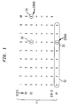
- the basic correction scheme proposed according to the present invention is based on ordering of data and parity bits, as shown in Figure 1, in a rectangular or matrix arrangement.
- a frame is partitioned into small segments, preferably bytes or words.
- a parity or other means of error detection is attached to each of the segments, and together they form a matrix line. Successive segments are placed on the following lines.
- This first set of parity bits is called the horizontal parity.
- the vertical parity consists of a parity bit for each data bit column. It is used to identify and correct the erroneous bit or bits in the segment which was tagged as erroneous by the horizontal parity.
- a necessary assumption is that, apart from short error bursts, the link error events occur randomly at a low enough rate so most of the time there is just a single error event within a frame. If this assumption does not hold, the frame length must be reduced, or a vertical parity must be inserted into the frame at fixed intervals. Another assumption is that most errors are confined to a single matrix line. The systems and methods shown described herein can be adapted to handle errors crossing line boundaries at the cost of increased complexity. It is a further requirement to have correct recognition of the start and the end of the frame in the presence of errors. A cyclic redundancy check computed over the frame ultimately determines the validity of the corrected or uncorrected frame.
- Retransmission facilities are preferably still available for the case where error correction fails: failure of the horizontal parity to detect certain multiple errors, an error burst longer than the vertical parity, lost byte synchronization, multiple error bursts, false start and end of frame detection, truncated or missing frames, etc.
- the horizontal parity is an explicit bit for each matrix line.
- the horizontal parity is instead supplied by the combination of a transmission code and a few parity bits at the end of the frame, computed on features of the code which are guaranteed to change for an odd number of errors.
- Transmission codes are subject to several constraints to enhance reliable low cost transmission. Additional constraints can be built into a code, so any odd number of errors in a byte or word generates an invalid word. Such a property of the code is referred to as 'local parity' [ Martin, 1985]. For general applications, such codes are less desirable, because the added constraint makes it necessary to degrade some transmission parameters, and to accept a more complex and higher cost implementation.
- Other 8B/10B codes, including the FCS Standard code most times also indicate immediately an invalid byte when an error has occurred. However, a substantial ratio of errors generates only a disparity violation farther down the bit stream, away from the byte where the error occurred, and so the byte which contains the error(s) cannot directly be identified.
- a virtual bit is attributed to each coded byte.
- a BB bit has a value of one for balanced vectors, and zero otherwise.
- the BB bit is not transmitted, it is just used to compute a set of parity bits as described below. If binary byte numbers are assigned as address to all bytes of a frame in ascending order, then BB0 is the balance bit of any byte with a low order binary address 00; BB1, BB2, and BB3 cover the binary byte address 01, 10, and 11, respectively.
- BB0 is the balance bit of the first byte of a word, and BB3 of the last byte of the word.
- An odd parity bit PB0 is computed for the set of all BB0 bits.
- PB1, PB2, and PB3 provide odd parity for the sets of BB1, BB2, and BB3 bits, respectively.
- the parity bits PBx are appended to the end of the frame. An error in the transmission channel will change the value of a balance bit BBx with a low order binary byte address x, which in turn will produce a parity violation for the respective PBx parity bit at the end of the frame as BPAR.
- the error also generates a code violation at a location y.
- the location y of the code violation may be identical to the error location x, or y may be located a few bytes after x.
- the full address y of the violation is recorded.
- the assumption is then made that the error location is the byte with low order address x at location y or the next preceding address with x in the low order position.
- a locating range of just 4 bytes is generally not enough, but the range can be extended at will by the addition of more PBx bits. However, this is not the most efficient and lowest cost approach. An extension of the range to 16 bytes can be accomplished by the addition of just 4 more parity bits.
- a second level of balance bits BQ0, BQ1, BQ2, and BQ3 is attributed to consecutive 4 byte words with low order address 00xx, 01xx, 10xx, and 11xx, respectively.
- BQy is a one for every coded word with an equal number of ones and zeros. The value of BQy can be derived most efficiently as the even parity of BB0, BB1, BB2, and BB3 of word y.
- a set of 4 odd parity bits PQ0, PQ1, PQ2, and PQ3 is derived from the set of all BQ0, BQ1, BQ2, and BQ4 balance bits, respectively, and then appended to the end of the frame.
- the assumption is made that the error occurred in one of the series of 16 bytes ending with the code violation.
- An error will cause a transmission code violation which points to a set of 16 consecutive bytes likely to contain the error.
- a parity violation in a PQy bit identifies the specific erroneous word from the set of 4 words flagged by the code, and a violation in a PBx bit points to a particular byte in that word.
- the function of the PQy and PBx quadruplets is solely to enhance the error locating capabilities of the FC transmission code, not to correct the error.
- An odd parity bit is derived for each column of the coded or uncoded matrix, and transmitted in coded form after the end of the frame. For easy implementation, it is preferred to derive the parity from the uncoded data, because of better compatibility with common data formats, buffer width, and the processing stream. Typically, one byte of vertical parity bits will be generated, but a larger or smaller segmentation is possible.
- the FCS decoder may enlarge a single bit error to a burst of 5 or 3 in the decoded domain, depending on whether the error occurred in the first 6 or last 4 bits of a coded byte, respectively. The matrix correction scheme is not adversely affected by this error spread.
- the decoder should be built so it can distinguish between inherently invalid bytes, and simple disparity violations, which may be caused by an error in a preceding byte.
- the procedure described in the preceding paragraph for locating the erroneous byte can be bypassed. A single disparity violation following an invalid byte is ignored. If more than one disparity violations follow, no correction should be attempted. After the end of a frame has been received, each bit of the invalid byte in a column with a vertical parity violation is complemented. If more than one byte in a frame is invalid, no correction attempt is made.
- the location of the faulty byte must first be determined with the help of the parity violations of the balance bits PQy and PBx as described under "Horizontal Parity with Fibre Channel Standard Transmission Code" above. Then correction is done as above. Correction is suspended, if the disparity violation is followed by an invalid byte or by more than one other disparity violation, which all indicate multiple errors in different bytes.
- the trailing 3 vertical parity bits are then used to correct the trailing 3 bits of the first byte, and the leading 5 vertical parity bits correct the first 5 bits of the next byte.
- Figure 3 schematically shows a method and apparatus according to the present invention for detecting a start and end-of-frame.
- Figure 3 shows a word stream wherein each word is composed of four bytes.
- Each of the idle words, the start-of-frame (SOF) words, the end-of-frame (EOF) words and the modified-idle word contain a comma as one of the four bytes; the comma is preferably the first byte of each of these words.
- the idle word is "C, B1, B2, B3" (which in the example of Table I are identified as IDLE0, IDLE1, IDLE2 and IDLE3) wherein C is the comma, B1, B2, and B3 need not be the same byte but can be chosen from a set of greater than three characters (the idle-word subset).
- the SOF word is "C, B4, B5, B6" (which in the example of Table I are designated as SOF0, SOF1, SOF2, SOF3) wherein C is the comma. B4, B5 and B6 need not be the same byte but can be chosen from a set greater than three characters (the SOF word subset). Usually several different SOF words are defined.
- the EOF word is "C, B7, B8, B9" (which in the example of Table I are designated as EOF0, EOF1, EOF2 and EOF3) wherein C is the comma.
- B7, B8 and B9 need not be the same byte but can be chosen from a set greater than three characters (the EOF word subset). Usually several different EOF words are defined.
- the modified-idle word is "C, B10, B11 and B12" (which in the example of Table I is PP0, VPAR, BPAR and PP3) wherein C is the comma.
- B10 and B11 are the parities VPAR and BPAR and B12 can be chosen from a set of greater than one character (the modified-idle subset).
- the machine monitors the word stream to determine if the current word (for example word 300 in Figure 3) is an idle word (i.e. in idle mode), an SOF word, a data word, an EOF word, or a modified idle word.
- the frame of words starts with the SOF word and ends with the EOF word.
- the modified-idle word comes after the EOF word.
- the start and end-of-frame can still be detected using the following method.
- the machine monitors the current word to determine if the current word is an idle word or a SOF word. If three of the four bytes of the current word do not match with three of the four bytes for a SOF word, it is determined the word stream has not left the idle mode. The byte which does not match has a bit error. If three of the four bytes of the current word match a SOF word, than the current word is an SOF word and the beginning of a frame. If the current word is not an idle or a SOF word, then the machine does not enter the frame state.
- the machine monitors for the presence of a EOF word.
- Error free data words do not match with the SOF, EOF, idle and modified idle words because they have no comma character.
- the current word is determined to be an EOF word (and the end of frame) if either three of the four bytes of the current word match the bytes of an EOF word and at least two of the bytes of the next word match the corresponding bytes of the modified-idle word, or if the current word matches all four bytes of an EOF word and at least one byte of the next word matches a corresponding byte of the modified idle word.
- the correction circuitry is either in the Idle state or the Frame state.
- the transition from the Idle state to the Frame state must be made when SOF is received.
- is K28.5-D21.4-D21.5-D21.5.
- the 10 bits of a coded byte are labelled in sequence with 'abcdeifghj' according to FCS notation. Starting from the Idle state, we can thus reliably recognize SOF, if any two of the above three bits change to one.
- the following notation is used: B0w, B1x, B2y, and B3z stand for the 4 bytes of a word; the letters wxyz identify a one bit in a particular bit position (abcdeifghj); the plus sign (+) and bullet ( ) stand for the Boolean OR and AND function, respectively.
- the path from the idle state to the frame state is taken at the start of the word which meets the following condition: B1f ⁇ B2j+B1f ⁇ B3j+B2j ⁇ B3j
- EOF checks rely on all or part of 6 bytes in the EOF and the PP word, which is created by the correction circuitry right after the EOF word. Note that for purposes of error correction, the frame ends with the PP word. The checks are based on the coded received data.
- the disparity after the second and the last byte of this word is always negative.
- the last 3 bits 'ghj' of byte B1 are always '010'.
- the first 8 bits 'abcdeifg' of the last 2 bytes B2 and B3 are always '101010x1'.
- the PP word starts and ends with negative disparity, and has the following format: K28.5-Dm.n-Dp.q-D3.v, where m, n, p, and q are not restricted, and v is 4 or 5 as required for negative ending disparity.
- the last byte B3 of the PP word in coded form is thus '110001x010'.
- the EOF word is assigned the subscript 0 and PP is identified by subscript 1.
- B0n0 0011111010 for EOF byte B0 with negative starting running disparity
- B0p0 1100000101 for EOF byte B0 with positive starting running disparity
- B01 0011111010 for PP byte
- B1.210 101010xxxx for EOF byte B1 bits
- B1.100 010101xxxx for EOF byte B1 bits
- B1.40 xxxxxx0010 for EOF byte B1 bits
- B1.50 xxxxxx1010 for EOF byte B1 bits
- B20 101010x1xx for EOF byte B2
- B30 101010x1xx for EOF byte B3
- An EOF is recognized in word position 0 for the conditions A through F below. All conditions include at least one control character.
- Conditions A and B make allowance for errors in the first or last byte of PP.
- A B0n 0 ⁇ (B1.21 0 +B1.10 0 ) ⁇ B1.4 0 ⁇ B2 0 ⁇ B3 0 ⁇ (B0 1 +B3 1 )
- B B0p 0 ⁇ (B1.21 0 +B1.10 0 ) ⁇ B1.5 0 ⁇ B2 0 ⁇ B3 0 ⁇ (B0 1 +B3 1 )
- Conditions C and D make allowance for errors in one of the last two bytes of EOF.
- the SOF and EOF recognition circuits return to the Idle state after recognition of EOF. Errors in multiple bytes could prevent recognition of EOF.
- the Idle state is forced if a first word starts with '0011111010' and is followed by another word, which matches the Idle word bit for bit '0011111010.1010100010.10101010.10101010'.
- the vertical parity bits VPAR are derived from the uncoded data starting with the first byte of SOF and ending with the last byte of EOF.
- the balance bits BB are a by-product of the coder, they can be derived from the block disparities of the 6B and 4B vectors, or by monitoring the changes in the running disparity from byte to byte. For either method, only 4 to 6 additional gates are required to determine the BB value for each byte.
- the parity bits BPAR are derived from the BB bits. Both VPAR and BPAR are coded and substitute the second and third byte of the first Idle word following EOF.
- FCS defines Ordered Sets which are used as Frame Delimiters, Primitive Signals, and Primitive Sequences. All these sequences start with the special character K28.5 and are followed by 3 data characters.
- the standard requires that many of the Ordered Sets start with a negative disparity.
- the attached communications adaptor must assert a control line M together with the control line K.
- the End of Frame Delimiter must always end with negative disparity, which is accomplished by manipulation of the 4B part of the second byte of the ending delimiter, which is a data byte.
- the data point Dx.4 is used in this position to go from positive to negative disparity, and Dx.5 is used to maintain the existing negative disparity.
- the adapter will always present Dx.4 in this position and assert the M line, but not the K line.
- the coding circuitry will then force bit F to one if the running disparity at the start of the byte is -1. This procedure converts Dx.4 to Dx.5 to produce always a negative ending disparity.
- error correction may be done strictly on a per link basis, i.e. between a single transmitter and receiver, or end to end, which may include several links and switches.
- this proposal can be made invisible to the higher levels of the architecture.
- the transmitter simply modifies the last 3 bytes of the first Idle after EOF.
- the error correction circuitry connects to the deserializer and the decoder. It corrects the frames before passing them on to the next level, and it restores the first Idle word. For this approach it does not matter how the switch handles the Idles.
- intermediate nodes such as switches must not disturb the word following EOF.
- switches must not disturb the word following EOF.
- Idle word additions or deletions must occur after the PP word has passed.
- the error correction matrix referred to above is supplemented by indexing columns to the left and to the right.
- the nomenclature follows FCS conventions and is also described in an article by Widmer
- 'RAW DATA' contains a byte of uncoded data and an extra bit K, to indicate regular or control data. Each raw byte is translated to the 10-bit constrained pattern to its right.
- the Column DF shows the required running disparity at the start of a byte.
- the column DB shows the block disparity of the coded byte. The function of the BB and BQ bits has been explained above.
- the top character in the Table is a synchronizing control character; together with the next 3 bytes it represents an Idle word. It is followed by the Start of Frame delimiter and several data words. The End of Frame delimiter is represented by the 4 bytes starting with the next K28.5 character near the bottom. In a real frame, it would be preceded by a 4-byte CRC, but for this compact example of a frame, thespace between the delimiters has been filled with arbitrary data. EOF is followed by the PP word which contains all the parity bits, VPAR and BPAR, needed for this proposal. It is followed by at least one Idle word (not shown).
- the first byte of the PP word (K28.5) remains the same as for the Idle word.
- the VPAR and BPAR bytes in the second and third byte position have been discussed previously. Extra parity bits could be packed into the fourth byte.
- the 6B part of the last byte has been changed from D21 to D4. This allows a more reliable recognition of the EOF delimiter if there is an error in the first byte of EOF.
- the 4B part of the last PP byte is used to force a negative ending disparity as explained under 'Transmitter Port' above.
- the FCS rules provide always at least 2 Idle words between frames, so there remains at least one Idle before the start of the next frame.
- the native error detection capability of the partitioned Fibre Channel Standard 8B/10B transmission code enhanced by 8 parity bits derived from disparity patterns can locate an erroneous byte in a frame with very high probability.
- This error locating technique makes error correction by simple vertical parity possible and is well suited for the Fibre Channel with long frames and can be made transparent to the existing FCS protocol. It is more efficient and more powerful than the error correction proposal rejected by the FCS committee.
- FC-PH Fibre Channel, Physical and Signaling Interface
- FC-P/92-001R3.0 American National Standards Institute, 1430 Broadway, New York, NY 10018, 1992. Available from: Global Engineering, 2805 McGaw St., Irvine, CA 92714.
Landscapes
- Engineering & Computer Science (AREA)
- Physics & Mathematics (AREA)
- Theoretical Computer Science (AREA)
- Computer Networks & Wireless Communication (AREA)
- Signal Processing (AREA)
- Probability & Statistics with Applications (AREA)
- Spectroscopy & Molecular Physics (AREA)
- Quality & Reliability (AREA)
- General Engineering & Computer Science (AREA)
- General Physics & Mathematics (AREA)
- Detection And Prevention Of Errors In Transmission (AREA)
- Dc Digital Transmission (AREA)
- Error Detection And Correction (AREA)
Applications Claiming Priority (2)
| Application Number | Priority Date | Filing Date | Title |
|---|---|---|---|
| US08/332,327 US5784387A (en) | 1994-10-31 | 1994-10-31 | Method for detecting start-of-frame, end of frame and idle words in a data stream |
| US332327 | 1994-10-31 |
Publications (1)
| Publication Number | Publication Date |
|---|---|
| EP0709979A2 true EP0709979A2 (fr) | 1996-05-01 |
Family
ID=23297738
Family Applications (1)
| Application Number | Title | Priority Date | Filing Date |
|---|---|---|---|
| EP95114361A Withdrawn EP0709979A2 (fr) | 1994-10-31 | 1995-09-13 | Dispositif et méthode pour la correction d'erreurs d'un signal de données en fonction des violations du code de transmission et de parité |
Country Status (3)
| Country | Link |
|---|---|
| US (2) | US5784387A (fr) |
| EP (1) | EP0709979A2 (fr) |
| JP (1) | JP3254357B2 (fr) |
Cited By (2)
| Publication number | Priority date | Publication date | Assignee | Title |
|---|---|---|---|---|
| WO1998032231A1 (fr) * | 1997-01-17 | 1998-07-23 | Qualcomm Incorporated | Procede et appareil de transmission et de reception de donnees de code concatenees |
| DE112004001600B4 (de) * | 2003-09-10 | 2010-06-24 | Intel Corporation, Santa Clara | Kartierungs- und Entkartierungs-Techniken für eine Vorwärtsfehlerkorrektur |
Families Citing this family (72)
| Publication number | Priority date | Publication date | Assignee | Title |
|---|---|---|---|---|
| DE69607724T2 (de) * | 1995-05-30 | 2000-07-27 | Ryuzo Imazu | Verfahren zur Detektion und Korrektur von Übertragungsfehlern eines digitalen Signales |
| FR2751810B1 (fr) * | 1996-07-23 | 1998-10-23 | Sgs Thomson Microelectronics | Systeme de correction d'erreurs dans des trames de donnees ayant des codes de parite horizontaux et verticaux |
| AU737205B2 (en) * | 1997-05-30 | 2001-08-09 | Crossroads Systems, Inc. | Error detection and recovery for sequential access devices in a fibre channel protocol |
| US6226299B1 (en) * | 1999-01-20 | 2001-05-01 | Emulex Corporation | Sanitizing fibre channel frames |
| US6918070B1 (en) * | 1999-05-27 | 2005-07-12 | Ciena Corporation | Network performance monitoring and restoration based on transmission code violations |
| US6198413B1 (en) | 1999-07-01 | 2001-03-06 | International Business Machines Corporation | Partitioned DC balanced (0,6) 16B/18B transmission code with error correction |
| US6775274B1 (en) | 2000-01-27 | 2004-08-10 | International Business Machines Corporation | Circuit and method for providing secure communication over data communication interconnects |
| US6892336B1 (en) * | 2000-03-17 | 2005-05-10 | Applied Micro Circuits Corporation | Gigabit ethernet performance monitoring |
| US7031371B1 (en) * | 2000-09-25 | 2006-04-18 | Lakkis Ismail A | CDMA/TDMA communication method and apparatus for wireless communication using cyclic spreading codes |
| US7064489B2 (en) * | 2000-09-28 | 2006-06-20 | Roke Manor Research Limited | Huffman data compression method |
| US7142566B1 (en) | 2001-02-15 | 2006-11-28 | Cisco Systems Canada Co. | Jitterless processing of bitstreams |
| US6748567B1 (en) * | 2001-05-01 | 2004-06-08 | Zettacom, Inc. | Method and system for error correction over serial link |
| US6977599B2 (en) * | 2001-05-08 | 2005-12-20 | International Business Machines Corporation | 8B/10B encoding and decoding for high speed applications |
| US6980567B1 (en) * | 2001-05-10 | 2005-12-27 | Cisco Technology, Inc. | Method of encoding a data packet |
| US7403576B2 (en) | 2001-12-06 | 2008-07-22 | Pulse-Link, Inc. | Systems and methods for receiving data in a wireless communication network |
| US7391815B2 (en) | 2001-12-06 | 2008-06-24 | Pulse-Link, Inc. | Systems and methods to recover bandwidth in a communication system |
| US7317756B2 (en) | 2001-12-06 | 2008-01-08 | Pulse-Link, Inc. | Ultra-wideband communication apparatus and methods |
| US7406647B2 (en) * | 2001-12-06 | 2008-07-29 | Pulse-Link, Inc. | Systems and methods for forward error correction in a wireless communication network |
| US7450637B2 (en) | 2001-12-06 | 2008-11-11 | Pulse-Link, Inc. | Ultra-wideband communication apparatus and methods |
| US8045935B2 (en) | 2001-12-06 | 2011-10-25 | Pulse-Link, Inc. | High data rate transmitter and receiver |
| US7483483B2 (en) | 2001-12-06 | 2009-01-27 | Pulse-Link, Inc. | Ultra-wideband communication apparatus and methods |
| KR20040093748A (ko) * | 2002-04-05 | 2004-11-08 | 코닌클리케 필립스 일렉트로닉스 엔.브이. | 오류정정의 추가층을 오류정정코드 내에 삽입하는 방법 및장치 |
| US6617985B1 (en) * | 2002-04-15 | 2003-09-09 | Lsi Logic Corporation | Method and/or apparatus for implementing constraint codes with low error propagation |
| US7391723B2 (en) * | 2002-04-22 | 2008-06-24 | Computer Network Technology Corporation | Frame-level fibre channel CRC on switching platform |
| US7499446B1 (en) | 2002-04-29 | 2009-03-03 | Cisco Technology, Inc. | Removing jitter in RTP streaming media streams |
| EP1537674A4 (fr) * | 2002-06-21 | 2007-04-04 | Thomson Licensing | Procede de correction d'erreurs sans circuit de retour |
| WO2004002094A1 (fr) * | 2002-06-25 | 2003-12-31 | Lockheed Martin Corporation | Procede permettant d'augmenter la distance de hamming entre un symbole de delimitation de trame et des symboles de donnees d'un code en ligne mbnb |
| US6978416B2 (en) * | 2002-12-19 | 2005-12-20 | International Business Machines Corporation | Error correction with low latency for bus structures |
| US7187650B2 (en) * | 2003-06-10 | 2007-03-06 | Cisco Technology, Inc. | Fibre channel frame-mode GFP with distributed delimiter |
| US7187307B1 (en) | 2003-06-12 | 2007-03-06 | Silicon Image, Inc. | Method and system for encapsulation of multiple levels of communication protocol functionality within line codes |
| US6747580B1 (en) | 2003-06-12 | 2004-06-08 | Silicon Image, Inc. | Method and apparatus for encoding or decoding data in accordance with an NB/(N+1)B block code, and method for determining such a block code |
| US7535844B1 (en) * | 2004-01-28 | 2009-05-19 | Xilinx, Inc. | Method and apparatus for digital signal communication |
| US20050169170A1 (en) * | 2004-01-30 | 2005-08-04 | Copan Systems, Inc. | Space-efficient storage command and data routing system and method |
| US6876315B1 (en) | 2004-03-12 | 2005-04-05 | International Business Machines Corporation | DC-balanced 6B/8B transmission code with local parity |
| US7865803B2 (en) * | 2004-04-30 | 2011-01-04 | Mediatek Inc. | Method for processing noise interference in data accessing device with serial advanced technology attachment (SATA) interface |
| TWI242716B (en) * | 2004-04-30 | 2005-11-01 | Mediatek Inc | Method for processing interference of noise |
| US8000600B2 (en) * | 2004-06-28 | 2011-08-16 | Telecom Italia S.P.A. | Method and an apparatus for preventing traffic interruptions between client ports exchanging information through a communication network |
| US7262648B2 (en) * | 2004-08-03 | 2007-08-28 | Marvell International Ltd. | Two-latch clocked-LSSD flip-flop |
| US7281193B2 (en) * | 2004-09-27 | 2007-10-09 | Mediatek Inc. | Method and apparatus for decoding multiword information |
| ATE392062T1 (de) * | 2004-12-13 | 2008-04-15 | Freescale Semiconductor Inc | Vorrichtung und verfahren zum erkennen eines endpunkts eines informationsrahmens variabler länge durch blindtransportformatdetektion in einem 3gpp-umts-empfänger |
| US7292161B2 (en) * | 2005-05-31 | 2007-11-06 | International Business Machines Corporation | NB/MB coding apparatus and method using both disparity independent and disparity dependent encoded vectors |
| US7480847B2 (en) * | 2005-08-29 | 2009-01-20 | Sun Microsystems, Inc. | Error correction code transformation technique |
| CN1937468B (zh) * | 2005-09-19 | 2010-04-07 | 联发科技股份有限公司 | 一种处理噪声干扰的方法 |
| US7805656B2 (en) * | 2005-09-29 | 2010-09-28 | Dolby Laboratories Licensing Corporation | Error correction in packet-based communication networks using data consistency checks |
| US20070283207A1 (en) * | 2006-06-01 | 2007-12-06 | International Business Machines Corporation | Systems, methods, and computer program products for providing a two-bit symbol bus error correcting code with bus timing improvements |
| US7721178B2 (en) * | 2006-06-01 | 2010-05-18 | International Business Machines Corporation | Systems, methods, and computer program products for providing a two-bit symbol bus error correcting code |
| US20070283208A1 (en) * | 2006-06-01 | 2007-12-06 | International Business Machines Corporation | Systems, methods, and computer program products for providing a two-bit symbol bus error correcting code with bus diagnostic features |
| US20070283223A1 (en) * | 2006-06-01 | 2007-12-06 | International Business Machines Corporation | Systems, methods, and computer program products for providing a two-bit symbol bus error correcting code with all checkbits transferred last |
| US7405679B1 (en) | 2007-01-30 | 2008-07-29 | International Business Machines Corporation | Techniques for 9B10B and 7B8B coding and decoding |
| CN101193093B (zh) * | 2007-01-30 | 2011-04-20 | 中兴通讯股份有限公司 | 双向串行通信断链的自动恢复方法和装置及使用系统 |
| US8121116B1 (en) | 2008-05-30 | 2012-02-21 | Cisco Technology, Inc. | Intra channel video stream scheduling |
| US7995621B2 (en) * | 2008-10-01 | 2011-08-09 | Nortel Netwoeks Limited | Techniques for time transfer via signal encoding |
| EP2246984B1 (fr) * | 2009-04-28 | 2013-07-03 | VEGA Grieshaber KG | Appareil de diagnostic destinée au contrôle d'un appareil de conversion analogique-numérique |
| WO2010133033A1 (fr) * | 2009-05-21 | 2010-11-25 | 华为技术有限公司 | Procédé et appareil de codage en ligne |
| US8077063B2 (en) * | 2010-01-18 | 2011-12-13 | Freescale Semiconductor, Inc. | Method and system for determining bit stream zone statistics |
| JP5290474B2 (ja) * | 2011-04-18 | 2013-09-18 | オリンパスメディカルシステムズ株式会社 | 内視鏡装置 |
| US8850293B2 (en) * | 2011-12-06 | 2014-09-30 | Welch Allyn, Inc. | Wireless transmission reliability |
| US9594719B2 (en) | 2014-02-03 | 2017-03-14 | Valens Semiconductor Ltd. | Seamless addition of high bandwidth lanes |
| US9407394B2 (en) | 2014-02-03 | 2016-08-02 | Valens Semiconductor Ltd. | Frequent flow control by replacing certain idle words with bitwise complement words |
| US9270403B2 (en) * | 2014-02-03 | 2016-02-23 | Valens Semiconductor Ltd. | Indicating end of idle sequence by replacing expected code words while maintaining running disparity |
| US9270411B2 (en) * | 2014-02-03 | 2016-02-23 | Valens Semiconductor Ltd. | Indicating end of idle sequence by replacing certain code words with alternative code words |
| US9621445B2 (en) | 2015-01-25 | 2017-04-11 | Valens Semiconductor Ltd. | Utilizing known data for status signaling |
| US9685991B2 (en) | 2015-01-25 | 2017-06-20 | Valens Semiconductor Ltd. | Reducing transmission rate to support fast convergence |
| US10171182B2 (en) | 2015-01-25 | 2019-01-01 | Valens Semiconductor Ltd. | Sending known data to support fast convergence |
| JP6443899B2 (ja) | 2015-01-25 | 2018-12-26 | ヴァレンス セミコンダクター リミテッド | 高速適応型モード変換デジタルキャンセラ |
| US10256920B2 (en) | 2015-01-25 | 2019-04-09 | Valens Semiconductor Ltd. | Mode-conversion digital canceller for high bandwidth differential signaling |
| US9813192B2 (en) | 2015-03-26 | 2017-11-07 | Cisco Technology, Inc. | Coding scheme and multiframe transmission in optical networks |
| CN108964837B (zh) * | 2017-05-24 | 2020-10-09 | 华为技术有限公司 | 一种比特块流收发方法及设备 |
| CN110120819B (zh) * | 2019-04-26 | 2023-07-21 | 矩阵元技术(深圳)有限公司 | 一种布尔电路编码方法、装置及系统 |
| CN114765056B (zh) * | 2021-01-14 | 2024-07-12 | 长鑫存储技术有限公司 | 存储系统 |
| CN114765054B (zh) * | 2021-01-14 | 2024-05-14 | 长鑫存储技术有限公司 | 纠错系统 |
| CN113407358B (zh) * | 2021-03-19 | 2023-10-31 | Tcl华星光电技术有限公司 | 数据编码方法、装置及存储介质 |
Family Cites Families (12)
| Publication number | Priority date | Publication date | Assignee | Title |
|---|---|---|---|---|
| US4241446A (en) * | 1978-10-16 | 1980-12-23 | Honeywell Information Systems Inc. | Apparatus for performing single error correction and double error detection |
| EP0054077B1 (fr) * | 1980-12-08 | 1984-11-21 | International Business Machines Corporation | Méthode pour la transmission d'informations entre stations connectées à une ligne de transmission unidirectionnelle en boucle fermée |
| US4486739A (en) * | 1982-06-30 | 1984-12-04 | International Business Machines Corporation | Byte oriented DC balanced (0,4) 8B/10B partitioned block transmission code |
| US4665517A (en) * | 1983-12-30 | 1987-05-12 | International Business Machines Corporation | Method of coding to minimize delay at a communication node |
| JPS6279530A (ja) * | 1985-10-03 | 1987-04-11 | Fujitsu Ltd | 誤り訂正・検出装置 |
| US4719624A (en) * | 1986-05-16 | 1988-01-12 | Bell Communications Research, Inc. | Multilevel multiplexing |
| NL8603164A (nl) * | 1986-12-12 | 1988-07-01 | Optical Storage Int | Werkwijze voor het overdragen van n-bit informatiewoorden, informatieoverdrachtsysteem voor het uitvoeren van de werkwijze, alsmede een kodeerinrichting en dekodeerinrichting voor toepassing in het informatieoverdrachtsysteem. |
| US4856003A (en) * | 1987-05-07 | 1989-08-08 | Digital Equipment Corporation | Error correction code encoder |
| GB8912471D0 (en) * | 1989-05-31 | 1989-07-19 | Int Computers Ltd | Data transmission code |
| US5144304A (en) * | 1989-07-17 | 1992-09-01 | Digital Equipment Corporation | Data and forward error control coding techniques for digital signals |
| US5048062A (en) * | 1989-10-30 | 1991-09-10 | International Business Machines Corp. | Transmitting commands over a serial link |
| JP4911782B2 (ja) | 2006-01-17 | 2012-04-04 | 武蔵エンジニアリング株式会社 | 作業の再開性に優れた作業ロボット |
-
1994
- 1994-10-31 US US08/332,327 patent/US5784387A/en not_active Expired - Lifetime
-
1995
- 1995-09-13 EP EP95114361A patent/EP0709979A2/fr not_active Withdrawn
- 1995-10-31 JP JP28396995A patent/JP3254357B2/ja not_active Expired - Fee Related
-
1996
- 1996-06-13 US US08/663,433 patent/US5740186A/en not_active Expired - Lifetime
Cited By (5)
| Publication number | Priority date | Publication date | Assignee | Title |
|---|---|---|---|---|
| WO1998032231A1 (fr) * | 1997-01-17 | 1998-07-23 | Qualcomm Incorporated | Procede et appareil de transmission et de reception de donnees de code concatenees |
| DE112004001600B4 (de) * | 2003-09-10 | 2010-06-24 | Intel Corporation, Santa Clara | Kartierungs- und Entkartierungs-Techniken für eine Vorwärtsfehlerkorrektur |
| DE112004003070B4 (de) * | 2003-09-10 | 2012-03-01 | Intel Corporation | Kartierungs- und Entkartierungs-Techniken für eine Vorwärtsfehlerkorrektur |
| US8132087B2 (en) | 2003-09-10 | 2012-03-06 | Intel Corporation | Forward error correction mapping and de-mapping techniques |
| US8707142B2 (en) | 2003-09-10 | 2014-04-22 | Intel Corporation | Forward error correction de-mapping techniques |
Also Published As
| Publication number | Publication date |
|---|---|
| US5740186A (en) | 1998-04-14 |
| JPH08213969A (ja) | 1996-08-20 |
| US5784387A (en) | 1998-07-21 |
| JP3254357B2 (ja) | 2002-02-04 |
Similar Documents
| Publication | Publication Date | Title |
|---|---|---|
| US5740186A (en) | Apparatus and method for error correction based on transmission code violations and parity | |
| US6198413B1 (en) | Partitioned DC balanced (0,6) 16B/18B transmission code with error correction | |
| EP0725486B1 (fr) | Transmission de code à parité locale | |
| US4833679A (en) | Method and apparatus with improved error correction and error information availability | |
| CA2003862C (fr) | Appareil et methode de detection et de correction d'erreurs | |
| US5862160A (en) | Secondary channel for communication networks | |
| US4569052A (en) | Coset code generator for computer memory protection | |
| US7039837B2 (en) | Signal coding | |
| US3466601A (en) | Automatic synchronization recovery techniques for cyclic codes | |
| JP2003501722A (ja) | データを保護し、要素の欠陥によるビット・エラーを訂正するシステムと方法 | |
| KR20050037528A (ko) | 부호화 장치, 부호화 방법, 이동국 장치 및 기지국 장치 | |
| US6684363B1 (en) | Method for detecting errors on parallel links | |
| US20040133836A1 (en) | Method and apparatus for performing error correction code (ECC) conversion | |
| AU4182896A (en) | Digital transmission system for encoding and decoding attribute data into error checking symbols of main data | |
| CN101345745A (zh) | 数据成帧方法及其设备 | |
| US20050257113A1 (en) | Cyclic redundancy check circuit for use with self-synchronous scramblers | |
| JP2003501916A (ja) | 構成要素の故障によるビット・エラーの訂正を容易にするために線形シフト・コードを復号する機構 | |
| US3622984A (en) | Error correcting system and method | |
| JP3276041B2 (ja) | データ記憶装置の信頼性を改善する方法及び装置 | |
| US5878061A (en) | Providing serial data clock signal transitions with parity bits | |
| EP1628402B1 (fr) | Correction d'erreurs de propagation dues à un brouilleur suivie par décodage correcteur d'erreurs | |
| CN1135855C (zh) | 图象信号的编码和解码方法 | |
| JP3497435B2 (ja) | データ伝送誤り監視システム、データ送信装置、データ受信装置およびデータ伝送誤り監視方法 | |
| US9400715B1 (en) | System and method for interconnecting storage elements | |
| JP3014309B2 (ja) | コード化装置および方法 |
Legal Events
| Date | Code | Title | Description |
|---|---|---|---|
| PUAI | Public reference made under article 153(3) epc to a published international application that has entered the european phase |
Free format text: ORIGINAL CODE: 0009012 |
|
| AK | Designated contracting states |
Kind code of ref document: A2 Designated state(s): DE FR GB |
|
| STAA | Information on the status of an ep patent application or granted ep patent |
Free format text: STATUS: THE APPLICATION IS DEEMED TO BE WITHDRAWN |
|
| 18D | Application deemed to be withdrawn |
Effective date: 19980401 |