EP0710948B1 - Vorrichtung und Verfahren zur Sprachsignalanalyse zur Parameterbestimmung von Sprachsignalmerkmalen - Google Patents
Vorrichtung und Verfahren zur Sprachsignalanalyse zur Parameterbestimmung von Sprachsignalmerkmalen Download PDFInfo
- Publication number
- EP0710948B1 EP0710948B1 EP95306470A EP95306470A EP0710948B1 EP 0710948 B1 EP0710948 B1 EP 0710948B1 EP 95306470 A EP95306470 A EP 95306470A EP 95306470 A EP95306470 A EP 95306470A EP 0710948 B1 EP0710948 B1 EP 0710948B1
- Authority
- EP
- European Patent Office
- Prior art keywords
- unit
- interval
- value
- refined
- distance
- Prior art date
- Legal status (The legal status is an assumption and is not a legal conclusion. Google has not performed a legal analysis and makes no representation as to the accuracy of the status listed.)
- Expired - Lifetime
Links
Images


Classifications
-
- G—PHYSICS
- G10—MUSICAL INSTRUMENTS; ACOUSTICS
- G10L—SPEECH ANALYSIS TECHNIQUES OR SPEECH SYNTHESIS; SPEECH RECOGNITION; SPEECH OR VOICE PROCESSING TECHNIQUES; SPEECH OR AUDIO CODING OR DECODING
- G10L19/00—Speech or audio signals analysis-synthesis techniques for redundancy reduction, e.g. in vocoders; Coding or decoding of speech or audio signals, using source filter models or psychoacoustic analysis
- G10L19/04—Speech or audio signals analysis-synthesis techniques for redundancy reduction, e.g. in vocoders; Coding or decoding of speech or audio signals, using source filter models or psychoacoustic analysis using predictive techniques
- G10L19/06—Determination or coding of the spectral characteristics, e.g. of the short-term prediction coefficients
- G10L19/07—Line spectrum pair [LSP] vocoders
-
- G—PHYSICS
- G10—MUSICAL INSTRUMENTS; ACOUSTICS
- G10L—SPEECH ANALYSIS TECHNIQUES OR SPEECH SYNTHESIS; SPEECH RECOGNITION; SPEECH OR VOICE PROCESSING TECHNIQUES; SPEECH OR AUDIO CODING OR DECODING
- G10L13/00—Speech synthesis; Text to speech systems
-
- G—PHYSICS
- G06—COMPUTING OR CALCULATING; COUNTING
- G06F—ELECTRIC DIGITAL DATA PROCESSING
- G06F17/00—Digital computing or data processing equipment or methods, specially adapted for specific functions
- G06F17/10—Complex mathematical operations
- G06F17/11—Complex mathematical operations for solving equations, e.g. nonlinear equations, general mathematical optimization problems
-
- G—PHYSICS
- G10—MUSICAL INSTRUMENTS; ACOUSTICS
- G10L—SPEECH ANALYSIS TECHNIQUES OR SPEECH SYNTHESIS; SPEECH RECOGNITION; SPEECH OR VOICE PROCESSING TECHNIQUES; SPEECH OR AUDIO CODING OR DECODING
- G10L25/00—Speech or voice analysis techniques not restricted to a single one of groups G10L15/00 - G10L21/00
- G10L25/48—Speech or voice analysis techniques not restricted to a single one of groups G10L15/00 - G10L21/00 specially adapted for particular use
-
- G—PHYSICS
- G10—MUSICAL INSTRUMENTS; ACOUSTICS
- G10L—SPEECH ANALYSIS TECHNIQUES OR SPEECH SYNTHESIS; SPEECH RECOGNITION; SPEECH OR VOICE PROCESSING TECHNIQUES; SPEECH OR AUDIO CODING OR DECODING
- G10L19/00—Speech or audio signals analysis-synthesis techniques for redundancy reduction, e.g. in vocoders; Coding or decoding of speech or audio signals, using source filter models or psychoacoustic analysis
- G10L19/02—Speech or audio signals analysis-synthesis techniques for redundancy reduction, e.g. in vocoders; Coding or decoding of speech or audio signals, using source filter models or psychoacoustic analysis using spectral analysis, e.g. transform vocoders or subband vocoders
-
- G—PHYSICS
- G10—MUSICAL INSTRUMENTS; ACOUSTICS
- G10L—SPEECH ANALYSIS TECHNIQUES OR SPEECH SYNTHESIS; SPEECH RECOGNITION; SPEECH OR VOICE PROCESSING TECHNIQUES; SPEECH OR AUDIO CODING OR DECODING
- G10L25/00—Speech or voice analysis techniques not restricted to a single one of groups G10L15/00 - G10L21/00
- G10L25/03—Speech or voice analysis techniques not restricted to a single one of groups G10L15/00 - G10L21/00 characterised by the type of extracted parameters
- G10L25/18—Speech or voice analysis techniques not restricted to a single one of groups G10L15/00 - G10L21/00 characterised by the type of extracted parameters the extracted parameters being spectral information of each sub-band
Definitions
- LPC linear predictive coding
- LSP line spectrum pair
- Line spectrum pairs are a transformed representation of the canonical linear predictive coding (LPC) filter coefficients, which possess some useful characteristics.
- LPC linear predictive coding
- the LSP representation gives an accurate approximation to the short term spectrum using relatively few bits.
- the LSP representation also has the useful property of error localization. For example, an error in a particular coefficient will only introduce distortion in the frequency spectrum in frequencies close to the frequency represented by the coefficient. These parameters are also useful for vector quantization where good results can be obtained using a simple mean squared error measure on the coefficient vectors.
- a low-bit-rate speech coder is disclosed in US-A-4975956 using LPC data reduction processing.
- a technique is provided for computing the roots for the LSP expressions which are located on a unit circle; the entire range is divided into a plurality of intervals and the roots are found by searching through the intervals with a sign change of the evaluated LSP expressions followed by a linear interpolation scheme.
- LPC LPC
- PARCOR LSP
- LSP requires either a cosine computation algorithm or a large look-up table in which to store cosine values.
- the cosine computation is complex, and a look-up table requires a large amount of memory, especially if highly accurate results are required.
- the present invention as claimed in claims 1-19 is an apparatus and method for analyzing speech signals to determine parameters expressive of characteristics of the speech signals.
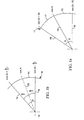
- Fig. 1a is a schematic drawing of the angles and values employed in "stepping around" the unit circle to locate roots of a line spectrum pair expression.
- Fig. 1b is a schematic drawing of angles and values employed in approximating the cosine of a bisecting angle of a sector given the cosines of boundary angles of the sector.
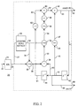
- Fig. 2 is a schematic drawing of the preferred embodiment of a waveform generating unit for use in the present invention.
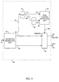
- Fig. 3 is a schematic drawing of the preferred embodiment of a polynomial zero crossing detector unit for use in the present invention.
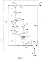
- Fig. 4 is a schematic drawing of the preferred embodiment of a half-angle generating unit for use in the present invention.
- Fig. 5 is a schematic drawing of the preferred embodiment of an angle bisecting unit for use in the present invention.
- Fig. 6 is a schematic drawing of the preferred embodiment of the apparatus of the present invention.
- Fig. 7 is a schematic diagram of an alternate embodiment of a waveform generating unit for use in the present invention.
- Fig. 8 is a flow diagram illustrating the preferred embodiment of the method of the present invention.
- a basic known canonical feedback digital filter transfer function appropriate for modeling a vocal tract may be expressed as:
- the most preferable quantization technique is the technique that uses the fewest bits in order to most efficiently employ the apparatus used for such transmission.
- the coefficient values a i have some undesirable qualities, such as: some coefficients a i are more sensitive than others; sometimes an error in one coefficient a i affects the entire spectrum sought to be represented.
- the apparatus and method of the present invention are appropriate for determining roots of the expressions which result from the LSP transformation.
- LPC linear predictive coding
- Line spectrum pair parameters may be derived from a consideration of two extreme artificial boundary conditions applied to LPC coefficients.
- the resulting LSP parameters can be interpreted as the resonant frequencies of the vocal tract under the two extreme artificial boundary conditions at the glottis.
- the two polynomials which involve the line spectrum pair parameters possess some interesting properties summarized as follows:
- each of the polynomials lie on the unit circle in the Z-plane (the complex plane) so that when the model (or the system represented by the model) is in equilibrium, the roots lie on the unit circle. Outside the unit circle the signal amplitude increases, and inside the unit circle the signal damps.
- each polynomial is expressed in terms of cos ⁇ .
- a useful method for more accurately determining the roots, at least approximately, of the LSP polynomials is by approximating the cosine of a bisecting angle within an interval given the cosine of the boundary angles, and determining in which half-angle interval the root lies.
- Equation (4) is the equation used in the preferred embodiment of the present invention to "step around" the unit circle to locate the five roots of an LSP polynomial expression. However, for ease in understanding the invention, the remaining discussions explaining the invention will be based upon the expression in Equation (3).
- Fig. 1a is a schematic drawing of the angles and values employed in "stepping around” the unit circle to locate roots of a line spectrum pair expression.
- ⁇ or the step angle used to "step around" a unit circle 11 to determine location of roots of a line spectrum pair expression is illustrated as being equal to B, so that the radii 16, 18 delineate a sector 15 of unit circle 11, and radii 18, 19 delineate a sector 17 of unit circle 11.
- cos ( A + B ) 2 cos B cos A -cos ( A - B )
- sector 15 has an upper limit equal to the value cos A and has a lower limit equal to the value cos(A - B).
- sector 17 has an upper limit equal to the value cos (A + B) and has a lower limit equal to the value cos A.
- the bisection of step angle B can be easily performed using a computer apparatus. Typically, in the preferred embodiment of the present invention, only a very small number of stored values of the expression will be required. By such successive bisection, the technique for determining a root of an LSP expression may be very efficiently performed to a desired accuracy.
- the cosines of the successively bisected step angles B, B / 2, B / 2 2 , ... B / 2 n may be calculated in sequence and stored as required.
- Equation (5) is difficult to calculate accurately for step angles B when using finite precision arithmetic, a common problem with computers. This difficulty arises from the loss of precision induced by leading nines in the value of cos B. For example, cos 1° equals 0.999847.
- Equation (8) requires the use of values of and further bisection will require use of the values It is useful to rewrite Equation (8) as:
- Equation (21) is sufficiently accurate.
- 1-(1-cos ( A + B )) 2 [1-(1-cos B )-(1-cos A ) + (1-cos A ) (1-cos B )] -1+(1-cos ( A + B ))
- Equation (28) enables one to configure a waveform generator accurately for small angle increments for implementation of the present invention.
- Fig. 1b is a schematic drawing of angles and values employed in approximating the cosine of a bisecting angle of a sector given the cosines of boundary angles of the sector.
- a unit circle 10 is illustrated as centered on a center point 12.
- a sector 14 of unit circle 10 is delineated by a lower limit at a radius 16 and an upper limit at a radius 18. Radii 16, 18 are separated by a step angle B. Step angle B is bisected to two half-step angles B / 2.
- a central point in sector 14 is defined as the value cos A at a point where a radius 20 intersects unit circle 10.
- Radius 20 is defined as a radius displaced from radius 16 by half-step angle B / 2. Consequently, the lower limit of sector 14 as defined by the intersection of radius 16 with unit circle 10 is a point having a value the upper limit of sector 14 defined by the intersection of radius 18 with unit circle 10 has a value of
- Equation (3) may be rewritten to fit the scheme of Fig. 1 as follows:
- n Increasing the value of n will increase accuracy of the model for determining that a root of an equation lies in a subdivided sector defined by a step angle of
- Equation (32) one can closely approximate cos A (the cosine of the angle bisecting sector 14 in Fig. 1) by using Equation (32), and one can approximate a sub-sector to any desired accuracy by further halving the sub-sector.
- Fig. 2 is a schematic drawing of the preferred embodiment of a waveform generating unit for use in the present invention.
- a waveform generating unit 20 which implements the expression of Equation (4).
- An input 22 provides an initial value for step angle B to a function generator 24 which provides an output (1 - cos B) on a line 26.
- Function generator 24 may be any known manner of device which takes an input such as a known step angle B and generates the value (1 - cos B) therefrom. That is, it may include a read only memory (ROM) or a random access memory (RAM), or a sinusoidal generating unit, or any other units known to those skilled in the art which can generate appropriate sinusoidal values.
- Line 26 provides the output from function generator 24 to a leading zero detect unit 28 via a line 27, and to a shift unit 30.
- Fig. 2 detects leading zeroes, contemplating storage and treatment of numbers within waveform generating unit 20 in decimal representation.
- other representation, storage and treatment formats will require somewhat different scaling techniques, such as detecting a sign bit and leading 1's or leading zeroes according to the value of the sign bit. Any scaling technique appropriate to a value representation approach is contemplated as applicable to and usable in the present invention.
- Leading zero detection is illustrated here in an exemplary role.
- Leading zero detect unit 28 provides an output at line 32 indicating the number m of leading zeros detected in the output provided via line 26, 27 from function generator 24 to leading zero detect unit 28.
- the number of leading zeros m is provided via a line 34 to shift unit 30 and shift unit 30 shifts m places to the left to effect a binary multiplication of 2 m in order to scale the output received via line 26 from function generator 24.
- a scaled value 2 m (1 - cos B) of the output value (1 - cos B) on line 26 is provided on line 36 to a multiplier 38.
- the radius is represented by radius 18 occurs later than radius 16, and the next-occurring phasor in stepping along unit circle 11 in Fig. 1a is represented by radius 19.
- Radius 19 intersects unit circle 11 at a point represented by the value cos (A + B).
- the signal on line 43 representing the value cos A is provided as an input to delay unit 44, as an input to multiplier 38, and to a scaling unit 46.
- Scaling unit 46 shifts digits in the signal carried on line 43 to the left one space to effect a binary multiplication by two.
- the signal on a line 47 is equal to two times the signal present on input line 45. That is, line 47 carries the value 2 cos A. Line 47 provides that value (2 cos A) as an input to adder 48.
- the signal carried on line 36 represents the value 2 m (1 - cos B) and is provided as a second input to multiplier 38.
- Multiplier 38 generates a signal on an output line 50 representing a value 2 m (cos A (1 - cos B)); the signal on line 50 is provided as an input to shift unit 52.
- Shift unit 52 shifts to the right m places (m being the number of leading zeroes detected by leading zero detect unit 28) to rescale the signal received from multiplier 38 via line 50.
- Shift unit 52 generates on an output line 54 a signal representing the value cos A (1 - cos B), which value is provided as an input to scaling unit 56.
- a multiplier 58 multiplies the output received from scaling unit 56 by the quantity - 1 and provides a signal to adder 60 which represents the value - 2 cos A (1 - cos B)
- Delay unit 44 generates a signal on a line 61 representing the value cos (A - B), which is the next-preceding phasor intersect on the unit circle 11 (see Fig. 1a).
- the value cos (A - B) is provided to a multiplier 62 which multiplies that value by - 1.
- Multiplier 62 provides a signal on a line 63 representing the value - cos (A - B) as a second input to adder 60.
- delay unit 42 must be initialized to cos (-B) and delay unit 44 must be initialized to zero to properly initiate operations.
- Adder 60 provides a signal on a line 64 representing the value - 2 cos A (1 - cos B) - cos (A - B) to adder 48.
- Adder 48 provides a signal on line 65 representing the sum of inputs received via lines 47, 64 [2 cos A - 2 cos A (1 - cos B) - cos (A - B)], which (by Equation (4)) equals the value cos A + B.
- the signal representing the value cos A is generated via a line 66 from line 43 to an output 68.
- Fig. 3 is a schematic drawing of the preferred embodiment of a polynomial zero crossing detector unit for use in the present invention.
- a polynomial zero crossing detector 69 is illustrated and includes a waveform generating unit 20 of the sort described in connection with Fig. 2.
- Waveform generating unit 20 receives an input 26 bearing a signal representing the value (1 - cos B).
- Waveform generating unit 20 generates the value cos (A + B) at an output 40, and generates a value cos A at an output 68.
- a line 70 delivers the value cos (A + B) from line 40 to a polynomial treating unit 72.
- Polynomial treating unit 72 receives the value cos (A + B) via line 70.
- Polynomial treating unit 72 evaluates the polynomial (preferably, in the present embodiment of the invention, a line spectrum pair polynomial) for the value received on line 70 and generates an evaluation value of that particular polynomial treated by polynomial treating unit 72 on an output line 74.
- the evaluation value of the particular polynomial treated by polynomial treating unit 72 for the value provided via line 70 is provided at an input 76 of a sign change detecting unit 78.
- a delay unit 80 also receives the output from polynomial treating unit 72 via a line 82 and generates an evaluation value for evaluation of the polynomial treated by polynomial treating unit 72 during a once-previous time. That is, the output of delay unit 80 on line 84 is an evaluation value for the polynomial treated by the polynomial treating unit 72 at the value cos A. This evaluation value for the polynomial at value cos A is provided to an input 86 of sign change detecting unit 78. Sign change detecting unit sends a sign change detected signal via a line 88 to a buffer 90.
- Buffer 90 also receives via line 40 the value cos (A + B), and via line 68 the value cos A.
- the sign change detected signal provided via line 88 to buffer 90 switches buffer 90 on when there is a sign change detected by sign change detecting unit 78.
- Output 92 of buffer 90 generates an output representing the value cos (A + B), and output 94 of buffer 90 generates an output representing the value cos A.
- Outputs 92, 94 are updated when a sign change is detected by sign change detector 78 and a sign change detected signal is provided via line 88 to buffer 90.
- the values of cos A + B (on line 40) and cos A (on line 68) are gated through buffer 90 to outputs 92, 94 when sign change detecting unit 78 detects a sign change between its signals received at inputs 76 and 86 and sends a sign change detected signal via line 88 to turn on buffer 90.
- the signals provided at outputs 92, 94 from buffer 90 are such that a zero (i.e., a root) of the polynomial treated by polynomial treating unit 72 lies between the angles A and (A + B), which are represented by the values cos A and cos (A + B)
- Fig. 4 is a schematic drawing of the preferred embodiment of a half-angle generating unit for use in the present invention.
- a half-angle generating unit 96 implements the expression of Equation (32).
- the output 102 of half-angle generating unit 96 carries a signal representing the value 1-cos B / 2 n +1 ⁇
- This signal is also applied via a line 104 to a delay unit 100.
- Delay unit 100 presents at its output line 106 a signal representing the value 1-cos B / 2 n .
- Reset values are occasionally provided to delay unit 100 via a line 98 representing the value (1-cos B).
- the output carried on line 106 is applied to a scaling unit 108 which shifts digits to the right two places to effect a division of the signal received via line 106 by four.
- the output of scaling unit 108 carried on line 110 is a signal which represents the value 1-cos B 2 n 4 . That signal is applied via a line 112 to a leading zero detect unit 114, is applied via a line 116 to a shift unit 118, and is applied via a line 120 to a summing unit 122.
- Leading zero detect unit 114 generates at an output line 124 a signal representing m, the number of leading zeros detected in the value received via line 112. As described before in discussing leading zero detection, any scaling apparatus appropriate for scaling numbers represented in a given format may be employed in place of leading zero detect unit 114.
- the value m is applied via a line 126 to shift unit 118, and via a line 128 to a scaling unit 130.
- Shift unit 118 shifts digits contained in the signal received via line 116 to the left m places to effect a multiplication by the quantity 2 m so that the output generated on line 132 from shift unit 118 represents the value
- Scaling unit 130 effects a shift to the left by one place to effect a multiplication by 2 to generate on a line 134 a signal representing the value 2m.
- the value 2m is applied via line 134 to a shift unit 136.
- the signal carried on line 132 is applied to a squaring unit 138.
- Squaring unit 138 generates an output signal line 140 representing the value
- the signal is applied via line 140 to shift unit 136; shift unit 136 generates an output signal on line 142 representing the value received via line 140 divided by
- a scaling unit 144 shifts digits in signals received via line 142 to the right one place to effect a division by 2 so that signals carried on an output line 146 from scaling unit 144 to summing unit 122 represent the value
- Summing unit 122 generates on an output line 148 the value As we know from Equation (31), that approximately equals 1-cos B / 2 n +1 .
- Fig. 5 is a schematic drawing of the preferred embodiment of an angle bisecting unit for use in the present invention.
- an angle bisecting unit 150 implements the expression of Equation (22).
- Angle bisecting unit 150 receives two inputs 152, 154 which are appropriate for connection with outputs 92, 94 of the polynomial zero crossing detector unit 69 illustrated in Fig. 3.
- input 152 receives a signal representing the value cos (A + B)
- input 154 receives a signal representing the value cos A.
- Both inputs 152, 154 are applied to a summing unit 156.
- Summing unit 156 generates a signal on a line 158 which represents the value cos (A + B) + cos A.
- Scaling unit 160 shifts digits contained in the signal provided on line 158 to the right one space, thereby effecting a binary division by two so that scaling unit 160 generates on a line 162 a signal representing the value cos( A + B ) + cos A 2 .
- Line 162 is connected to a multiplier 164.
- a second input to multiplier 164 is provided via a line 166.
- Line 166 carries a signal representing the value
- the output line 168 from multiplier 164 carries a signal representing the value According to Equation (22), that value equals
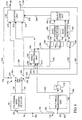
- Fig. 6 is a schematic drawing of the preferred embodiment of the apparatus of the present invention.
- a root determining apparatus 170 which includes a polynomial zero crossing detector 69 (Fig. 3), which includes a waveform generating unit 20 (Fig. 2); a half-angle generating unit 96 (Fig. 4); a delay unit 172; and switches 174, 176, 178. Also included in root determining apparatus 170 are an angle bisecting unit 150 (Fig. 5); polynomial treating units 180, 182, 184; zero crossing detectors 186, 188; a select logic unit 190; and a selector unit 192.
- An input is provided to root determining apparatus 170 via a line 194 in the form of a signal representing the value 1 - cos B.
- This input signal is provided via a line 26 to waveform generator 20 in polynomial zero crossing detector 69, and is also provided via a line 98 and a pole 198 of switch 178 to half-angle generating unit 96.
- Half-angle generating unit 96 generates a signal on a line 102 representing the value 1-cos B / 2 n +1 and provides that signal to delay unit 172 as well as to an input 214 of angle bisecting unit 150.
- Delay unit 172 generates a signal on a line 200 representing the value 1-cos B / 2 n and applies that value to a pole 202 of switch 178.
- Polynomial zero crossing detector 69 provides at its output 92 a signal representing the value cos (A + B), and applies that value to a pole 204 of switch 174. Polynomial zero crossing detector 69 also generates a signal on its output 94 representing the value cos A, and applies that signal to a pole 206 of switch 176.
- polynomial crossing detector 69 ensures that the values represented by the signals generated on outputs 92, 94 bracket a zero solution of the line spectrum pair polynomial treated by the polynomial treating unit 72 (Fig. 3) in polynomial zero crossing detector 69.
- Switches 174, 176, 178 are arranged for accommodating initial setup of root determining apparatus 170 in a first orientation and for accommodating segmenting operations of root determining apparatus 170 in a second orientation.
- root determining apparatus 170 is configured for initial/reset operation.
- the signal on output 92 is provided to a selector unit 192 at a selector unit input 210, and the signal on output 94 is applied to a selector unit input 212 of selector unit 192.
- the input carried on line 98 representing the value 1-cos B is applied to half-angle generating unit 96.
- the signal generated by half-angle generating unit 96 on line 102 is provided via a line 103 to an input 214 of angle bisecting unit 150.
- Angle bisecting unit 150 provides at its output 168 (Fig. 5) a signal representing the value which is applied to a selector unit input 213 of selector unit 192.
- selector unit 192 selects input signals representing the quantity cos ( A + B ) for application to its output 216 as the upper limit U p of a sector (such as sector 15 of Fig. 1a) and selector unit 192 selects signals representing the quantity cos A from selector unit input 212 for application to its output 218 to represent the lower limit L p of a sector such as sector 15 of Fig. 1a.
- selector unit 192 does not consider signals appearing at its input 213 for application to its outputs 216, 218.
- root determining apparatus 170 does not involve angle bisecting unit 150 in determining upper limit U p and lower limit L p outputs for its outputs 216, 218.
- root determining apparatus 170 remains in its initial/reset operation configuration as root determining apparatus 170 "steps around" unit circle 11 in increments established as sectors 15, 17 (Fig. 1a). This is so in the case where the coarse (or first cut) estimation of location of roots on the unit circle suffices and there is no need to further segment sector 15 (Fig. 1a) to more finely determine location of roots on unit circle 11.
- angle bisecting unit 150 is operationally included in root determining apparatus 170 so that upper limit U p is provided via a feedback line 224 and a line 226 to an input 228 of angle bisecting unit 150.
- lower limit L p is provided via a feedback line 230 and a line 232 to an input 234 of angle bisecting unit 150.
- input from delay unit 172 is provided via line 200 and via switch 178 to the input of half-angle generating unit 96.
- line 226 provides upper limit U p to a polynomial treating unit 180
- line 232 provides lower limit L p to polynomial treating unit 184
- output 168 from bisecting unit 150 is provided via a line 236 to a polynomial treating unit 182.
- Polynomial treating units 180, 182, 184 preferably are similar to polynomial treating unit 72 (Fig. 3) in that they each provide an evaluation value to the polynomial for which roots are sought by root determining apparatus 170 for the values provided via their respective input lines 226, 236, 232.
- an evaluation value for the polynomial for which roots are sought by root determining apparatus 170 is provided for the value received via line 226 by polynomial treating unit 180 on an output line 240 to a zero crossing detector 186.
- An evaluation value for the polynomial for which roots are sought is provided for the value received via input 236 by polynomial treating unit 182 on an output 242 to zero crossing detector 186 and to a zero crossing detector 188.
- an evaluation value for the polynomial for which roots are sought is provided for the value provided via input 232 on an output line 244 to zero crossing detector 188.
- Zero crossing detector 186 provides an output via a line 246 to a select logic unit 190
- zero crossing detector 188 provides an output via a line 248 to select logic unit 190.
- select logic unit 190 receives an indication via lines 246, 248 whether a zero crossing occurs between the values cos ( A + B ) and (via line 246) or whether a zero crossing occurs between the values cos A and (via line 248).
- select logic unit 190 selects values to define the interval containing the zero crossing: an upper half-sector between lower limit and upper limit cos (A + B), or a lower half-sector between lower limit cos A and upper limit A signal is provided by select logic unit 190 via a line 250 to an input 252 to selector unit 192 indicating which half-sector contains the zero crossing.
- Selector unit 192 contains logic which (1) defines a sector having an upper limit U p (on output 216) set to the value received via input and having a lower limit L p (on output 218) set to the value received via input 212 [cos A] when the input from select logic unit 192 via line 250 indicates that the zero crossing occurred in the lower half-sector bounded by cos A and or (2) defines a sector having an upper limit U p set to the value received via input 210 [cos A + B], and having a lower limit L p set to the value received via input when select logic unit 190 outputs a signal to selector unit 192 via line 250 that indicates the zero crossing occurred in the upper half-sector bounded by values and cos (A + B).
- delay unit 172 delivers via line 200 and switch 178 to the input of half-angle generating unit 96 a signal representing 1-cos B / 2 n .
- Half-angle generating unit 96 provides a signal representing 1-cos B / 2 n +1 to input 214 of angle bisecting unit 150 via lines 102, 103.
- Angle bisecting unit 150 uses inputs received at input 214 to further bisect sector 15 whereby each half-sector is now reestablished as a newly-defined sector having an upper limit U p and a lower limit L p which is then bisected.
- Zero crossing is determined to be either in the lower half-sector (line 248 to select logic 190) or in the upper half-sector (line 246 to select logic unit 190) of one of the newly-defined sectors.
- Selector unit 192 proceeds with the half-sector containing a zero crossing as a next-newly-defined sector for the next bisecting iteration.
- Fig. 7 is a schematic diagram of an alternate embodiment of a waveform generating unit for use in the present invention.
- Fig. 7 illustrates a waveform generating unit for use in the present invention when angles A and B are small enough that leading nines in the quantities cos A or cos B indicate it is useful to use quantities (1 - cos A) or (1 - cos B) in their place to ensure that all digits used to represent the required values in root determination operations are significant digits.
- Fig. 7 implements Equation (28) to enable one to configure a waveform generator accurately for small angle increments for implementation of the present invention.
- a waveform generating unit 260 receives an input on a line 262 representing the quantity (1 - cos B).
- the input received via line 262 is provided via a line 264 to a leading zero detect unit 266 and, via a line 268, to a summing unit 270.
- Leading zero detect unit 266 generates an output on a line 272 representing the number m of leading zeroes detected in the input received via line 264.
- leading zero detect unit 266 may be replaced by any scaling apparatus appropriate to the number format used.
- the signal representing m is applied via a line 274 to a scaling unit 276, and is provided via a line 278 to a scaling unit 280.
- the input signal applied at input line 262 is applied to scaling unit 276 so that scaling unit 276 provides a signal on line 282 representing the signal received via line 262 multiplied times 2 m .
- the output signal provided at output 284 of waveform generating unit 260 is a signal representing the quantity 1 - cos (A + B), and the output signal provided at output 286 is a signal representing the quantity 1 - cos A.
- Delay unit 288 receives the signal provided at output 284 via a feedback line 290 so that the output provided on line 292 from delay unit 288 is a signal representing the quantity 1 - cos A. That signal is provided to a delay unit 294, to a multiplier 296, and to output 286 via a line 311.
- delay units 288, 294 must be appropriately initialized to ensure proper operation of waveform generating unit 260.
- Delay unit 294 generates a signal on an output line 298 representing the quantity 1 - cos (A - B), which signal is applied to a multiplier 300.
- Multiplier 300 effects a multiplication by the quantity - 1.
- Multiplier 296 multiplies the value received via line 282 (i.e., 2 m (1 - cos B)) times the value received via line 292 (i.e., 1 - cos A) and generates a signal on a line 302 representing the quantity 2 m (1 - cos A) (1 - cos B).
- Multiplier 303 multiplies the value received via line 302 by the quantity -1, and produces on line 305 a signal representing the quantity -2 m (1 - cos A) (1 - cos B)
- Multiplier 300 generates a signal on a line 304 representing the quantity - (1 - cos (A - B)).
- the signal carried on line 304 is applied to a summing unit 306.
- the signal carried on line 305 is applied to scaling unit 280.
- Scaling unit 280 provides a signal on line 308 representing the signal received via line 302 divided by 2 m , so that scaling unit 280 generates on line 308 a signal representing the value - (1 - cos A) (1 - cos B), which signal is applied to summing unit 270.
- the signal carried on line 292 representing 1 - cos A is also applied via a line 309 to summing unit 270.
- Summing unit 270 generates a signal on a line 310 representing the value - (1 - cos A) (1 - cos B) + (1 - cos A) + (1 - cos B)
- the signal carried on line 310 is applied to a scaling unit 312 to multiply the signal received via line 310 times 2.
- Scaling unit 312 generates a signal on a line 314 representing the value 2 ((1 - cos A) - (1 - cos A) (1 - cos B) + (1 - cos B)).
- the signal carried on line 314 is applied to summing unit 306 so that summing unit 306 generates on output line 284 a signal representing the quantity 2 ((1 - cos A) - (1 - cos A) (1 - cos B) + (1 - cos B)) - (1 - cos (A - B)).
- Equation (28) we know from Equation (28) that the quantity represented by the signal on line 284 equals the value 1 - cos (A + B).
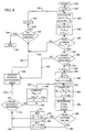
- Figure 8 is a flow diagram illustrating the preferred embodiment of the method of the present invention.
- the method begins with "Start" at block 320 and a counter n is set to 0 at block 322.
- an inquiry is made whether a sign change occurred in the values of the polynomial G(X) in the interval between X n-1 and X n .
- the "No" branch 348 is taken to a function block 350 which effects outputting the interval containing the root (X n-1 , X n ) and then proceeds via branch 352 to decision block 332 for determination whether all intervals on unit circle 11 have been checked. Subsequent decisions and operations occur as described above in connection with answers to the query posed by decision block 332.
- a counter p is set at block 356 and provided via branch 358 to block 360.
- an upper limit U p is set equal to X n
- a lower limit L p is set equal to X n-1
- the value M p indicated in block 364 is the midpoint of the particular segment being addressed by block 364 and equals the value Using the values computed in blocks 360, 364, block 366 evaluates the polynomial G(X) for those values and provides evaluation values to decision block 368.
- Decision block 368 determines whether there is a sign change in the interval between lower limit L p and midpoint M p . If there is such a sign change, then the root of the polynomial G(X) is in the lower half-sector in the interval L p , M p of the sector determined in block 324 and bounded by X n-1 , X n . "Yes" branch 370 is taken so that the next iterative sector limits for possible subsequent bisecting of the sector are established in block 372 for a newly-defined sector: a newly-defined lower limit L p+1 being set at the original lower limit L p , and a newly-defined upper limit U p+1 being set at the midpoint M p .
- the method may continue in this loop (from decision block 368, to block 372, to decision block 374, to block 380, to block 364, and to block 366) until the response to the query posed by decision block 374 is negative, indicating that sufficient accuracy had been achieved in root location determination, whence the method proceeds via "No" branch 376 from decision block 374 as previously described.
- decision block 368 determines that no sign change has occurred in the interval L p , M p . If decision block 368 determines that no sign change has occurred in the interval L p , M p , then "No" branch 384 is taken from decision block 368 to block 386.
- a newly-defined lower limit L p+1 is set at midpoint M p and a newly-defined upper limit U p+1 is set at upper limit U p .
- Those newly-defined limits L p+1 , U p+1 delimit a newly-defined sector established by block 386 which is the upper half-sector of the sector defined in block 360. Block 386 provides these newly-defined limit values via a branch 388 to decision block 374 and the method proceeds thereafter as previously described.
Landscapes
- Engineering & Computer Science (AREA)
- Physics & Mathematics (AREA)
- General Physics & Mathematics (AREA)
- Mathematical Physics (AREA)
- Computational Linguistics (AREA)
- Health & Medical Sciences (AREA)
- Audiology, Speech & Language Pathology (AREA)
- Human Computer Interaction (AREA)
- Acoustics & Sound (AREA)
- Multimedia (AREA)
- Theoretical Computer Science (AREA)
- Data Mining & Analysis (AREA)
- Mathematical Optimization (AREA)
- Computational Mathematics (AREA)
- Signal Processing (AREA)
- Pure & Applied Mathematics (AREA)
- Mathematical Analysis (AREA)
- Software Systems (AREA)
- Databases & Information Systems (AREA)
- Algebra (AREA)
- General Engineering & Computer Science (AREA)
- Operations Research (AREA)
- Spectroscopy & Molecular Physics (AREA)
- Compression, Expansion, Code Conversion, And Decoders (AREA)
- Measurement Of Mechanical Vibrations Or Ultrasonic Waves (AREA)
- Position Fixing By Use Of Radio Waves (AREA)
- Length Measuring Devices With Unspecified Measuring Means (AREA)
- Image Analysis (AREA)
- Complex Calculations (AREA)
Claims (19)
- Vorrichtung zum Analysieren von Sprachsignalen zwecks Bestimmen von Parametern, die repräsentativ für Eigenschaften der Sprachsignale sind, mit:gekennzeichnet durcheiner Linear-Vorauskodierungs-(LPC-)Analyseeinheit, die zum Konvertieren von Sprachsignalen zu LPC-Parametern konfiguriert ist,einer Transformationseinheit, die zum Transformieren der LPC-Parameter zu einem entsprechenden Linienspektrumpaar-(LSP-)Ausdruck konfiguriert ist;eine Wellenformerzeugungseinheit (20) mit einem ersten Eingang (22) zum Empfangen einer Darstellung eines Anfangswerts zum Lokalisieren einer ersten Stelle auf dem Einheitskreis (10), und mit einem zweiten Eingang zum Empfangen einer Darstellung eines Schritt-Werts zum Definieren eines Bogenabstandes auf dem Einheitskreis (10); wobei die Wellenformerzeugungseinheit (20) auf dem Einheitskreis (10) mehrere Intervalle (15,17) erzeugt, wobei jedes Intervall (15,17) der mehreren Intervalle (15,17) einen unteren Grenzwert und einen oberen Grenzwert hat, und die mehreren Intervalle (15,17) ein Anfangs-Intervall (15) und mehrere sukzessive Intervalle (17) aufweisen; wobei der untere Grenzwert des Anfangs-Intervalls (15) der Anfangswert ist und der obere Grenzwert des Anfangs-Intervalls (15) auf dem Einheitskreis (10) relativ zu dem Anfangswert um den Bogen-Abstand versetzt ist; wobei der jeweilige untere Grenzwert jedes jeweiligen sukzessiven Intervalls (17) der mehreren sukzessiven Intervalle (17) mit dem oberen Grenzwert des nächstvorhergehenden Intervalls der mehreren Intervalle (15,17) übereinstimmt, wobei der jeweilige obere Grenzwert jedes jeweiligen sukzessiven Intervalls auf dem Einheitskreis (10) relativ zu seinem jeweiligen unteren Grenzwert um den Bogenabstand versetzt ist; undeiner mit der Wellenformerzeugungseinheit (20) verbundenen Polynom-Nuii-Detektionseinheit (69), die die mehreren Intervalle (15,17) empfängt und den Linienspektrumpaar-Ausdruck (408) für mindestens den oberen Grenzwert und den unteren Grenzwert für jedes jeweilige Intervall der mehreren Intervalle (15,17) auswertet; wobei die Polynom-Null-Detektionseinheit (69) das Vorhandensein einer jeweiligen Wurzel der mehreren Wurzeln erkennt, wenn der Linienspektrumpaar-Ausdruck (408) innerhalb eines bestimmten Intervalls der mehreren Intervalle (15,17) sein Vorzeichen verändert, wobei die Polynom-Null-Detektionseinheit (69) jedes derartige bestimmte Intervall als ein Lösungs-Intervall bezeichnet; wobei die Polynom-Null-Detektionseinheit (69) den unteren Grenzwert und den oberen Grenzwert jedes Lösungs-Intervalls erzeugt;
wobei die in den Lösungs-Intervallen vorhandenen mehreren Wurzeln die Eigenschaften der Sprachsignale ausdrücken;einer mit der Polynom-Null-Detektionseinheit (69) verbundenen Winkelhalbierungseinheit (150), die das Lösungs-Intervall empfängt und eine Halbierungs-Operation durchführt, welche ein unteres Fein-Lösungs-Intervall und ein oberes Fein-Lösungs-Intervall definiert; undeiner Wähl-Einheit (190), die mit der Winkelhalbierungseinheit (150) und mit der Polynom-Null-Detektionseinheit (69) verbunden ist; wobei die Wähl-Einheit (190) ein unteres Grenzwert-Ausgangssignal und ein oberes Grenzwert-Ausgangssignal erzeugt, um entsprechend anzugeben, ob die jeweilige Wurzel sich in dem unteren Fein-Lösungs-Intervall oder in dem oberen Fein-Lösungs-Intervall befindet. - Vorrichtung zum Analysieren von Sprachsignalen nach Anspruch 1, ferner mit:einer mit dem zweiten Eingang der Wellenformerzeugungseinheit (20) verbundenen Halbabstandserzeugungseinheit (96), die einen Halbbogenabstand erzeugt, wobei der Halbbogenabstand die Hälfte des Bogenabstandes beträgt;wobei die Winkelhalbierungseinheit (150) mit der Halbabstandserzeugungseinheit (96) verbunden ist, die Winkelhalbierungseinheit (150) den Halbbogenabstand empfängt; das untere Fein-Lösungs-Intervall einen unteren Fein-Unter-Grenzwert an dem unteren Grenzwert des Lösungs-Intervalls und einen unteren Fein-Ober-Grenzwert hat, der an dem Einheits-Kreis (10) relativ zu dem unteren Fein-Unter-Grenzwert um den Halbbogenabstand versetzt ist; wobei das obere Fein-Lösungs-Intervall einen oberen Fein-Ober-Grenzwert an dem oberen Grenzwert des Lösungs-Intervalls und einen oberen Fein-Unter-Grenzwert hat, der an dem Einheits-Kreis (10) relativ zu dem oberen Fein-Ober-Grenzwert um den Halb-Bogenabstand versetzt ist.
- Vorrichtung zum Analysieren von Sprachsignalen nach Anspruch 2, bei der die Halbabstandserzeugungseinheit (96) und die Winkelhalbierungseinheit (150) zum sukzessiven Durchführen der Halbierungs-Operation derart zusammenwirken, dass sie jedes Lösungs-Intervall iterativ in ein sukzessives oberes Fein-Lösungs-Intervall und ein sukzessives unteres Fein-Lösungs-Intervall halbieren, wobei die jeweilige Wurzel innerhalb des sukzessiven oberen Fein-Lösungs-Intervalls oder des sukzessiven unteren Fein-Lösungs-Intervalls angeordnet ist, wobei die sukzessive Halbierungs-Operation iterativ durchgeführt wird, bis eine vorbestimmte gewünschte Präzision der Bogenlänge in einem sukzessiven Fein-Lösungs-Intervall vorhanden ist.
- Vorrichtung zum Analysieren von Sprachsignalen nach Anspruch 1, bei der der Anfangswert als ein Sinuswert einer Winkelverschiebung an dem Einheits-Kreis (10) ausgedrückt wird und bei der der Schritt-Wert als ein Sinuswert der Schrittwinkelverschiebung an dem Einheits-Kreis (10) ausgedrückt wird.
- Vorrichtung zum Analysieren von Sprachsignalen nach Anspruch 2, bei der der Anfangswert als ein Sinuswert einer Winkelverschiebung an dem Einheits-Kreis (10) ausgedrückt wird und bei der der Schritt-Wert als ein Sinuswert der Schrittwinkelverschiebung an dem Einheits-Kreis (10) ausgedrückt wird.
- Verfahren zum Analysieren von Sprachsignalen zwecks Bestimmen von Parametern, die repräsentativ für Eigenschaften der Sprachsignale (400) sind, mit den folgenden Schritten:Konvertieren von Sprachsignalen zu Linear-Vorauskodierungs-(LPC-)Parametern;Transformieren der LPC-Parameter zu einem entsprechenden Linienspektrumpaar-(LSP-)Ausdruck; gekennzeichnet durchLokalisieren mehrerer Wurzeln des LSP-Ausdrucks, wobei die Wurzeln die Parameter sind, die die Sprach-Eigenschaften repräsentieren, mit den folgenden Schritten:Empfangen einer Darstellung eines Anfangswerts zum Lokalisieren einer ersten Stelle auf dem Einheits-Kreis (10);Empfangen einer Darstellung eines Schritt-Werts zum Definieren eines Bogenabstands auf dem Einheits-Kreis (10);Erzeugen mehrerer Intervalle (15,17) auf dem Einheits-Kreis (10), wobei jedes Intervall der mehreren Intervalle (15,17) einen unteren Grenzwert und einen oberen Grenzwert hat, wobei die mehreren Intervalle ein Anfangs-Intervall (15) und mehrere sukzessive Intervalle (17) enthalten; wobei der untere Grenzwert des Anfangs-Intervalls (15) der Anfangs-Wert ist, der obere Grenzwert des Anfangs-Intervalls (15) auf dem Einheits-Kreis (10) relativ zu dem Anfangs-Wert um den Bogenabstand versetzt ist; wobei der jeweilige untere Grenzwert jedes jeweiligen sukzessiven Intervalls der mehreren sukzessiven Intervalle (17) mit dem oberen Grenzwert des nächstvorhergehenden Intervalls der mehreren Intervalle (15,17) übereinstimmt, wobei der jeweilige obere Grenzwert jedes jeweiligen sukzessiven Intervalls auf dem Einheitskreis (10) relativ zu seinem jeweiligen unteren Grenzwert um den Bogenabstand versetzt ist;Evaluieren des Linienspektrumpaar-Ausdrucks für mindestens den oberen Grenzwert und den unteren Grenzwert jedes jeweiligen Intervalls der mehreren Intervalle (15,17);Erkennen des Vorhandenseins einer jeweiligen Wurzel der mehreren Wurzeln, wenn der Linienspektrumpaar-Ausdruck innerhalb eines bestimmten Intervalls der mehreren Intervalle (15,17) sein Vorzeichen verändert,Bezeichnen jedes derartigen bestimmten Intervalls als ein Lösungs-Intervall;Erzeugen des unteren Grenzwerts und des oberen Grenzwerts jedes Lösungs-Intervalls, wobei die in den Lösungs-Intervallen vorhandenen mehreren Wurzeln die Eigenschaften der Sprachsignale ausdrücken;Durchführen einer Halbierungs-Operation, die ein unteres Fein-Lösungs-Intervall und ein oberes Fein-Lösungs-Intervall definiert; undErzeugen eines unteren Grenzwert-Ausgangssignals und eines oberen Grenzwert-Ausgangssignals, um entsprechend anzugeben, ob die jeweilige Wurzel sich in dem unteren Fein-Lösungs-Intervall oder in dem oberen Fein-Lösungs-Intervall befindet.
- Verfahren zum Analysieren von Sprachsignalen nach Anspruch 6, ferner mit den folgenden Schritten:Erzeugen eines Halbbogenabstandes, der die Hälfte des Bogenabstandes beträgt;wobei das untere Fein-Lösungs-Intervall einen unteren Fein-Unter-Grenzwert an dem unteren Grenzwert des Lösungs-Intervalls und einen unteren Fein-Ober-Grenzwert hat, der an dem Einheits-Kreis (10) relativ zu dem unteren Fein-Unter-Grenzwert um den Halbbogenabstand versetzt ist; wobei das obere Fein-Lösungs-Intervall einen oberen Fein-Ober-Grenzwert an dem oberen Grenzwert des Lösungs-Intervalls und einen oberen Fein-Unter-Grenzwert aufweist, der an dem Einheits-Kreis relativ zu dem oberen Fein-Ober-Grenzwert um den Halb-Bogenabstand versetzt ist.
- Verfahren zum Analysieren von Sprachsignalen nach Anspruch 7, ferner mit den folgenden Schritten:sukzessives Durchführen der Halbierungs-Operation zum iterativen Halbieren jedes Lösungs-Intervalls in ein sukzessives oberes Fein-Lösungs-Intervall und ein sukzessives unteres Fein-Lösungs-Intervall, wobei die jeweilige Wurzel innerhalb des sukzessiven oberen Fein-Lösungs-Intervalls und/oder des sukzessiven unteren Feln-Lösungs-Intervalls angeordnet ist, wobei die sukzessive Halbierungs-Operation iterativ durchgeführt wird, bis eine vorbestimmte gewünschte Präzision der Bogenlänge in einem sukzessiven Fein-Lösungs-Intervall vorhanden ist.
- Verfahren zum Analysieren von Sprachsignalen nach Anspruch 6, bei dem der Anfangswert als ein Sinuswert einer Winkelverschiebung an dem Einheits-Kreis (10) ausgedrückt wird und bei dem der Schritt-Wert als ein Sinuswert einer Schrittwinkelverschiebung an dem Einheits-Kreis (10) ausgedrückt wird.
- Verfahren zum Analysieren von Sprachsignalen nach Anspruch 7, bei dem der Anfangswert als ein Sinuswert einer Winkelverschiebung an dem Einheits-Kreis (10) ausgedrückt wird und bei dem der Schritt-Wert als ein Sinuswert einer Schrittwinkelverschiebung an dem Einheits-Kreis (10) ausgedrückt wird.
- Computervorrichtung zum Analysieren von Sprachsignalen zwecks Bestimmen von Parametern, die repräsentativ für Eigenschaften der Sprachsignale sind, mit:einer Linear-Vorauskodlerungs-(LPC-)Analyseeinrichtung zum Konvertieren von Sprachsignalen zu LPC-Parametern;einer Transformationseinrichtung zum Transformieren der LPC-Parameter zu einem entsprechenden Linienspektrumpaar-(LSP-)Ausdruck;
gekennzeichnet durcheine Wellenformerzeugungseinrichtung (20) zum Erzeugen eines unteren Grenzwerts und eines oberen Grenzwerts für jedes jeweilige Intervall mehrerer Intervalle (15,17) auf dem Einheits-Kreis (10); wobei die mehreren Intervalle (15,17) aneinander angrenzen und jedes jeweilige Intervall sich um einen vorbestimmten Bogenabstand hinzieht;eine mit der Wellenformerzeugungseinrichtung (20) verbundene Wurzeldetektionseinrichtung (170) zum Detektieren der Wurzeln; wobei die Wurzeldetektionseinrichtung (170) die unteren Grenzwerte und die oberen Grenzwerte empfängt und einen Evaluationswert für den Linienspektrumpaar-Ausdruck für mindestens den oberen Grenzwert und den unteren Grenzwert für jedes jeweilige Intervall (15,17) bestimmt; wobei die Wurzeldetektionseinrichtung (170) ein bestimmtes der jeweiligen Intervalle (15,17) als Lösungs-Intervall bezeichnet, wenn der Evaluationswert innerhalb des bestimmten jeweiligen Intervalls sein Vorzeichen ändert;
wobei die Wurzeldetektionseinrichtung (170) den unteren Grenzwert und den oberen Grenzwert jedes Lösungs-Intervalls erzeugt; wobei die mehreren in den Lösungs-Intervallen vorhandenen Wurzeln die Eigenschaften der Sprachsignale ausdrücken;eine mit der Wurzeldetektionseinrichtung (170) verbundenen Winkelhalbierungseinrichtung (150) zum Empfangen des Lösungs-Intervalls und Durchführen einer Halbierungs-Operation, die ein unteres Fein-Lösungs-Intervall und ein oberes Fein-Lösungs-Intervall definiert; undeine mit der Winkelhalbierungseinrichtung (150) und mit der Wurzeldetektionseinrichtung (170) verbundenen Wähl-Einheit (190) zum Erzeugen eines unteren Grenzwert-Ausgangssignals und eines oberen Grenzwert-Ausgangssignals, um entsprechend anzugeben, ob die jeweilige Wurzel sich in dem unteren Fein-Lösungs-Intervall oder in dem oberen Fein-Lösungs-Intervall befindet. - Vorrichtung zum Analysieren von Sprachsignalen nach Anspruch 11, ferner mit:wobei der Halbbogenabstand die Hälfte des Bogenabstandes beträgt;einer mit der Wellenformerzeugungseinheit (20) verbundenen Halbabstandserzeugungseinheit (96) zum Erzeugen eines Halbbogenabstands,
wobei die Winkelhalbierungseinheit (150) mit der Halbabstandserzeugungseinheit (96) verbunden ist, um das Lösungs-Intervall zu empfangen, wobei das untere Fein-Lösungs-Intervall einen unteren Fein-Unter-Grenzwert an dem unteren Grenzwert des Lösungs-Intervalls und einen unteren Fein-Ober-Grenzwert hat, der an dem Einheits-Kreis (10) relativ zu dem unteren Fein-Unter-Grenzwert um den Halbbogenabstand versetzt ist; wobei das obere Fein-Lösungs-Intervall einen oberen Fein-Ober-Grenzwert an dem oberen Grenzwert des Lösungs-Intervalls und einen oberen Fein-Unter-Grenzwert hat, der an dem Einheits-Kreis (10) relativ zu dem oberen Fein-Ober-Grenzwert um den Halb-Bogenabstand versetzt ist. - Vorrichtung zum Analysieren von Sprachsignalen nach Anspruch 12, bei der die Halbabstandserzeugungseinheit (96) und die Winkelhalbierungseinheit (150) zum sukzessiven Durchführen der Halbierungs-Operation derart zusammenwirken, dass sie jedes Lösungs-Intervall iterativ in ein sukzessives oberes Fein-Lösungs-Intervall und ein sukzessives unteres Fein-Lösungs-Intervall halbieren, wobei die jeweilige Wurzel innerhalb des sukzessiven oberen Fein-Lösungs-Intervalls und/oder des sukzessiven unteren Fein-Lösungs-Intervalls angeordnet ist, wobei die sukzessive Halbierungs-Operation iterativ durchgeführt wird, bis eine vorbestimmte gewünschte Präzision der Bogenlänge in einem sukzessiven Fein-Lösungs-Intervall vorhanden ist.
- Vorrichtung zum Analysieren von Sprachsignalen zwecks Bestimmen von Parametern, die repräsentativ für Eigenschaften der Sprachsignale sind, mit:gekennzeichnet durcheiner Linear-Vorauskodierungs-(LPC-)Analyseeinheit, die zum Konvertieren von Sprachsignalen zu LPC-Parametern konfiguriert ist,einer Transformationseinheit, die zum Transformieren der LPC-Parameter zu einem entsprechenden Linienspektrumpaar-(LSP-)Ausdruck konfiguriert ist;eine Digitai-Weiienformerzeugungseinheit (20) mit einem ersten Wellenform-Eingang (22) zum Empfangen eines Anfangs-Werts zum Lokalisieren einer Wellenform-Stelle auf dem Einheits-Kreis (10), einem zweiten Wellenform-Eingang zum Empfangen einer Darstellung eines Schritt-Werts zum Definieren eines Bogenabstandes auf dem Einheitskreis (10), und einem Wellenform-Ausgang (92,94) zum Ausgeben mehrerer Intervalle (15,17), wobei die Wellenformerzeugungseinheit (20) die mehreren Intervalle (15,17) auf dem Einheits-Kreis (10) erzeugt, jedes Intervall der mehreren Intervalle (15,17) einen unteren Grenzwert und einen oberen Grenzwert hat, wobei eine Differenz zwischen dem oberen Grenzwert und dem unteren Grenzwert der Schritt-Wert ist; undeiner Digital-Polynom-Null-Detektionseinheit (69) mit einer Linienspektrumpaar-Polynom-Einheit (72), einer Verzögerungseinheit (80), einer Vorzeichenveränderungs-Detektionseinheit (78) und einem Puffer (90), wobei die Linienspektrumpaar-Polynom-Einheit (72) einen mit dem Wellenform-Ausgang (40) der Wellenformerzeugungseinheit (20) verbundenen Einheiten-Eingang (70) und einen Einheiten-Ausgang (74) aufweist, wobei die Polynom-Einheit (72) ein Polynom-Ausgangssignal an dem Einheiten-Ausgang (74) ausgibt, die Verzögerungseinheit (80) einen mit dem Einheiten-Ausgang (74) verbundenen Verzögerungs-Eingang (82) und einen Verzögerungs-Ausgang (84) aufweist, wobei die Verzögerungseinheit (80) ein verzögertes Ausgangssignal an dem Verzögerungs-Ausgang (84) ausgibt, die Vorzeichenveränderungs-Detektionseinheit (78) einen mit dem Einheiten-Ausgang (74) verbundenen ersten Detektions-Eingang (76), einen mit dem Verzögerungs-Ausgang (84) verbundenen zweiten Detektions-Eingang (86) und einen mit dem Puffer (90) verbundenen Detektions-Ausgang (88) aufweist, wobei die Puffer-Einheit (90) ein an dem Wellenform-Ausgang (40) ausgegebenes Intervall der Intervalle (15,17) speichert, wenn die Vorzeichenveränderungs-Detektionseinheit (78) eine Vorzeichen-Veränderung zwischen dem an dem ersten Detektions-Eingang (76) empfangenen Polynom-Ausgangssignal und dem an dem zweiten Detektions-Eingang (86) empfangenen Verzögerungs-Ausgangssignal feststellt, wobei das in dem Puffer (90) gespeicherte Intervall eine der mehreren Wurzeln des Linienspektrumpaar-Ausdrucks (408) repräsentiert; wobei die mehreren in den Intervallen (15,17) vorhandenen Wurzeln die Eigenschaften der Sprachsignale repräsentieren; undeiner mit der Digital-Wellenformerzeugungseinheit (20) verbundenen Halbabstandserzeugungseinheit (96) zum Reduzieren der Differenz zwischen den aus der Digital-Wellenformerzeugungseinheit (20) zugeführten oberen und unteren Grenzwerten.
- Vorrichtung zum Analysieren von Sprachsignalen nach Anspruch 14, bei der der obere und der untere Grenzwert als Sinuswert repräsentiert werden.
- Vorrichtung zum Analysieren von Sprachsignalen nach Anspruch 14, bei der die Digital-Wellenformerzeugungseinheit (20) einen RAM-Speicher aufweist.
- Vorrichtung zum Analysieren von Sprachsignalen nach Anspruch 14, bei der die Digital-Wellenformerzeugungseinheit (20) mehrere Addier- und Verzögerungs-Einheiten aufweist.
- Vorrichtung zum Analysieren von Sprachsignalen nach Anspruch 14, bei der die Digital-Weilenformerzeugungseinheit (20) ferner einen Funktionsgenerator aufweist, der einen Wert von 1-cos eines gewählten Winkels erzeugt.
- Vorrichtung zum Analysieren von Sprachsignalen nach Anspruch 14, bei der die Digitai-Welienformerzeugungseinheit (20) ferner eine Nulldetektions-Einheit (28) aufweist.
Applications Claiming Priority (2)
| Application Number | Priority Date | Filing Date | Title |
|---|---|---|---|
| US31837994A | 1994-10-05 | 1994-10-05 | |
| US318379 | 1994-10-05 |
Publications (3)
| Publication Number | Publication Date |
|---|---|
| EP0710948A2 EP0710948A2 (de) | 1996-05-08 |
| EP0710948A3 EP0710948A3 (de) | 1997-12-29 |
| EP0710948B1 true EP0710948B1 (de) | 2002-02-27 |
Family
ID=23237932
Family Applications (1)
| Application Number | Title | Priority Date | Filing Date |
|---|---|---|---|
| EP95306470A Expired - Lifetime EP0710948B1 (de) | 1994-10-05 | 1995-09-14 | Vorrichtung und Verfahren zur Sprachsignalanalyse zur Parameterbestimmung von Sprachsignalmerkmalen |
Country Status (5)
| Country | Link |
|---|---|
| US (1) | US5745648A (de) |
| EP (1) | EP0710948B1 (de) |
| KR (1) | KR100354325B1 (de) |
| AT (1) | ATE213864T1 (de) |
| DE (1) | DE69525590D1 (de) |
Families Citing this family (2)
| Publication number | Priority date | Publication date | Assignee | Title |
|---|---|---|---|---|
| JP3842432B2 (ja) | 1998-04-20 | 2006-11-08 | 株式会社東芝 | ベクトル量子化方法 |
| KR100429180B1 (ko) * | 1998-08-08 | 2004-06-16 | 엘지전자 주식회사 | 음성 패킷의 파라미터 특성을 이용한 오류 검사 방법 |
Family Cites Families (7)
| Publication number | Priority date | Publication date | Assignee | Title |
|---|---|---|---|---|
| JPS5853352B2 (ja) * | 1979-10-03 | 1983-11-29 | 日本電信電話株式会社 | 音声合成器 |
| CA1245363A (en) * | 1985-03-20 | 1988-11-22 | Tetsu Taguchi | Pattern matching vocoder |
| US5012518A (en) * | 1989-07-26 | 1991-04-30 | Itt Corporation | Low-bit-rate speech coder using LPC data reduction processing |
| US4975956A (en) * | 1989-07-26 | 1990-12-04 | Itt Corporation | Low-bit-rate speech coder using LPC data reduction processing |
| EP1998319B1 (de) * | 1991-06-11 | 2010-08-11 | Qualcomm Incorporated | Vocoder mit veränderlicher Bitrate |
| US5305421A (en) * | 1991-08-28 | 1994-04-19 | Itt Corporation | Low bit rate speech coding system and compression |
| US5448680A (en) * | 1992-02-12 | 1995-09-05 | The United States Of America As Represented By The Secretary Of The Navy | Voice communication processing system |
-
1995
- 1995-09-14 EP EP95306470A patent/EP0710948B1/de not_active Expired - Lifetime
- 1995-09-14 AT AT95306470T patent/ATE213864T1/de not_active IP Right Cessation
- 1995-09-14 DE DE69525590T patent/DE69525590D1/de not_active Expired - Lifetime
- 1995-10-05 KR KR1019950034100A patent/KR100354325B1/ko not_active Expired - Fee Related
-
1997
- 1997-05-05 US US08/851,411 patent/US5745648A/en not_active Expired - Lifetime
Also Published As
| Publication number | Publication date |
|---|---|
| KR960015380A (ko) | 1996-05-22 |
| ATE213864T1 (de) | 2002-03-15 |
| DE69525590D1 (de) | 2002-04-04 |
| EP0710948A2 (de) | 1996-05-08 |
| US5745648A (en) | 1998-04-28 |
| EP0710948A3 (de) | 1997-12-29 |
| KR100354325B1 (ko) | 2003-01-15 |
Similar Documents
| Publication | Publication Date | Title |
|---|---|---|
| US6594626B2 (en) | Voice encoding and voice decoding using an adaptive codebook and an algebraic codebook | |
| US5195137A (en) | Method of and apparatus for generating auxiliary information for expediting sparse codebook search | |
| US6122608A (en) | Method for switched-predictive quantization | |
| US5077798A (en) | Method and system for voice coding based on vector quantization | |
| US4944013A (en) | Multi-pulse speech coder | |
| EP0337636B1 (de) | Anordnung zur harmonischen Sprachcodierung | |
| US4393272A (en) | Sound synthesizer | |
| JPS63113600A (ja) | 音声信号の符号化及び復号化のための方法及び装置 | |
| US5097508A (en) | Digital speech coder having improved long term lag parameter determination | |
| US20070118370A1 (en) | Methods and apparatuses for variable dimension vector quantization | |
| EP0842509B1 (de) | Verfahren und vorrichtung zur erzeugung und kodierung von linienspektralwurzeln | |
| EP0235180B1 (de) | Sprachsynthese unter verwendung von verschiedenen anregungsformen | |
| US5721543A (en) | System and method for modeling discrete data sequences | |
| EP0882287B1 (de) | System und verfahren zur fehlerkorrektur in einer auf korrelation basierenden grundfrequenzschätzvorrichtung | |
| CN103348597A (zh) | 低比特率信号编码器及解码器 | |
| EP0710948A2 (de) | Vorrichtung und Verfahren zur Bestimmung mehrerer Wurzeln eines "Line-Spectrum-Pair"-Ausdrucks auf dem Einheitskreis | |
| WO2002013180A1 (en) | Digital signal processing method, learning method, apparatuses for them, and program storage medium | |
| US7412384B2 (en) | Digital signal processing method, learning method, apparatuses for them, and program storage medium | |
| US5704001A (en) | Sensitivity weighted vector quantization of line spectral pair frequencies | |
| AU577641B2 (en) | Relp vocoder implemented in digital signal processors | |
| JPH0782360B2 (ja) | 音声分析合成方法 | |
| WO1994018573A1 (en) | Non-harmonic analysis of waveform data and synthesizing processing system | |
| JPH09114496A (ja) | 単位円上で線スペクトル対の式の複数の根を標定するための装置およびその方法 | |
| EP0470941A1 (de) | Verfahren zur Kodierung eines abgetasteten Sprachsignalvektors | |
| EP0774750A2 (de) | Bestimmung der Linienspektrumfrequenzen zur Verwendung in einem Funkfernsprecher |
Legal Events
| Date | Code | Title | Description |
|---|---|---|---|
| PUAI | Public reference made under article 153(3) epc to a published international application that has entered the european phase |
Free format text: ORIGINAL CODE: 0009012 |
|
| AK | Designated contracting states |
Kind code of ref document: A2 Designated state(s): AT BE DE DK ES FR GB GR IE IT LU NL PT SE |
|
| 17P | Request for examination filed |
Effective date: 19960826 |
|
| PUAL | Search report despatched |
Free format text: ORIGINAL CODE: 0009013 |
|
| AK | Designated contracting states |
Kind code of ref document: A3 Designated state(s): AT BE DE DK ES FR GB GR IE IT LU NL PT SE |
|
| 17Q | First examination report despatched |
Effective date: 19991126 |
|
| GRAG | Despatch of communication of intention to grant |
Free format text: ORIGINAL CODE: EPIDOS AGRA |
|
| RIC1 | Information provided on ipc code assigned before grant |
Free format text: 7G 10L 19/06 A |
|
| RTI1 | Title (correction) |
Free format text: APPARATUS AND METHOD FOR ANALYZING SPEECH SIGNALS TO DETERMINE PARAMETERS EXPRESSIVE OF CHARACTERISTICS OF THE SPEECH SIGNALS |
|
| GRAG | Despatch of communication of intention to grant |
Free format text: ORIGINAL CODE: EPIDOS AGRA |
|
| GRAG | Despatch of communication of intention to grant |
Free format text: ORIGINAL CODE: EPIDOS AGRA |
|
| GRAH | Despatch of communication of intention to grant a patent |
Free format text: ORIGINAL CODE: EPIDOS IGRA |
|
| GRAH | Despatch of communication of intention to grant a patent |
Free format text: ORIGINAL CODE: EPIDOS IGRA |
|
| REG | Reference to a national code |
Ref country code: GB Ref legal event code: IF02 |
|
| GRAA | (expected) grant |
Free format text: ORIGINAL CODE: 0009210 |
|
| AK | Designated contracting states |
Kind code of ref document: B1 Designated state(s): AT BE DE DK ES FR GB GR IE IT LU NL PT SE |
|
| PG25 | Lapsed in a contracting state [announced via postgrant information from national office to epo] |
Ref country code: NL Free format text: LAPSE BECAUSE OF FAILURE TO SUBMIT A TRANSLATION OF THE DESCRIPTION OR TO PAY THE FEE WITHIN THE PRESCRIBED TIME-LIMIT Effective date: 20020227 Ref country code: IT Free format text: LAPSE BECAUSE OF FAILURE TO SUBMIT A TRANSLATION OF THE DESCRIPTION OR TO PAY THE FEE WITHIN THE PRESCRIBED TIME-LIMIT;WARNING: LAPSES OF ITALIAN PATENTS WITH EFFECTIVE DATE BEFORE 2007 MAY HAVE OCCURRED AT ANY TIME BEFORE 2007. THE CORRECT EFFECTIVE DATE MAY BE DIFFERENT FROM THE ONE RECORDED. Effective date: 20020227 Ref country code: GR Free format text: LAPSE BECAUSE OF FAILURE TO SUBMIT A TRANSLATION OF THE DESCRIPTION OR TO PAY THE FEE WITHIN THE PRESCRIBED TIME-LIMIT Effective date: 20020227 Ref country code: FR Free format text: LAPSE BECAUSE OF FAILURE TO SUBMIT A TRANSLATION OF THE DESCRIPTION OR TO PAY THE FEE WITHIN THE PRESCRIBED TIME-LIMIT Effective date: 20020227 Ref country code: BE Free format text: LAPSE BECAUSE OF FAILURE TO SUBMIT A TRANSLATION OF THE DESCRIPTION OR TO PAY THE FEE WITHIN THE PRESCRIBED TIME-LIMIT Effective date: 20020227 Ref country code: AT Free format text: LAPSE BECAUSE OF FAILURE TO SUBMIT A TRANSLATION OF THE DESCRIPTION OR TO PAY THE FEE WITHIN THE PRESCRIBED TIME-LIMIT Effective date: 20020227 |
|
| REF | Corresponds to: |
Ref document number: 213864 Country of ref document: AT Date of ref document: 20020315 Kind code of ref document: T |
|
| REF | Corresponds to: |
Ref document number: 69525590 Country of ref document: DE Date of ref document: 20020404 |
|
| PG25 | Lapsed in a contracting state [announced via postgrant information from national office to epo] |
Ref country code: SE Free format text: LAPSE BECAUSE OF FAILURE TO SUBMIT A TRANSLATION OF THE DESCRIPTION OR TO PAY THE FEE WITHIN THE PRESCRIBED TIME-LIMIT Effective date: 20020527 Ref country code: PT Free format text: LAPSE BECAUSE OF FAILURE TO SUBMIT A TRANSLATION OF THE DESCRIPTION OR TO PAY THE FEE WITHIN THE PRESCRIBED TIME-LIMIT Effective date: 20020527 Ref country code: DK Free format text: LAPSE BECAUSE OF FAILURE TO SUBMIT A TRANSLATION OF THE DESCRIPTION OR TO PAY THE FEE WITHIN THE PRESCRIBED TIME-LIMIT Effective date: 20020527 |
|
| PG25 | Lapsed in a contracting state [announced via postgrant information from national office to epo] |
Ref country code: DE Free format text: LAPSE BECAUSE OF FAILURE TO SUBMIT A TRANSLATION OF THE DESCRIPTION OR TO PAY THE FEE WITHIN THE PRESCRIBED TIME-LIMIT Effective date: 20020528 |
|
| NLV1 | Nl: lapsed or annulled due to failure to fulfill the requirements of art. 29p and 29m of the patents act | ||
| PGFP | Annual fee paid to national office [announced via postgrant information from national office to epo] |
Ref country code: GB Payment date: 20020808 Year of fee payment: 8 |
|
| PG25 | Lapsed in a contracting state [announced via postgrant information from national office to epo] |
Ref country code: ES Free format text: LAPSE BECAUSE OF FAILURE TO SUBMIT A TRANSLATION OF THE DESCRIPTION OR TO PAY THE FEE WITHIN THE PRESCRIBED TIME-LIMIT Effective date: 20020829 |
|
| PG25 | Lapsed in a contracting state [announced via postgrant information from national office to epo] |
Ref country code: LU Free format text: LAPSE BECAUSE OF NON-PAYMENT OF DUE FEES Effective date: 20020914 |
|
| PG25 | Lapsed in a contracting state [announced via postgrant information from national office to epo] |
Ref country code: IE Free format text: LAPSE BECAUSE OF NON-PAYMENT OF DUE FEES Effective date: 20020916 |
|
| EN | Fr: translation not filed | ||
| PLBE | No opposition filed within time limit |
Free format text: ORIGINAL CODE: 0009261 |
|
| STAA | Information on the status of an ep patent application or granted ep patent |
Free format text: STATUS: NO OPPOSITION FILED WITHIN TIME LIMIT |
|
| 26N | No opposition filed |
Effective date: 20021128 |
|
| REG | Reference to a national code |
Ref country code: IE Ref legal event code: MM4A |
|
| PG25 | Lapsed in a contracting state [announced via postgrant information from national office to epo] |
Ref country code: GB Free format text: LAPSE BECAUSE OF NON-PAYMENT OF DUE FEES Effective date: 20030914 |
|
| GBPC | Gb: european patent ceased through non-payment of renewal fee |
Effective date: 20030914 |