EP0711009A2 - Connecteur électrique - Google Patents
Connecteur électrique Download PDFInfo
- Publication number
- EP0711009A2 EP0711009A2 EP95116923A EP95116923A EP0711009A2 EP 0711009 A2 EP0711009 A2 EP 0711009A2 EP 95116923 A EP95116923 A EP 95116923A EP 95116923 A EP95116923 A EP 95116923A EP 0711009 A2 EP0711009 A2 EP 0711009A2
- Authority
- EP
- European Patent Office
- Prior art keywords
- contact
- electrical plug
- plug connection
- connection according
- area
- Prior art date
- Legal status (The legal status is an assumption and is not a legal conclusion. Google has not performed a legal analysis and makes no representation as to the accuracy of the status listed.)
- Granted
Links
- 239000002184 metal Substances 0.000 claims abstract description 9
- 238000005452 bending Methods 0.000 claims description 7
- 238000003466 welding Methods 0.000 claims description 6
- 238000000034 method Methods 0.000 claims description 4
- 230000001681 protective effect Effects 0.000 claims description 3
- 238000006073 displacement reaction Methods 0.000 claims description 2
- 238000009413 insulation Methods 0.000 claims description 2
- 230000015572 biosynthetic process Effects 0.000 claims 1
- 238000012423 maintenance Methods 0.000 claims 1
- 238000004519 manufacturing process Methods 0.000 claims 1
- 229940099990 ogen Drugs 0.000 claims 1
- 230000000149 penetrating effect Effects 0.000 claims 1
- 230000005540 biological transmission Effects 0.000 description 2
- 230000003993 interaction Effects 0.000 description 2
- 241001465754 Metazoa Species 0.000 description 1
- 239000000463 material Substances 0.000 description 1
- 230000005405 multipole Effects 0.000 description 1
- 238000007493 shaping process Methods 0.000 description 1
Images


Classifications
-
- H—ELECTRICITY
- H01—ELECTRIC ELEMENTS
- H01R—ELECTRICALLY-CONDUCTIVE CONNECTIONS; STRUCTURAL ASSOCIATIONS OF A PLURALITY OF MUTUALLY-INSULATED ELECTRICAL CONNECTING ELEMENTS; COUPLING DEVICES; CURRENT COLLECTORS
- H01R13/00—Details of coupling devices of the kinds covered by groups H01R12/70 or H01R24/00 - H01R33/00
- H01R13/02—Contact members
- H01R13/15—Pins, blades or sockets having separate spring member for producing or increasing contact pressure
- H01R13/187—Pins, blades or sockets having separate spring member for producing or increasing contact pressure with spring member in the socket
-
- H—ELECTRICITY
- H01—ELECTRIC ELEMENTS
- H01R—ELECTRICALLY-CONDUCTIVE CONNECTIONS; STRUCTURAL ASSOCIATIONS OF A PLURALITY OF MUTUALLY-INSULATED ELECTRICAL CONNECTING ELEMENTS; COUPLING DEVICES; CURRENT COLLECTORS
- H01R13/00—Details of coupling devices of the kinds covered by groups H01R12/70 or H01R24/00 - H01R33/00
- H01R13/02—Contact members
- H01R13/35—Contact members for non-simultaneous co-operation with different types of contact member, e.g. socket co-operating with either round or flat pin
-
- H—ELECTRICITY
- H01—ELECTRIC ELEMENTS
- H01R—ELECTRICALLY-CONDUCTIVE CONNECTIONS; STRUCTURAL ASSOCIATIONS OF A PLURALITY OF MUTUALLY-INSULATED ELECTRICAL CONNECTING ELEMENTS; COUPLING DEVICES; CURRENT COLLECTORS
- H01R13/00—Details of coupling devices of the kinds covered by groups H01R12/70 or H01R24/00 - H01R33/00
- H01R13/02—Contact members
- H01R13/10—Sockets for co-operation with pins or blades
- H01R13/11—Resilient sockets
- H01R13/113—Resilient sockets co-operating with pins or blades having a rectangular transverse section
-
- H—ELECTRICITY
- H01—ELECTRIC ELEMENTS
- H01R—ELECTRICALLY-CONDUCTIVE CONNECTIONS; STRUCTURAL ASSOCIATIONS OF A PLURALITY OF MUTUALLY-INSULATED ELECTRICAL CONNECTING ELEMENTS; COUPLING DEVICES; CURRENT COLLECTORS
- H01R4/00—Electrically-conductive connections between two or more conductive members in direct contact, i.e. touching one another; Means for effecting or maintaining such contact; Electrically-conductive connections having two or more spaced connecting locations for conductors and using contact members penetrating insulation
- H01R4/02—Soldered or welded connections
-
- H—ELECTRICITY
- H01—ELECTRIC ELEMENTS
- H01R—ELECTRICALLY-CONDUCTIVE CONNECTIONS; STRUCTURAL ASSOCIATIONS OF A PLURALITY OF MUTUALLY-INSULATED ELECTRICAL CONNECTING ELEMENTS; COUPLING DEVICES; CURRENT COLLECTORS
- H01R4/00—Electrically-conductive connections between two or more conductive members in direct contact, i.e. touching one another; Means for effecting or maintaining such contact; Electrically-conductive connections having two or more spaced connecting locations for conductors and using contact members penetrating insulation
- H01R4/10—Electrically-conductive connections between two or more conductive members in direct contact, i.e. touching one another; Means for effecting or maintaining such contact; Electrically-conductive connections having two or more spaced connecting locations for conductors and using contact members penetrating insulation effected solely by twisting, wrapping, bending, crimping, or other permanent deformation
- H01R4/18—Electrically-conductive connections between two or more conductive members in direct contact, i.e. touching one another; Means for effecting or maintaining such contact; Electrically-conductive connections having two or more spaced connecting locations for conductors and using contact members penetrating insulation effected solely by twisting, wrapping, bending, crimping, or other permanent deformation by crimping
Definitions
- the present invention is based on an electrical connector designed according to the preamble of the main claim.
- Such electrical connectors are intended to be connected via their socket part and their plug part e.g. to produce a releasable electrical connection between an electrical line and a further electrical line or an electrical line and an electrical unit.
- An electrical connector designed according to the preamble of the main claim has become known from DE 38 17 803 C2.
- This electrical connector consists of a rectangular plug part and a socket part.
- the socket part consists of a base body made of sheet metal by stamping and bending, the contact area of which is rectangular in cross section and is intended for connection to the plug part and is provided for the quiver-like reception of a separate contact means.
- the separate Contact means for contacting with the plug part has a plurality of longitudinally parallel contact webs, and is also rectangular in cross section by multiple bending.
- the cage-like contact means is pushed into the quiver-like contact area of the base body until a funnel flange formed thereon strikes the free front end of the base body and a locking projection formed on the base body comes to rest in a locking opening provided in the contact means.
- the base body can be connected to the contact material by means of a weld.
- an electrical socket part has become known from DE 39 06 625 C1, in which the contact means consists of a contact plate which is bent in a U-shape around the central zone running transversely to its longitudinal extent, so that two mutually parallel contact arms arranged opposite one another are formed are.
- this contact means is assigned to a solidly designed base body and is positively and non-positively attached to the base body via its central zone connecting the two contact arms.
- the present invention has for its object to provide an electrical connector that can be made particularly inexpensive in a simple manner and at the same time a good power transmission between the socket part consisting of contact means and base body and the plug part is guaranteed.
- the free end regions of the contact arms are connected to the mouth region of the base body both in a form-fitting and material-locking manner, so that the contact means can expand in the plug-in direction when making contact with the plug part, and the plug-in forces occurring in contact animals are comparatively low . This is particularly desirable in the case of multi-pole electrical connector arrangements.
- an unspecified housing for example made of plastic, also belongs to an electrical connector arrangement.
- a housing part is assigned to the socket part (s) and a housing part is assigned to the plug part (s).
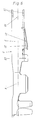
- such an electrical plug connection consists of a plug part 1 with a rectangular cross section and a socket part.
- the socket part in turn consists of a base body 2 produced from sheet metal by stamping and bending, which has a contact area 3 provided for connection to the plug part 1 and a connection area 4 provided for connecting an electrical line.
- the contact area 3 is designed as a quiver with a rectangular cross section, from which a separate contact means 6, provided with a plurality of contact webs 5, is held. To hold the contact means 6 is pushed into the quiver-like contact area 3 of the base body 2 in the plug-in direction during assembly.
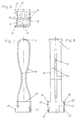
- the contact means 6 consists of an originally flat contact plate.
- the sheet metal blank is bent to produce the contact means 6 in a U-shape around the central zone 7, which extends transversely to its longitudinal extent, so that two contact arms 8, which run essentially parallel to one another, are produced.
- Each of the two contact arms 8 thus has two contact webs 5.
- the two contact webs 5 of the two contact arms 8 are arranged opposite one another and set in a bottle neck-like manner to form defined contact points.
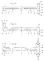
- the free end regions of the two contact arms 8 are designed differently.
- the free end region 11 of which, in the finished state, is designed as a rectangular frame at least one of the two contact arms 8 has at least one web-like extension 10.
- a web-like extension 10 is formed on each of the two long sides of one of the two contact arms 8, so that the free end of this contact arm 8 has a T-shaped contour.
- a cross-sectionally U-shaped end region of this contact arm 8 is created. Because the other contact arm 8 is ultimately received between the two web-like extensions 10 during the shaping process of the contact plate, a contact means 6 is formed, the free end region 11 of which rectangular frame is formed.
- a web-like extension 10 is formed diagonally opposite one of the two long sides of the two contact arms 8. After the web-like extensions 10 have been bent, free ends of the two contact arms 8 are formed, each of which has an L-shaped contour in cross section. Because in the end the web-like extension 10 of one contact arm 8 comes into contact with the free end of the other contact arm 8 and the web-like extension 10 of the other contact arm 8 comes into contact with the free end of the one contact arm 8 due to the forming process of the contact plate, a contact means 6 is formed, the free end region 11 is formed as a rectangular frame.
- a fastening tab 13 is formed on each of the web-like extensions 10 of the contact arms 8.
- the fastening tabs 13 extend perpendicular to the main surfaces of the two contact arms 8, whereby they protrude beyond one of the outer walls of the free end region 11 of the contact means 6. This results in a receiving pocket 14 with a U-shaped cross section, via which the contact means 6 is positively and materially connected to the contact area 3 of the base body 2.
- a web-like extension 10 is formed on each of the two longitudinal sides of the one contact arm 8, so that a T-shaped free end is formed.
- Two fastening tabs 13 are formed on each of the two web-like extensions 10, between each of which there is a stop lug 12. Since the two fastening tabs 13 are longer than the stop lugs 12, a holding recess 15 is formed, into which a holding wing 16 molded onto the other contact arm 8 engages in a form-fitting manner after the forming process of the contact plate.
- the base body 2 consists of a contact area 3 and a connection area 4.
- the contact area 3 is designed as a rectangular quiver, on the mouth area of which two fastening prongs 17 are formed.
- the two fastening prongs 17 are provided for the form-fitting and material-fitting fastening of the contact means 6 to be assembled.
- Each of the three contact means variants described above and shown in FIGS. 7 to 12 can be received by the contact area 3 of the base body 2.
- FIGS. 1 to 5 only the equipping of the base body 2 with a contact means variant is shown in FIGS. 1 to 5.
- the contact medium variant used is the contact medium 6 shown in more detail in FIGS. 7 to 10.
- the contact means 6 is inserted in the plug-in direction of the plug part 1 into the contact area 3 of the base body 2, which is rectangular in cross-section and is quiver-like.
- One of the two fastening tines 17 formed on the mouth region of the contact region 3 comes to rest in the U-shaped receiving pocket 14 formed by the two fastening tabs 13.
- the other of the two fastening prongs 17 bears against the side wall of the free end region 11 of the contact means 6, which is formed as a rectangular frame, in relation to the receiving pocket 14.
- the contact means 6 is pushed into the contact area 3 until the free end area 11 with its end walls 18 assigned to the connection area 4 comes into contact with the mouth walls 19 of the contact area 3.
- the contact means 6 is positively received by the contact area 3 of the base body 2.
- the contact means 6 is also welded to the contact area 3.
- the mutually assigned punched edges of the fastening prong 17 arranged in the receiving pocket 14 and the two fastening tabs 13 forming the receiving pocket 14 are connected to one another via welding points 20 (see in particular FIGS. 3 to 5).
- a spring-elastic latching arm 21 is shown in one piece from the contact area 3.
- a protective tab 22 from the contact area 3 is also shown extending approximately parallel to the latching arm 21.
- the protective flap 22 serves as a catch protection, so that the socket parts e.g. do not get caught accidentally during transport.
- a locking lug 23 is molded onto the end of the contact area 3 assigned to the connection area 4 (see in particular FIGS. 1, 2 and 6).
- the locking nose works e.g. together with a locking slide to be inserted into the housing.
- connection region 4 of the base body 2 provided for connection to an electrical line is designed as a so-called crimp zone.
- the connection area can also have a different design, so that e.g. a so-called insulation displacement zone is created.
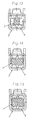
- the contact area 3 with its contact means 6, as can be seen in particular from FIGS. 13 to 15, is designed such that plug parts 1 of different design are contacted in terms of their dimensions and contours can.
- the socket part is suitable to contact 3 rectangular plug parts 1 via its contact area, the width of which starts from the narrowest contactable plug part 1 to max. twice as wide and its height starting from the lowest contactable plug part 1 to max. can be made a third more powerful. It is irrelevant whether the plug parts 1 to be contacted are designed as posts having a square cross section or as flat knives having a rectangular cross section.
Landscapes
- Connector Housings Or Holding Contact Members (AREA)
- Details Of Connecting Devices For Male And Female Coupling (AREA)
- Coupling Device And Connection With Printed Circuit (AREA)
Applications Claiming Priority (2)
| Application Number | Priority Date | Filing Date | Title |
|---|---|---|---|
| DE4439105 | 1994-11-02 | ||
| DE4439105A DE4439105C1 (de) | 1994-11-02 | 1994-11-02 | Elektrische Steckverbindung |
Publications (3)
| Publication Number | Publication Date |
|---|---|
| EP0711009A2 true EP0711009A2 (fr) | 1996-05-08 |
| EP0711009A3 EP0711009A3 (fr) | 1997-12-03 |
| EP0711009B1 EP0711009B1 (fr) | 2000-01-05 |
Family
ID=6532294
Family Applications (1)
| Application Number | Title | Priority Date | Filing Date |
|---|---|---|---|
| EP95116923A Expired - Lifetime EP0711009B1 (fr) | 1994-11-02 | 1995-10-27 | Connecteur électrique |
Country Status (6)
| Country | Link |
|---|---|
| US (1) | US5613885A (fr) |
| EP (1) | EP0711009B1 (fr) |
| JP (1) | JPH08236185A (fr) |
| BR (1) | BR9504908A (fr) |
| DE (2) | DE4439105C1 (fr) |
| ES (1) | ES2142986T3 (fr) |
Cited By (3)
| Publication number | Priority date | Publication date | Assignee | Title |
|---|---|---|---|---|
| EP1215763A1 (fr) * | 2000-10-12 | 2002-06-19 | Tyco Electronics AMP GmbH | Contact femelle pour un connecteur électrique |
| DE102006006316B3 (de) * | 2006-02-11 | 2007-10-31 | Tyco Electronics Amp Gmbh | Elektrischer Buchsenkontakt |
| US11329400B2 (en) | 2019-11-22 | 2022-05-10 | Lear Corporation | Multiple-piece female electrical terminal |
Families Citing this family (23)
| Publication number | Priority date | Publication date | Assignee | Title |
|---|---|---|---|---|
| DE69624309T2 (de) * | 1995-09-12 | 2003-05-22 | The Whitaker Corp., Wilmington | Elektrisches Anschlussteil mit Verriegelungszunge |
| FR2741204A1 (fr) * | 1995-11-14 | 1997-05-16 | Amp France | Assemblage de connecteur electrique |
| US5957734A (en) * | 1998-01-21 | 1999-09-28 | General Motors Corporation | Tuning fork inline connection system |
| US20040116002A1 (en) * | 2000-12-07 | 2004-06-17 | Dominique Rozet | Female contact having a cage structure comprising a blade-holder module |
| DE60216679T2 (de) * | 2001-08-30 | 2007-10-04 | Tyco Electronics Amp Gmbh | Kontakt mit verbessertem Verriegelungselement |
| US20030060090A1 (en) * | 2001-09-21 | 2003-03-27 | Allgood Christopher L. | High current automotive electrical connector and terminal |
| DE10244946B4 (de) * | 2001-10-10 | 2011-08-11 | Tyco Electronics AMP GmbH, 64625 | Kontaktbuchse für eine elektrische Steckverbindung |
| JP2003338334A (ja) * | 2002-05-20 | 2003-11-28 | Yazaki Corp | 雌端子およびその接続構造ならびにワイヤハーネス |
| DE10340850A1 (de) * | 2002-10-08 | 2004-04-22 | Tyco Electronics Amp Gmbh | Mechanisch stabilisierte Kontaktbuchse |
| US7241185B1 (en) * | 2005-12-22 | 2007-07-10 | Tensolite Company | Integral bonding attachment |
| US7896712B2 (en) * | 2005-12-22 | 2011-03-01 | Tensolite, Llc | Integral bonding attachment |
| DE102006053152B3 (de) * | 2006-11-10 | 2008-04-10 | Tyco Electronics Amp Gmbh | Elektrischer Buchsenkontakt |
| DE102007016070A1 (de) * | 2007-04-03 | 2008-10-09 | Lear Corp., Southfield | Elektrische Anschlussanordnung und Verfahren zum Nutzen der elektrischen Anschlussanordnung |
| DE102007031194B4 (de) * | 2007-07-04 | 2019-06-19 | Weidmüller Interface GmbH & Co. KG | Federklemme, Anordnung aus Federklemmen und Verfahren zur Montage von Federklemmen an einem Bauelement |
| US7985104B2 (en) * | 2007-07-05 | 2011-07-26 | Hirschmann Automotive Gmbh | Shield sleeve for a plug connector |
| CH704749B1 (fr) * | 2007-09-05 | 2012-10-15 | Preci Dip Sa | Clip de contact. |
| DE102008042050A1 (de) | 2008-09-12 | 2010-03-18 | Robert Bosch Gmbh | Leistungs-Steckkontakt sowie Leiterplattenanordnung |
| EP2797173B8 (fr) * | 2013-04-26 | 2019-01-09 | Aptiv Technologies Limited | Borne électrique pourvue d'une lance de verrouillage et son procédé de fabrication |
| AU2016204548A1 (en) * | 2015-07-07 | 2017-02-02 | Hayward Industries, Inc. | Spade Connector and Associated Systems and Methods |
| DE102016007117A1 (de) | 2016-06-11 | 2017-12-14 | Kostal Kontakt Systeme Gmbh | Kontaktlamelle für ein buchsenartiges Steckverbinderteil und buchsenartiges Steckverbinderteil |
| DE102017100021B4 (de) * | 2017-01-02 | 2020-07-30 | Te Connectivity Germany Gmbh | Buchsenkontakt und Kontaktsystem |
| DE102017001166A1 (de) | 2017-01-31 | 2018-08-02 | Kostal Kontakt Systeme Gmbh | Kontaktlamelle für ein buchsenartiges Steckverbinderteil und buchsenartiges Steckverbinderteil |
| EP3451467B1 (fr) * | 2017-09-01 | 2022-02-23 | Tyco Electronics France SAS | Contact électrique d'une feuille de métal ayant une languette d'encliquetage et/ou une butée de fin de course allongée plastiquement et son procédé de fabrication |
Citations (2)
| Publication number | Priority date | Publication date | Assignee | Title |
|---|---|---|---|---|
| DE3817803A1 (de) | 1988-05-26 | 1989-11-30 | Reinshagen Kabelwerk Gmbh | Elektrische flachsteckverbindung |
| DE3906625C1 (de) | 1989-03-02 | 1990-01-18 | Kostal Leopold Gmbh & Co Kg | Elektrisches Steckkontaktteil |
Family Cites Families (6)
| Publication number | Priority date | Publication date | Assignee | Title |
|---|---|---|---|---|
| US3123429A (en) * | 1961-04-27 | 1964-03-03 | Electrical contact socket | |
| US3894785A (en) * | 1972-04-18 | 1975-07-15 | Bunker Ramo | Connector |
| US5188545A (en) * | 1990-06-05 | 1993-02-23 | Amp Incorporated | Electrical socket terminal |
| DE4035613A1 (de) * | 1990-11-09 | 1992-05-14 | Daut & Rietz Trw | Flachkontaktsteckhuelse |
| EP0517077B1 (fr) * | 1991-06-03 | 1997-07-23 | The Whitaker Corporation | Contact électrique |
| JP3285101B2 (ja) * | 1993-01-21 | 2002-05-27 | 矢崎総業株式会社 | 雌型端子 |
-
1994
- 1994-11-02 DE DE4439105A patent/DE4439105C1/de not_active Expired - Fee Related
-
1995
- 1995-10-27 ES ES95116923T patent/ES2142986T3/es not_active Expired - Lifetime
- 1995-10-27 DE DE59507570T patent/DE59507570D1/de not_active Expired - Fee Related
- 1995-10-27 EP EP95116923A patent/EP0711009B1/fr not_active Expired - Lifetime
- 1995-11-01 US US08/548,339 patent/US5613885A/en not_active Expired - Fee Related
- 1995-11-01 JP JP7285095A patent/JPH08236185A/ja active Pending
- 1995-11-01 BR BR9504908A patent/BR9504908A/pt not_active IP Right Cessation
Patent Citations (2)
| Publication number | Priority date | Publication date | Assignee | Title |
|---|---|---|---|---|
| DE3817803A1 (de) | 1988-05-26 | 1989-11-30 | Reinshagen Kabelwerk Gmbh | Elektrische flachsteckverbindung |
| DE3906625C1 (de) | 1989-03-02 | 1990-01-18 | Kostal Leopold Gmbh & Co Kg | Elektrisches Steckkontaktteil |
Cited By (4)
| Publication number | Priority date | Publication date | Assignee | Title |
|---|---|---|---|---|
| EP1215763A1 (fr) * | 2000-10-12 | 2002-06-19 | Tyco Electronics AMP GmbH | Contact femelle pour un connecteur électrique |
| DE102006006316B3 (de) * | 2006-02-11 | 2007-10-31 | Tyco Electronics Amp Gmbh | Elektrischer Buchsenkontakt |
| US11329400B2 (en) | 2019-11-22 | 2022-05-10 | Lear Corporation | Multiple-piece female electrical terminal |
| DE102019218072B4 (de) | 2019-11-22 | 2023-06-01 | Lear Corporation | Mehrteilige elektrische Anschlussbuchse |
Also Published As
| Publication number | Publication date |
|---|---|
| US5613885A (en) | 1997-03-25 |
| DE59507570D1 (de) | 2000-02-10 |
| DE4439105C1 (de) | 1996-04-25 |
| JPH08236185A (ja) | 1996-09-13 |
| EP0711009A3 (fr) | 1997-12-03 |
| EP0711009B1 (fr) | 2000-01-05 |
| BR9504908A (pt) | 1997-09-02 |
| ES2142986T3 (es) | 2000-05-01 |
Similar Documents
| Publication | Publication Date | Title |
|---|---|---|
| DE4439105C1 (de) | Elektrische Steckverbindung | |
| EP4280397B1 (fr) | Cadre de retenue pour connecteur à fiche | |
| DE102014009208B4 (de) | Elektrische anschlussanordnung | |
| DE102013113975C5 (de) | Halterahmen für einen Steckverbinder | |
| EP3080874B2 (fr) | Cadre de retenue pour un connecteur par enfichage | |
| DE10121654B4 (de) | Kästchenförmiger Kontakt mit Beanspruchungsbegrenzung | |
| EP1503457B1 (fr) | Connecteur femelle pour fiche plate | |
| DE4022876C2 (fr) | ||
| DE102016221351A1 (de) | Flachkontaktbuchse mit Ausleger | |
| DE69403428T2 (de) | Elektrischer Verbinder und Anschlusselement dafür zur Verbindung mit ein Messerkontakt | |
| DE102009016353B4 (de) | Anschlusskontakt für an Scheiben von Fahrzeugen vorgesehene elektrische Einrichtungen | |
| EP0867342A2 (fr) | Centrale de distribution électrique pour véhicule automobile et procédé pour sa fabrication | |
| DE102019135726A1 (de) | Halterahmen für einen Steckverbinder | |
| DE69416259T2 (de) | Ein Satz elektrischer Kontakte für die Erdungsverbindung von elektrischen Leitungen | |
| DE4310369A1 (de) | Adapter | |
| DE10244946B4 (de) | Kontaktbuchse für eine elektrische Steckverbindung | |
| DE4415618C2 (de) | Einrichtung zum Masseanschluß von elektrischen Kabeln, insbesondere an einer Kraftfahrzeug-Karosserie | |
| DE102019110175A1 (de) | Federkraftklemme | |
| DE102018106185A1 (de) | Kontaktelement mit einem Kontaktkörper und einem daran angeordneten Federelement | |
| DE102020120005B3 (de) | Kontakteinrichtung und Kontaktsystem | |
| DE102015110171B4 (de) | Elektrische sicherung für ein fahrzeug und damit ausgestatteter elektrischer stromverteiler | |
| DE9112605U1 (de) | Kontaktvorrichtung für batteriegespeiste, elektrische Geräte | |
| DE19828155A1 (de) | Elektrische Sammelschiene mit einem Anschluß | |
| DE10212511A1 (de) | Querverbinder für Reihenklemmen | |
| EP0738026A1 (fr) | Ressort de contact |
Legal Events
| Date | Code | Title | Description |
|---|---|---|---|
| PUAI | Public reference made under article 153(3) epc to a published international application that has entered the european phase |
Free format text: ORIGINAL CODE: 0009012 |
|
| AK | Designated contracting states |
Kind code of ref document: A2 Designated state(s): DE ES FR GB IT SE |
|
| PUAL | Search report despatched |
Free format text: ORIGINAL CODE: 0009013 |
|
| AK | Designated contracting states |
Kind code of ref document: A3 Designated state(s): DE ES FR GB IT SE |
|
| 17P | Request for examination filed |
Effective date: 19980219 |
|
| 17Q | First examination report despatched |
Effective date: 19980616 |
|
| GRAG | Despatch of communication of intention to grant |
Free format text: ORIGINAL CODE: EPIDOS AGRA |
|
| GRAG | Despatch of communication of intention to grant |
Free format text: ORIGINAL CODE: EPIDOS AGRA |
|
| GRAH | Despatch of communication of intention to grant a patent |
Free format text: ORIGINAL CODE: EPIDOS IGRA |
|
| GRAH | Despatch of communication of intention to grant a patent |
Free format text: ORIGINAL CODE: EPIDOS IGRA |
|
| GRAA | (expected) grant |
Free format text: ORIGINAL CODE: 0009210 |
|
| AK | Designated contracting states |
Kind code of ref document: B1 Designated state(s): DE ES FR GB IT SE |
|
| PG25 | Lapsed in a contracting state [announced via postgrant information from national office to epo] |
Ref country code: SE Free format text: THE PATENT HAS BEEN ANNULLED BY A DECISION OF A NATIONAL AUTHORITY Effective date: 20000105 |
|
| REF | Corresponds to: |
Ref document number: 59507570 Country of ref document: DE Date of ref document: 20000210 |
|
| ITF | It: translation for a ep patent filed | ||
| REG | Reference to a national code |
Ref country code: ES Ref legal event code: FG2A Ref document number: 2142986 Country of ref document: ES Kind code of ref document: T3 |
|
| GBT | Gb: translation of ep patent filed (gb section 77(6)(a)/1977) |
Effective date: 20000407 |
|
| ET | Fr: translation filed | ||
| PLBE | No opposition filed within time limit |
Free format text: ORIGINAL CODE: 0009261 |
|
| STAA | Information on the status of an ep patent application or granted ep patent |
Free format text: STATUS: NO OPPOSITION FILED WITHIN TIME LIMIT |
|
| 26N | No opposition filed | ||
| REG | Reference to a national code |
Ref country code: GB Ref legal event code: IF02 |
|
| REG | Reference to a national code |
Ref country code: FR Ref legal event code: ST |
|
| REG | Reference to a national code |
Ref country code: FR Ref legal event code: RN |
|
| REG | Reference to a national code |
Ref country code: FR Ref legal event code: FC |
|
| PGFP | Annual fee paid to national office [announced via postgrant information from national office to epo] |
Ref country code: DE Payment date: 20040814 Year of fee payment: 10 |
|
| PGFP | Annual fee paid to national office [announced via postgrant information from national office to epo] |
Ref country code: FR Payment date: 20040917 Year of fee payment: 9 |
|
| PGFP | Annual fee paid to national office [announced via postgrant information from national office to epo] |
Ref country code: GB Payment date: 20040921 Year of fee payment: 10 |
|
| PGFP | Annual fee paid to national office [announced via postgrant information from national office to epo] |
Ref country code: ES Payment date: 20040923 Year of fee payment: 10 |
|
| PG25 | Lapsed in a contracting state [announced via postgrant information from national office to epo] |
Ref country code: IT Free format text: LAPSE BECAUSE OF NON-PAYMENT OF DUE FEES Effective date: 20051027 Ref country code: GB Free format text: LAPSE BECAUSE OF NON-PAYMENT OF DUE FEES Effective date: 20051027 |
|
| PG25 | Lapsed in a contracting state [announced via postgrant information from national office to epo] |
Ref country code: ES Free format text: LAPSE BECAUSE OF NON-PAYMENT OF DUE FEES Effective date: 20051028 |
|
| PG25 | Lapsed in a contracting state [announced via postgrant information from national office to epo] |
Ref country code: DE Free format text: LAPSE BECAUSE OF NON-PAYMENT OF DUE FEES Effective date: 20060503 |
|
| GBPC | Gb: european patent ceased through non-payment of renewal fee |
Effective date: 20051027 |
|
| PG25 | Lapsed in a contracting state [announced via postgrant information from national office to epo] |
Ref country code: FR Free format text: LAPSE BECAUSE OF NON-PAYMENT OF DUE FEES Effective date: 20060630 |
|
| REG | Reference to a national code |
Ref country code: FR Ref legal event code: ST Effective date: 20060630 |
|
| REG | Reference to a national code |
Ref country code: ES Ref legal event code: FD2A Effective date: 20051028 |
|
| PG25 | Lapsed in a contracting state [announced via postgrant information from national office to epo] |
Ref country code: FR Free format text: LAPSE BECAUSE OF NON-PAYMENT OF DUE FEES Effective date: 20041031 |