EP0711986A2 - Fehlerortung in einer unterirdischen Leitung - Google Patents
Fehlerortung in einer unterirdischen Leitung Download PDFInfo
- Publication number
- EP0711986A2 EP0711986A2 EP95307807A EP95307807A EP0711986A2 EP 0711986 A2 EP0711986 A2 EP 0711986A2 EP 95307807 A EP95307807 A EP 95307807A EP 95307807 A EP95307807 A EP 95307807A EP 0711986 A2 EP0711986 A2 EP 0711986A2
- Authority
- EP
- European Patent Office
- Prior art keywords
- conduit
- sensors
- leak
- time differential
- location
- Prior art date
- Legal status (The legal status is an assumption and is not a legal conclusion. Google has not performed a legal analysis and makes no representation as to the accuracy of the status listed.)
- Withdrawn
Links
Images


Classifications
-
- G—PHYSICS
- G01—MEASURING; TESTING
- G01M—TESTING STATIC OR DYNAMIC BALANCE OF MACHINES OR STRUCTURES; TESTING OF STRUCTURES OR APPARATUS, NOT OTHERWISE PROVIDED FOR
- G01M3/00—Investigating fluid-tightness of structures
- G01M3/02—Investigating fluid-tightness of structures by using fluid or vacuum
- G01M3/04—Investigating fluid-tightness of structures by using fluid or vacuum by detecting the presence of fluid at the leakage point
- G01M3/24—Investigating fluid-tightness of structures by using fluid or vacuum by detecting the presence of fluid at the leakage point using infrasonic, sonic or ultrasonic vibrations
- G01M3/243—Investigating fluid-tightness of structures by using fluid or vacuum by detecting the presence of fluid at the leakage point using infrasonic, sonic or ultrasonic vibrations for pipes
Definitions
- This invention relates to a method of locating defects in underground conduits, and in particular to locating leaks in steam pipes buried in noisy environments, determining the rate and direction of flow within a conduit, and locating defects in electrical conduits.
- the present invention relates to a method to more accurately locate a leak in a conduit, particularly in a noisy environment.
- the present invention also relates to a method of determining the flow rate and direction of a medium in a conduit.
- sensors are attached to the conduit at three locations where they are separated by a known distance from each other.
- Noise from the steam leak propagating in the conduit is detected by the sensors and an electrical signal is generated at each location.
- the signals are recorded and converted into digital form to preserve them.
- Each signal is filtered to pass a frequency band from 4000 to 8500 Hz to discriminate against turbulent flow noise in the steam, noise transmitted by the conduit, and single frequency tones.
- a cross-correlation function from leak noise data obtained from a first pair of sensors located along the conduit is calculated to obtain a raw plot of a first time differential.
- a cross-correlation function is also calculated from leak noise data obtained from a second pair of sensors located along the conduit to get a raw plot of a second time differential.
- an acoustic method determines the flow rate and direction of steam flowing in a conduit. Sensors are attached to the conduit at two locations which are separated by a known distance. A vibration is imposed upon the conduit on one side of the sensors, and it is detected by both sensors. The process is repeated where a second vibration is imposed on the other side of the sensors.
- the signals generated by the sensors are recorded, in either analog or digital form, filtered to pass a frequency band from 4000 to 8500 Hz to discriminate against turbulent flow noise in the steam, noise transmitted by the conduit, and single frequency tones, and then a cross-correlation function from data obtained from the sensors from the first imposed vibration is calculated to obtain a raw plot of a first time differential, and the same is done for the second vibration.
- Each raw plot of time differential is smoothed to obtain a peak time differential in each plot.
- the center velocity of propagation is determined using the first peak time differential and the known spacing between the sensors, and the process is repeated for propagation in the other direction.
- the flow rate and direction of the medium in the conduit are then calculated from the difference in velocities.
- a defect in an electrical conduit is located by imposing an electrical pulse upon the conductor with sufficient potential to cause an electric discharge at the defect.
- the acoustic energy liberated by the electric discharge is determined with two sensors, each mounted to the conduit and separated from the other along a length of the conduit which does not include the defect. Recording of the acoustic data can be synchronized to the leading edge of the pulse.
- the envelope of a cross-correlation function for each sensor signal is calculated to determine its peak which provides the time differential between the leading edge of the electrical pulse received at the first sensor and that received at the other sensor.
- the velocity of acoustic energy propagation is calculated from the time differential provided by a cross-correlation function of data from the two sensors and the known spacing between them. Inspection of the sign of the time differential determines which sensor is nearest to the defect. The location of the defect is computed knowing the velocity of propagation of the acoustic energy, the nearest sensor location, and the time of propagation to that sensor.
- the defects in this case may include an electrical leakage path in a solid dielectric or a leak in a fluid dielectric.
- a defect in an electrical conduit is located by imposing an electrical pulse upon the conductor with sufficient potential to cause an electric discharge at the defect.
- the acoustic energy liberated by the electric discharge is determined by three sensors, each spaced from the others by a known distance along the conduit. The span between one pair of these sensors includes the location of the defect.
- Computing cross-correlation functions between data from pairs of sensors, and smoothing the plots to get peak time differentials provides a velocity of propagation of acoustic energy and the location of the defect.
- the defects in this case may include an electrical leakage path in a solid dielectric or a leak in a fluid dielectric.
- the previously described versions of the present invention have many advantages: including the ability to better locate a leak in a buried conduit to protect the environment and to reduce the cost and disruption of excavation; the ability to locate leaks in a noisy environments which are typical in cities, and to reject uninteresting sources of noise which include turbulent flow within the conduit, discontinuities in the conduit such as joints and traps, or noise generated by adjacent conduits; the ability to detect a leak at greater distances from the sensors; the ability to determine the direction and flow rate of a medium within a conduit in a non-intrusive manner; and the ability to locate a defect in an electrical transmission line.
- FIG. 1A shows an idealized plot of correlation strength versus velocity where there is only one mode propagating.
- FIG. 1B shows the correlation strength versus propagation velocity for sound traveling in the metal and in the steam. Three characteristic peaks for metal propagation are above 2000 feet per second while a series of peaks for steam propagation is below 2000 feet per second.
- FIG. 1C shows a raw plot of correlation strength versus frequency for the case of steam leak noise propagating in a multimode case. The raw data are smoothed by computing the envelope of the raw cross-correlation curve to define a center velocity at the peak of the envelope.
- the cross-correlation method is well known in signal processing, for example, see “Digital Signal Processing” Oppenheim & Schafer, Prentice Hall, 1975, pages 556-562.
- the method is insensitive to noise because each sensor needs to detect it.
- the resulting improvement in signal to noise ratio allows the sensors to be placed three times farther apart than in previous methods.
- the correlation strength is derived from two sensor measurements along the conduit where analog data is converted to digital form and cross-correlated to provide the time delay as noise propagates between pairs of sensors. Knowing the distance between sensors yields the velocity. This well known method of signal processing is used for continuous noise where there is no time equals zero event.
- the process can also be applied to an analog signal, but it is easier in digital form.
- the signals are also usually filtered to select a band of frequencies, 4000 to 8500 Hz in the case of steam, where the leak noise is strongest as compared to flow noise or noise transmitted by the metal.
- Single frequency tones may be removed by Smoothed Coherence Transform, SCOT, filtering (Carter et al. Proc.IEEE (Lett), 61, 1497, 1973).
- apparatus 200 in accordance with one embodiment of the invention which is a method to locate a continuous leak in a conduit 5, which may be a buried steam conduit.
- Sensors 21, 22, and 23 are mounted to the conduit, by fasteners, by an adhesive, or preferably by welding.
- Sensors 22 and 23 are in the same manhole and constitute a first pair of sensors, separated from each other by approximately one to ten feet.
- Sensor 21 is in another manhole which may be 500 feet away.
- Sensors 21 and 22 constitute a second pair of sensors.
- the sensors were Model 4378 Accelerometers from Bruel & Kjaer Instruments, Inc., Marlborough, MA.
- First receiver 61 and second receiver 62 may provide a synchronization pulse to recorders 31 and 32, respectively, where they are widely separated.
- a cable could be run along the right-of-way and all the sensor data could be recorded on different channels of the same recorder.
- the signals are filtered to pass a frequency band from 4000 to 8500 Hz to discriminate the steam leak noise propagating in the steam from turbulent flow and from noise transmitted by the conduit. Filtering may also be performed to eliminate single frequency tones.
- a cross-correlation function is computed between sensors 22 and 23.
- This raw data plot containing a multiplicity of peaks, is smoothed in an envelope processing step to develop a curve with a single peak, as shown in FIG. 2B, which corresponds to the time differential the leak noise needs to traverse the known distance between sensors 22 and 23.
- a center velocity for leak noise propagation in this particular conduit is calculated from this information.
- the uncorrected leak location, Lo does not account for the direction and velocity of the steam. This information may be obtained by the method described in FIG. 3.
- apparatus 300 which is in accordance with another embodiment of the invention. Where the elements of apparatus 300 are the same as apparatus 200 the same reference numbers are shown.
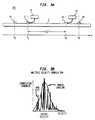
- FIG. 3 shows a conduit 3, along an axis X, transporting a fluid of unknown speed and direction.
- Sensors 21 and 22 are attached to the conduit at locations x1 and x2, respectively. separated by a known distance D12.
- a transducer 41 located at any position, xa, less than or equal to x1 impresses a vibration upon the conduit.
- the transmitted components of the vibration are sensed and recorded at positions x1 and x2 in a manner described above.
- the process is repeated whereby a second transducer 42 located at any position, xb, equal to or greater than x2 impresses a vibration whose components are sensed and recorded at x1 and x2.
- the functions of the transducers at xa and xb may be performed by a simple hammer blow.
- the center velocities of propagation in each direction are computed by cross-correlation and envelope smoothing, as before.
- the sound will propagate in the same direction as the flow; while in the other case it will propagate in a direction opposing the flow.
- the flow rate is half of the difference between the two velocities and the direction of flow corresponds to the faster velocity.
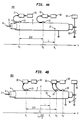
- Power conduit 2 has a jacket 4 which surrounds dielectric 6 which surrounds conductor 8.
- the dielectric may be a solid or a fluid.
- Power conduit 2 contains a defect 10 which may be a leak through jacket 4 for the case of a fluid dielectric, or an electrical leakage path through the dielectric if it is a solid.
- the conduit is considered to lie along an axis X.
- a first sensor 21 is mounted to the conduit at location x1, and a second sensor is mounted to the conduit at location x2.
- the sensors are separated by a distance D12.
- Defect 10 is located outside the span of the sensors at a distance L from the nearest one.
- a first recorder 31 is connected to first sensor 21, and a second recorder 32 is connected to sensor 22.
- a pulse generator 50 is connected to conductor 8. One end of the pulse generator and the jacket are electrically grounded.
- Commercial FM receivers 61 and 62 provide synchronization signals to the recorders coincident with a pulse from generator 50 via transmitter 63.
- arcing is induced at the defect by a short, high potential pulse propagating along the conduit from the generator.
- This so-called “hi-pot” method is also used to clear shorted capacitors.
- the pulse travels at much higher velocity than sound waves generated at the defect, so it may be regarded as instantaneous all along the line and may be used to synchronize the data gathering process.
- the transmitted acoustic energy liberated by the electric discharge is detected with the two sensors and recorded.
- An envelope of a cross-correlation function is computed to obtain t1-t2, the time the acoustic energy takes to propagate the distance D12.
- the velocity of propagation is determined from the time and distance.
- the sign of the quantity (t1-t2) indicates on which side of the sensors the defect is located.
- apparatus 401 which is similar to apparatus 400 except that the defect 10 is located between sensors 21 and 22, and sensor 23 has been mounted at x3.
- the procedure to locate the defect is the same as that given in the discussion for apparatus 200 in FIG. 2.
- Some advantages over the use of surface detection methods are: the ability to better locate a leak in a buried conduit to protect the environment and to reduce the cost and disruption of excavation; the ability to locate leaks in a noisy environments which are typical in cities, and to reject uninteresting sources of noise which include turbulent flow within the conduit, discontinuities in the conduit such as joints and traps, or noise generated by adjacent conduits; increasing the distance over which a leak may be found; the ability to determine the direction and flow rate of a medium within a conduit in a non-intrusive manner; and the ability to locate a defect in an electrical transmission line. For the electrical line, the number of "hi-pot" attempts needed to locate the defect is greatly reduced, thereby minimizing the potential for destroying good dielectric by over-stressing it.
- the apparatus and method described for determining the direction and flow rate of a medium may be incorporated with the embodiment for locating a leak.
- the spectrum of frequencies which are used in the cross-correlation operation may be selected for each combination of conduit and medium to maximize leak noise data and to discriminate against unwanted frequencies.
- Sensors may be connected directly into a computer wherein processes such as, but not limited to: filtering, digital conversion, signal processing, smoothing, synchronization, and the calculations of flow rate, direction, and defect location are performed.
Landscapes
- Physics & Mathematics (AREA)
- General Physics & Mathematics (AREA)
- Examining Or Testing Airtightness (AREA)
- Investigating Or Analyzing Materials By The Use Of Ultrasonic Waves (AREA)
Applications Claiming Priority (2)
| Application Number | Priority Date | Filing Date | Title |
|---|---|---|---|
| US08/336,452 US5531099A (en) | 1994-11-09 | 1994-11-09 | Underground conduit defect localization |
| US336452 | 1994-11-09 |
Publications (2)
| Publication Number | Publication Date |
|---|---|
| EP0711986A2 true EP0711986A2 (de) | 1996-05-15 |
| EP0711986A3 EP0711986A3 (de) | 1998-09-09 |
Family
ID=23316156
Family Applications (1)
| Application Number | Title | Priority Date | Filing Date |
|---|---|---|---|
| EP95307807A Withdrawn EP0711986A3 (de) | 1994-11-09 | 1995-11-01 | Fehlerortung in einer unterirdischen Leitung |
Country Status (4)
| Country | Link |
|---|---|
| US (1) | US5531099A (de) |
| EP (1) | EP0711986A3 (de) |
| JP (1) | JPH08226865A (de) |
| CA (1) | CA2158669C (de) |
Cited By (16)
| Publication number | Priority date | Publication date | Assignee | Title |
|---|---|---|---|---|
| EP0831316A3 (de) * | 1996-09-20 | 1999-02-17 | Palmer Environmental Limited | Korrelatorvorrichtung für Leckgeräusche |
| WO2001051904A3 (en) * | 2000-01-14 | 2001-11-29 | Ca Nat Research Council | Pc multimedia-based leak detection system for water transmission and distribution pipes |
| RU2186356C2 (ru) * | 2000-07-27 | 2002-07-27 | Государственное унитарное предприятие Центральный аэрогидродинамический институт им. профессора Н.Е.Жуковского | Способ измерения звукового давления течи исследуемого объекта и устройство для его осуществления |
| GB2378756A (en) * | 2001-07-16 | 2003-02-19 | Thames Water Utilities | Apparatus for detecting leaks in or determing the nature of a pipe. |
| US8717183B2 (en) | 2009-08-19 | 2014-05-06 | Severn Trent Water Limited | Leak detector |
| US9772250B2 (en) | 2011-08-12 | 2017-09-26 | Mueller International, Llc | Leak detector and sensor |
| US9849322B2 (en) | 2010-06-16 | 2017-12-26 | Mueller International, Llc | Infrastructure monitoring devices, systems, and methods |
| US10283857B2 (en) | 2016-02-12 | 2019-05-07 | Mueller International, Llc | Nozzle cap multi-band antenna assembly |
| US10305178B2 (en) | 2016-02-12 | 2019-05-28 | Mueller International, Llc | Nozzle cap multi-band antenna assembly |
| US10539480B2 (en) | 2017-10-27 | 2020-01-21 | Mueller International, Llc | Frequency sub-band leak detection |
| US10859462B2 (en) | 2018-09-04 | 2020-12-08 | Mueller International, Llc | Hydrant cap leak detector with oriented sensor |
| US11342656B2 (en) | 2018-12-28 | 2022-05-24 | Mueller International, Llc | Nozzle cap encapsulated antenna system |
| US11473993B2 (en) | 2019-05-31 | 2022-10-18 | Mueller International, Llc | Hydrant nozzle cap |
| US11542690B2 (en) | 2020-05-14 | 2023-01-03 | Mueller International, Llc | Hydrant nozzle cap adapter |
| EP3198267B1 (de) * | 2014-09-24 | 2024-08-28 | Rosemount Inc. | Akustische detektion in prozessumgebungen |
| US12578245B2 (en) | 2022-10-28 | 2026-03-17 | Mueller International, Llc | Self-leveling sensor assembly |
Families Citing this family (39)
| Publication number | Priority date | Publication date | Assignee | Title |
|---|---|---|---|---|
| US5974862A (en) * | 1997-05-06 | 1999-11-02 | Flow Metrix, Inc. | Method for detecting leaks in pipelines |
| US6138512A (en) * | 1997-07-30 | 2000-10-31 | Iowa State University Research Foundation, Inc. | Method and apparatus for determining source location of energy carried in the form of propagating waves through a conducting medium |
| JP3639145B2 (ja) * | 1999-02-01 | 2005-04-20 | 三菱電機株式会社 | 異常箇所検出装置 |
| US6389881B1 (en) * | 1999-05-27 | 2002-05-21 | Acoustic Systems, Inc. | Method and apparatus for pattern match filtering for real time acoustic pipeline leak detection and location |
| US20030204338A1 (en) * | 2002-04-22 | 2003-10-30 | Peter Martinek | Method and measurement probe for the performance of measurements in water supply systems |
| US7007545B1 (en) | 1999-10-26 | 2006-03-07 | Peter Martinek | Method and measurement probe for the performance of measurements in water supply systems |
| US6567006B1 (en) | 1999-11-19 | 2003-05-20 | Flow Metrix, Inc. | Monitoring vibrations in a pipeline network |
| GB2358246A (en) * | 2000-01-05 | 2001-07-18 | Palmer Environmental Ltd | Determining the position of a signal from a pipe |
| US6561032B1 (en) | 2000-05-15 | 2003-05-13 | National Research Council Of Canada | Non-destructive measurement of pipe wall thickness |
| US6530263B1 (en) * | 2000-09-29 | 2003-03-11 | Radcom Technologies Ltd | Method and system for localizing and correlating leaks in fluid conveying conduits |
| US6925399B2 (en) * | 2001-03-30 | 2005-08-02 | Verizon Laboratories Inc. | Methods and systems for the estimation of the injection point of foreign signals in a network |
| US6957157B2 (en) | 2002-11-12 | 2005-10-18 | Flow Metrix, Inc. | Tracking vibrations in a pipeline network |
| US7891246B2 (en) * | 2002-11-12 | 2011-02-22 | Itron, Inc. | Tracking vibrations in a pipeline network |
| US6725705B1 (en) | 2003-05-15 | 2004-04-27 | Gas Technology Institute | Enhanced acoustic detection of gas leaks in underground gas pipelines |
| US6999881B2 (en) * | 2003-12-17 | 2006-02-14 | Metravib R.D.S. | Method and apparatus for detecting and locating noise sources whether correlated or not |
| US7328618B2 (en) * | 2005-06-21 | 2008-02-12 | National Research Council Of Canada | Non-destructive testing of pipes |
| WO2009061912A2 (en) * | 2007-11-06 | 2009-05-14 | Purdue Research Foundation | Leak localization in a cavitated body |
| US8555722B2 (en) * | 2009-09-17 | 2013-10-15 | Gas Technology Institute | Method and apparatus for underground line crossing detection |
| US9157878B2 (en) * | 2011-10-13 | 2015-10-13 | Thermal Wave Imaging, Inc. | System and method for detecting aberrations in a conduit |
| SG11201503041SA (en) | 2012-10-26 | 2015-05-28 | Mueller Int Llc | Detecting leaks in a fluid distribution system |
| GB2534750A (en) * | 2013-11-12 | 2016-08-03 | Nec Corp | Leakage determination system and leakage determination method |
| JP6316131B2 (ja) * | 2014-07-18 | 2018-04-25 | 積水化学工業株式会社 | 異常音発生位置の特定方法 |
| US9528903B2 (en) | 2014-10-01 | 2016-12-27 | Mueller International, Llc | Piezoelectric vibration sensor for fluid leak detection |
| JP6557576B2 (ja) * | 2014-11-14 | 2019-08-07 | 積水化学工業株式会社 | 異常音の発生位置特定方法および異常音の発生位置特定装置 |
| US10845460B2 (en) | 2015-06-23 | 2020-11-24 | Nec Corporation | Sound source position detection device, sound source position detection method, sound source position detection program, and recording medium |
| JP2017083291A (ja) * | 2015-10-28 | 2017-05-18 | 積水化学工業株式会社 | 異常音の発生位置特定方法および異常音の発生位置特定装置 |
| US10565752B2 (en) | 2017-04-21 | 2020-02-18 | Mueller International, Llc | Graphical mapping of pipe node location selection |
| US10690630B2 (en) | 2017-04-21 | 2020-06-23 | Mueller International, Llc | Generation and utilization of pipe-specific sound attenuation |
| US10209225B2 (en) * | 2017-04-21 | 2019-02-19 | Mueller International, Llc | Sound propagation comparison with automated frequency selection for pipe condition assessment |
| US10948132B2 (en) | 2017-05-08 | 2021-03-16 | 64Seconds, Inc. | Integrity assessment of a pipeline network |
| US10344446B2 (en) | 2017-10-02 | 2019-07-09 | Consolidated Edison Company Of New York, Inc. | System and method of monitoring a utility structure |
| JP2020101394A (ja) * | 2018-12-20 | 2020-07-02 | 日本電気株式会社 | 漏洩検出システム及び漏洩検出方法 |
| US10768146B1 (en) | 2019-10-21 | 2020-09-08 | Mueller International, Llc | Predicting severity of buildup within pipes using evaluation of residual attenuation |
| US11726064B2 (en) | 2020-07-22 | 2023-08-15 | Mueller International Llc | Acoustic pipe condition assessment using coherent averaging |
| WO2022097066A1 (en) * | 2020-11-05 | 2022-05-12 | Aquarius Spectrum Ltd. | System and method for detecting leaks and location thereof in pipes using multi-spectral correlations |
| US11609348B2 (en) | 2020-12-29 | 2023-03-21 | Mueller International, Llc | High-resolution acoustic pipe condition assessment using in-bracket pipe excitation |
| US12196714B2 (en) | 2021-07-19 | 2025-01-14 | Mueller International, Llc | Acoustic pipeline condition assessment at resolution down to pipe stick |
| CN115575044B (zh) * | 2022-12-08 | 2023-06-13 | 浙江和达科技股份有限公司 | 一种管道节点的渗漏定位方法及智能消火栓 |
| CN118168619A (zh) * | 2024-03-19 | 2024-06-11 | 中国华能集团清洁能源技术研究院有限公司 | 管内流体流量测量方法及装置、电子设备、存储介质 |
Family Cites Families (17)
| Publication number | Priority date | Publication date | Assignee | Title |
|---|---|---|---|---|
| US3626750A (en) * | 1970-01-09 | 1971-12-14 | Us Water Conservation Corp | Leak detection in underground water system |
| US3903729A (en) * | 1970-12-30 | 1975-09-09 | Taft Broadcasting Corp | Method and apparatus for detecting a break or other occurrence in a pipeline containing gas under pressure |
| US3930556A (en) * | 1971-04-26 | 1976-01-06 | Osaka Gas Kabushiki Kaisha | Method of detecting leak of fluid from a long pipeline |
| US4019038A (en) * | 1971-06-10 | 1977-04-19 | Kent Instruments Limited | Correlators |
| US4289019A (en) * | 1979-10-30 | 1981-09-15 | The United States Of America As Represented By The United States Department Of Energy | Method and means of passive detection of leaks in buried pipes |
| US4327576A (en) * | 1980-05-05 | 1982-05-04 | The United States Of America As Represented By The Secretary Of The Navy | Acoustic leak detector |
| JPS58168934A (ja) * | 1982-03-31 | 1983-10-05 | Hitachi Ltd | 流体の漏洩検出方法とその装置 |
| US4858462A (en) * | 1989-01-20 | 1989-08-22 | The Babcock & Wilcox Company | Acoustic emission leak source location |
| US5038614A (en) * | 1989-08-10 | 1991-08-13 | Atlantic Richfield Company | Acoustic vibration detection of fluid leakage from conduits |
| JP2878804B2 (ja) * | 1989-09-19 | 1999-04-05 | 東京瓦斯株式会社 | 配管の異常監視装置 |
| US5117676A (en) * | 1991-02-25 | 1992-06-02 | Hughes Aircraft Company | Leak detector for natural gas pipelines |
| FI87493C (fi) * | 1991-12-23 | 1993-01-11 | Kytoelae Instrumenttitehdas | Foerfarande och anordning foer maetning av stroemningshastigheten av gaser och/eller storheter som kan haerledas fraon denna |
| EP0552044B1 (de) * | 1992-01-16 | 1996-10-09 | Kabushiki Kaisha Toshiba | Verfahren und Vorrichtung zur Positionserkennung einer anormalen Stelle einer erdverlegten Rohrleitung |
| FI88208C (fi) * | 1992-04-01 | 1993-04-13 | Valtion Teknillinen | Foerfarande och anordning foer akustisk maetning av en gasstroem |
| US5361636A (en) * | 1992-09-23 | 1994-11-08 | Columbia Gas Of Ohio, Inc. | Apparatus and process for measuring the magnitude of leaks |
| US5398542A (en) * | 1992-10-16 | 1995-03-21 | Nkk Corporation | Method for determining direction of travel of a wave front and apparatus therefor |
| JPH06201591A (ja) * | 1992-12-28 | 1994-07-19 | Mitsui Mining & Smelting Co Ltd | 圧電性結晶素子の極性判別方法 |
-
1994
- 1994-11-09 US US08/336,452 patent/US5531099A/en not_active Expired - Lifetime
-
1995
- 1995-09-20 CA CA002158669A patent/CA2158669C/en not_active Expired - Lifetime
- 1995-11-01 EP EP95307807A patent/EP0711986A3/de not_active Withdrawn
- 1995-11-08 JP JP7313696A patent/JPH08226865A/ja active Pending
Cited By (37)
| Publication number | Priority date | Publication date | Assignee | Title |
|---|---|---|---|---|
| EP0831316A3 (de) * | 1996-09-20 | 1999-02-17 | Palmer Environmental Limited | Korrelatorvorrichtung für Leckgeräusche |
| US5922942A (en) * | 1996-09-20 | 1999-07-13 | Palmer Environmental Limited | Leak noise correlator apparatus |
| WO2001051904A3 (en) * | 2000-01-14 | 2001-11-29 | Ca Nat Research Council | Pc multimedia-based leak detection system for water transmission and distribution pipes |
| US6453247B1 (en) | 2000-01-14 | 2002-09-17 | National Research Council Of Canada | PC multimedia-based leak detection system for water transmission and distribution pipes |
| RU2186356C2 (ru) * | 2000-07-27 | 2002-07-27 | Государственное унитарное предприятие Центральный аэрогидродинамический институт им. профессора Н.Е.Жуковского | Способ измерения звукового давления течи исследуемого объекта и устройство для его осуществления |
| GB2378756A (en) * | 2001-07-16 | 2003-02-19 | Thames Water Utilities | Apparatus for detecting leaks in or determing the nature of a pipe. |
| US8717183B2 (en) | 2009-08-19 | 2014-05-06 | Severn Trent Water Limited | Leak detector |
| US9849322B2 (en) | 2010-06-16 | 2017-12-26 | Mueller International, Llc | Infrastructure monitoring devices, systems, and methods |
| US9861848B2 (en) | 2010-06-16 | 2018-01-09 | Mueller International, Llc | Infrastructure monitoring devices, systems, and methods |
| US12539437B2 (en) | 2010-06-16 | 2026-02-03 | Mueller International, Llc | Infrastructure monitoring devices, systems, and methods |
| US10857403B2 (en) | 2010-06-16 | 2020-12-08 | Mueller International, Llc | Infrastructure monitoring devices, systems, and methods |
| US10881888B2 (en) | 2010-06-16 | 2021-01-05 | Mueller International, Llc | Infrastructure monitoring devices, systems, and methods |
| US9772250B2 (en) | 2011-08-12 | 2017-09-26 | Mueller International, Llc | Leak detector and sensor |
| US10175135B2 (en) | 2011-08-12 | 2019-01-08 | Mueller International, Llc | Leak detector |
| US10386257B2 (en) | 2011-08-12 | 2019-08-20 | Mueller International, Llc | Enclosure for leak detector |
| US11680865B2 (en) | 2011-08-12 | 2023-06-20 | Mueller International, Llc | Leak detection in water distribution systems using acoustic signals |
| US11630021B2 (en) | 2011-08-12 | 2023-04-18 | Mueller International, Llc | Enclosure for leak detector |
| EP3198267B1 (de) * | 2014-09-24 | 2024-08-28 | Rosemount Inc. | Akustische detektion in prozessumgebungen |
| US11336004B2 (en) | 2016-02-12 | 2022-05-17 | Mueller International, Llc | Nozzle cap multi-band antenna assembly |
| US11652284B2 (en) | 2016-02-12 | 2023-05-16 | Mueller International, Llc | Nozzle cap assembly |
| US10283857B2 (en) | 2016-02-12 | 2019-05-07 | Mueller International, Llc | Nozzle cap multi-band antenna assembly |
| US11469494B2 (en) | 2016-02-12 | 2022-10-11 | Mueller International, Llc | Nozzle cap multi-band antenna assembly |
| US12212053B2 (en) | 2016-02-12 | 2025-01-28 | Mueller International, Llc | Nozzle cap multi-band antenna assembly |
| US11527821B2 (en) | 2016-02-12 | 2022-12-13 | Mueller International, Llc | Nozzle cap assembly |
| US10305178B2 (en) | 2016-02-12 | 2019-05-28 | Mueller International, Llc | Nozzle cap multi-band antenna assembly |
| US11837782B2 (en) | 2016-02-12 | 2023-12-05 | Mueller International, Llc | Nozzle cap assembly |
| US10539480B2 (en) | 2017-10-27 | 2020-01-21 | Mueller International, Llc | Frequency sub-band leak detection |
| US10859462B2 (en) | 2018-09-04 | 2020-12-08 | Mueller International, Llc | Hydrant cap leak detector with oriented sensor |
| US11692901B2 (en) | 2018-09-04 | 2023-07-04 | Mueller International, Llc | Hydrant cap leak detector with oriented sensor |
| US11422054B2 (en) | 2018-09-04 | 2022-08-23 | Mueller International, Llc | Hydrant cap leak detector with oriented sensor |
| US11342656B2 (en) | 2018-12-28 | 2022-05-24 | Mueller International, Llc | Nozzle cap encapsulated antenna system |
| US12489202B2 (en) | 2018-12-28 | 2025-12-02 | Mueller International, Llc | Nozzle cap encapsulated antenna system |
| US11624674B2 (en) | 2019-05-31 | 2023-04-11 | Mueller International, Llc | Hydrant nozzle cap with antenna |
| US12078572B2 (en) | 2019-05-31 | 2024-09-03 | Mueller International, Llc | Hydrant nozzle cap |
| US11473993B2 (en) | 2019-05-31 | 2022-10-18 | Mueller International, Llc | Hydrant nozzle cap |
| US11542690B2 (en) | 2020-05-14 | 2023-01-03 | Mueller International, Llc | Hydrant nozzle cap adapter |
| US12578245B2 (en) | 2022-10-28 | 2026-03-17 | Mueller International, Llc | Self-leveling sensor assembly |
Also Published As
| Publication number | Publication date |
|---|---|
| US5531099A (en) | 1996-07-02 |
| JPH08226865A (ja) | 1996-09-03 |
| CA2158669C (en) | 2000-10-17 |
| CA2158669A1 (en) | 1996-05-10 |
| EP0711986A3 (de) | 1998-09-09 |
Similar Documents
| Publication | Publication Date | Title |
|---|---|---|
| US5531099A (en) | Underground conduit defect localization | |
| US4289019A (en) | Method and means of passive detection of leaks in buried pipes | |
| JP2878804B2 (ja) | 配管の異常監視装置 | |
| US6389881B1 (en) | Method and apparatus for pattern match filtering for real time acoustic pipeline leak detection and location | |
| EP0418224B1 (de) | Ultraschallumsetzer zur messung der strömungsgeschwindigkeit einer flüssigkeit in einem rohr | |
| US5058419A (en) | Method and apparatus for determining the location of a sound source | |
| US6453247B1 (en) | PC multimedia-based leak detection system for water transmission and distribution pipes | |
| US4327576A (en) | Acoustic leak detector | |
| KR101876730B1 (ko) | 상수도 누수탐지 감시 시스템 | |
| US4435974A (en) | Method and apparatus for locating leakages in pipes and similar conduits | |
| US5623421A (en) | Monitoring pressurized vessels for leaks, ruptures or hard hits | |
| EP1177413A1 (de) | Aufsteckbarer gas-durchflussmesser | |
| CA2101652C (en) | Measurement of the flow velocities of gases and/or of quantities that can be derived from same | |
| CN110469782B (zh) | 一种基于自适应滤波器的管道泄漏定位装置 | |
| KR101956160B1 (ko) | 누수 탐지 장치 | |
| JPH08508808A (ja) | 導管網中の漏れ箇所の特定装置および方法 | |
| US5412989A (en) | Acoustic tracing of buried conduits | |
| JP4074154B2 (ja) | 配管破損探査装置 | |
| JPH11201858A (ja) | 相関法を用いる管路系の振動測定方法 | |
| RU2196312C2 (ru) | Устройство поиска мест утечек магистральных трубопроводов | |
| KR920007634B1 (ko) | 누수위치 추정장치 및 방법 | |
| US20200024940A1 (en) | Resonant acoustic structure for measuring well or borehole depth | |
| JPH1164152A (ja) | ガス配管の漏洩位置標定方法および装置 | |
| US4372151A (en) | Automatic fault locating apparatus for a pressurized pipeline | |
| CA2292009C (en) | Underground conduit defect localization |
Legal Events
| Date | Code | Title | Description |
|---|---|---|---|
| PUAI | Public reference made under article 153(3) epc to a published international application that has entered the european phase |
Free format text: ORIGINAL CODE: 0009012 |
|
| AK | Designated contracting states |
Kind code of ref document: A2 Designated state(s): DE FR GB |
|
| PUAL | Search report despatched |
Free format text: ORIGINAL CODE: 0009013 |
|
| AK | Designated contracting states |
Kind code of ref document: A3 Designated state(s): DE FR GB |
|
| 17P | Request for examination filed |
Effective date: 19990225 |
|
| 17Q | First examination report despatched |
Effective date: 20010924 |
|
| STAA | Information on the status of an ep patent application or granted ep patent |
Free format text: STATUS: THE APPLICATION IS DEEMED TO BE WITHDRAWN |
|
| 18D | Application deemed to be withdrawn |
Effective date: 20030215 |