EP0712217A2 - Faseroptischer Verstärker mit Polarisationsbegrenzungsmitteln - Google Patents
Faseroptischer Verstärker mit Polarisationsbegrenzungsmitteln Download PDFInfo
- Publication number
- EP0712217A2 EP0712217A2 EP95120727A EP95120727A EP0712217A2 EP 0712217 A2 EP0712217 A2 EP 0712217A2 EP 95120727 A EP95120727 A EP 95120727A EP 95120727 A EP95120727 A EP 95120727A EP 0712217 A2 EP0712217 A2 EP 0712217A2
- Authority
- EP
- European Patent Office
- Prior art keywords
- light
- polarization
- signal
- optical
- fiber amplifier
- Prior art date
- Legal status (The legal status is an assumption and is not a legal conclusion. Google has not performed a legal analysis and makes no representation as to the accuracy of the status listed.)
- Withdrawn
Links
Images



Classifications
-
- H—ELECTRICITY
- H04—ELECTRIC COMMUNICATION TECHNIQUE
- H04B—TRANSMISSION
- H04B10/00—Transmission systems employing electromagnetic waves other than radio-waves, e.g. infrared, visible or ultraviolet light, or employing corpuscular radiation, e.g. quantum communication
- H04B10/60—Receivers
- H04B10/66—Non-coherent receivers, e.g. using direct detection
-
- H—ELECTRICITY
- H01—ELECTRIC ELEMENTS
- H01S—DEVICES USING THE PROCESS OF LIGHT AMPLIFICATION BY STIMULATED EMISSION OF RADIATION [LASER] TO AMPLIFY OR GENERATE LIGHT; DEVICES USING STIMULATED EMISSION OF ELECTROMAGNETIC RADIATION IN WAVE RANGES OTHER THAN OPTICAL
- H01S3/00—Lasers, i.e. devices using stimulated emission of electromagnetic radiation in the infrared, visible or ultraviolet wave range
- H01S3/09—Processes or apparatus for excitation, e.g. pumping
- H01S3/091—Processes or apparatus for excitation, e.g. pumping using optical pumping
- H01S3/094—Processes or apparatus for excitation, e.g. pumping using optical pumping by coherent light
- H01S3/094003—Processes or apparatus for excitation, e.g. pumping using optical pumping by coherent light the pumped medium being a fibre
-
- H—ELECTRICITY
- H01—ELECTRIC ELEMENTS
- H01S—DEVICES USING THE PROCESS OF LIGHT AMPLIFICATION BY STIMULATED EMISSION OF RADIATION [LASER] TO AMPLIFY OR GENERATE LIGHT; DEVICES USING STIMULATED EMISSION OF ELECTROMAGNETIC RADIATION IN WAVE RANGES OTHER THAN OPTICAL
- H01S3/00—Lasers, i.e. devices using stimulated emission of electromagnetic radiation in the infrared, visible or ultraviolet wave range
- H01S3/10—Controlling the intensity, frequency, phase, polarisation or direction of the emitted radiation, e.g. switching, gating, modulating or demodulating
- H01S3/13—Stabilisation of laser output parameters, e.g. frequency or amplitude
- H01S3/1301—Stabilisation of laser output parameters, e.g. frequency or amplitude in optical amplifiers
- H01S3/13013—Stabilisation of laser output parameters, e.g. frequency or amplitude in optical amplifiers by controlling the optical pumping
-
- H—ELECTRICITY
- H04—ELECTRIC COMMUNICATION TECHNIQUE
- H04B—TRANSMISSION
- H04B10/00—Transmission systems employing electromagnetic waves other than radio-waves, e.g. infrared, visible or ultraviolet light, or employing corpuscular radiation, e.g. quantum communication
- H04B10/29—Repeaters
- H04B10/291—Repeaters in which processing or amplification is carried out without conversion of the main signal from optical form
- H04B10/293—Signal power control
- H04B10/2933—Signal power control considering the whole optical path
- H04B10/2935—Signal power control considering the whole optical path with a cascade of amplifiers
-
- H—ELECTRICITY
- H04—ELECTRIC COMMUNICATION TECHNIQUE
- H04B—TRANSMISSION
- H04B10/00—Transmission systems employing electromagnetic waves other than radio-waves, e.g. infrared, visible or ultraviolet light, or employing corpuscular radiation, e.g. quantum communication
- H04B10/50—Transmitters
- H04B10/501—Structural aspects
- H04B10/503—Laser transmitters
-
- H—ELECTRICITY
- H01—ELECTRIC ELEMENTS
- H01S—DEVICES USING THE PROCESS OF LIGHT AMPLIFICATION BY STIMULATED EMISSION OF RADIATION [LASER] TO AMPLIFY OR GENERATE LIGHT; DEVICES USING STIMULATED EMISSION OF ELECTROMAGNETIC RADIATION IN WAVE RANGES OTHER THAN OPTICAL
- H01S3/00—Lasers, i.e. devices using stimulated emission of electromagnetic radiation in the infrared, visible or ultraviolet wave range
- H01S3/05—Construction or shape of optical resonators; Accommodation of active medium therein; Shape of active medium
- H01S3/06—Construction or shape of active medium
- H01S3/063—Waveguide lasers, i.e. whereby the dimensions of the waveguide are of the order of the light wavelength
- H01S3/067—Fibre lasers
- H01S3/06754—Fibre amplifiers
-
- H—ELECTRICITY
- H01—ELECTRIC ELEMENTS
- H01S—DEVICES USING THE PROCESS OF LIGHT AMPLIFICATION BY STIMULATED EMISSION OF RADIATION [LASER] TO AMPLIFY OR GENERATE LIGHT; DEVICES USING STIMULATED EMISSION OF ELECTROMAGNETIC RADIATION IN WAVE RANGES OTHER THAN OPTICAL
- H01S3/00—Lasers, i.e. devices using stimulated emission of electromagnetic radiation in the infrared, visible or ultraviolet wave range
- H01S3/09—Processes or apparatus for excitation, e.g. pumping
- H01S3/091—Processes or apparatus for excitation, e.g. pumping using optical pumping
- H01S3/094—Processes or apparatus for excitation, e.g. pumping using optical pumping by coherent light
- H01S3/094003—Processes or apparatus for excitation, e.g. pumping using optical pumping by coherent light the pumped medium being a fibre
- H01S3/094011—Processes or apparatus for excitation, e.g. pumping using optical pumping by coherent light the pumped medium being a fibre with bidirectional pumping, i.e. with injection of the pump light from both two ends of the fibre
-
- H—ELECTRICITY
- H01—ELECTRIC ELEMENTS
- H01S—DEVICES USING THE PROCESS OF LIGHT AMPLIFICATION BY STIMULATED EMISSION OF RADIATION [LASER] TO AMPLIFY OR GENERATE LIGHT; DEVICES USING STIMULATED EMISSION OF ELECTROMAGNETIC RADIATION IN WAVE RANGES OTHER THAN OPTICAL
- H01S3/00—Lasers, i.e. devices using stimulated emission of electromagnetic radiation in the infrared, visible or ultraviolet wave range
- H01S3/09—Processes or apparatus for excitation, e.g. pumping
- H01S3/091—Processes or apparatus for excitation, e.g. pumping using optical pumping
- H01S3/094—Processes or apparatus for excitation, e.g. pumping using optical pumping by coherent light
- H01S3/09408—Pump redundancy
-
- H—ELECTRICITY
- H01—ELECTRIC ELEMENTS
- H01S—DEVICES USING THE PROCESS OF LIGHT AMPLIFICATION BY STIMULATED EMISSION OF RADIATION [LASER] TO AMPLIFY OR GENERATE LIGHT; DEVICES USING STIMULATED EMISSION OF ELECTROMAGNETIC RADIATION IN WAVE RANGES OTHER THAN OPTICAL
- H01S3/00—Lasers, i.e. devices using stimulated emission of electromagnetic radiation in the infrared, visible or ultraviolet wave range
- H01S3/09—Processes or apparatus for excitation, e.g. pumping
- H01S3/091—Processes or apparatus for excitation, e.g. pumping using optical pumping
- H01S3/094—Processes or apparatus for excitation, e.g. pumping using optical pumping by coherent light
- H01S3/094096—Multi-wavelength pumping
-
- H—ELECTRICITY
- H01—ELECTRIC ELEMENTS
- H01S—DEVICES USING THE PROCESS OF LIGHT AMPLIFICATION BY STIMULATED EMISSION OF RADIATION [LASER] TO AMPLIFY OR GENERATE LIGHT; DEVICES USING STIMULATED EMISSION OF ELECTROMAGNETIC RADIATION IN WAVE RANGES OTHER THAN OPTICAL
- H01S3/00—Lasers, i.e. devices using stimulated emission of electromagnetic radiation in the infrared, visible or ultraviolet wave range
- H01S3/23—Arrangements of two or more lasers not provided for in groups H01S3/02 - H01S3/22, e.g. tandem arrangements of separate active media
- H01S3/2383—Parallel arrangements
-
- H—ELECTRICITY
- H04—ELECTRIC COMMUNICATION TECHNIQUE
- H04B—TRANSMISSION
- H04B2210/00—Indexing scheme relating to optical transmission systems
- H04B2210/003—Devices including multiple stages, e.g., multi-stage optical amplifiers or dispersion compensators
Definitions
- This invention relates to an optical-fiber amplifier which is to be used in a light communication system and uses an optical fiber doped of a rare earth element.
- FIG. 1 shows conventional light amplifier, which is disclosed in "The Impact That An Er-doped Optical-Fiber Amplifier Contributes To Light Communication" by T. Shimada, O plus E, No. 113, pp. 75-82, 1989.
- reference numeral 1 designates a rare-earth-doped optical fiber; 2, an pumping light source; 3, a combining and dividing device; 4, an pumping light source drive circuit; and 5, an optical fiber serving as a signal transmission path.
- the rare-earth-doped optical fiber 1 is a single-mode optical fiber doped of a rare earth element such as erbium (ER) and having a length of several meters to several tens meters.
- the combining and dividing device 3a is connected to the rare-earth-doped optical fiber 1.
- the combining and dividing device may be an optical coupler.
- the pumping light source 2 is a semiconductor laser having a wavelength of, for example, 1.48 ⁇ m and is driven the pumping light source drive circuit 4.
- the rare-earth-doped optical fiber 1 assumes an inverted distribution state so that the signal light having a wavelength of 1.53 or 1.55 ⁇ m and inputted from the optical fiber 5 is amplified by the action of induced emission.
- the rare-earth-doped optical fiber 1, the pumping light source 2, the combining and dividing device 3 and the pumping light source drive circuit 4 jointly constitute a light amplifying means.
- spontaneous emission light is emitted along with the action of light amplification.
- This spontaneous emission light produce noice, which deteriorates the signal-to-noise rate of signal light.
- the noice resulting from spontaneous emission light is exemplified by shot noise due to spontaneous emission light, beat noise between signal light and spontaneous emission light, and beat noise between one spontaneous emission light and another natural emission light.
- Spontaneous emission light is free of polarization dependency and has the component parallel to the polarization plane of signal light and that perpendicualr thereto.
- the noise resulting from spontaneous emission light would deteriorate the signal-to-noise ratio of signal light. If two or more of the conventional light amplifiers are used as connected in tandem, accumulation of spontaneous emission light would bring down the saturation level of signal gain of the individual light amplifier.
- Object of the invention spontaneous provide an optical-fiber amplifier which reduces spontaneous emission and can retard deterioration of the signal-to-noise ratio, causing only a limited extent of lowering of saturation level due to the cascade connection.
- an optical-fiber amplifier comprising: light-amplifying means for amplifying a light signal; and polarization-limiting means connected in series to the light-amplifying means for eliminating spontaneous emission light from the light-amplifying means.
- the light-amplifying means may include an optical fiber doped of, for example, a rare earth element.
- the optical-fiber amplifier may further comprise: means for dividing part of the output light from the polarization-limiting means; light-detecting means connected to one output terminal of the dividing means; and means for controlling the polarization-limiting means based on the output of the light detecting means.
- the polarization regulating means eliminates or reduces the spontaneous emission light whose polarization plane is perpendicular to that of the light signal emitted from the light amplifying means to retard deterioration of the signal-to-noise ratio due to the noise of the spontaneous emission light. Further, partly since the output light divided by the dividing means is detected and partly since the polarization plane of the polarization controlling means is controlled based on the detected output light power, it is possible to control the output light power freely.
- the operation of the optical-fiber amplifier of this embodiment will now described.
- the pumping light outputted from the pumping light source 122 is inputted to the rare-earth-doped optical fiber 121, which serves as an amplifying medium, by the pumping light combining and dividing device 123, and the signal light inputted from the optical fiber 125 is amplified.
- the polarization regulator 126 controls the pumping light in such a manner that the light in a polarized state equal to that of the amplified signal light transmits, it is possible to retard deterioration of the signal-to-noise ratio of signal light.
- the solid-line curve in FIG. 7 represents the noise figure of the light amplifier of this invention, showing that the noise figure is lowered in all areas. Since the main noise particularly in the area 1 is beat noise in spontaneous emission light, it is seen that the noise figure is lowered sharply in the area 1.
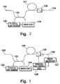
- FIG. 3 is an second embodiment of the optial-fiber amplifier of the invention.
- reference numeral 121 designates an optical fiber doped of a rare earth element; 122, a pumping light source; 123, a combining device for combining signal light and pumping light; 126, a polarization regulator; 129, a dividing device for dividing part of output light; 127, a light detector (also called "light receiver") for measuring the power of the divided signal light; and 128, a control circuit for controlling the polarization regulator 126 in such a manner that the output of the light detector 127 becomes maximal.
- the light detector may be a photodiode, an avalanche photodiode or else.
- the operation of the optical-fiber amplifier will now be described.
- the pumping light outputted from the pumping light source 122 is inputted to the rare-earth-doped optical fiber 11, which serves as an amplifying medium, by the pumping light combining and dividing device 123, and the signal light inputted from the optical fiber 125 is amplified.
- Part of the amplified light signal is divided by the dividing device 129, and its power is measured by he light detector 127.
- the polarization regulator 126 If the polarization regulator 126 is controlled by the control circuit 128 in such a manner that the output of the light detector 127 becomes maximal, the polarization regulator 126 causes the light in a polarized state equal to the polarized state of the amplified signal light to transmit, following the change of the polarized state of the signal light. At that time, since the spontaneous emission light component perpendicular to the polarized state of the signal light, it is possible to retard deterioration of the signal-to-noise ratio of signal light.
- FIG. 4 shows a ninth embodiment of the optical-fiber amplifier of the invention.
- reference numeral 121 designates a polarization-maintaining fiber doped of a rare earth element; 122, an pumping light source; 123, a combining device for combining signal light and pumping light; and 126, a polarization regulator.
- the polarization regulator 126 regulates polarization in such a manner that the polarization plane of the signal light coincides the polarization plane of incidence of the rare-earth-doped polarization-maintaining fiber.
- the operation of the optical-fiber amplifier of this invention will now be described.
- the pumping light outputted from the pumping light source 122 is inputted by the combining and dividing device 123 to the rare-earth-doped optical fiber 121, which serves as an amplifying medium, and the signal light is thereby amplified.
- the polarization regulator 126 regulates polarization in such a manner that the polarization plane of the signal light coincides the polarization plane of incidence of the rare-earth-doped polarization-maintaining fiber. Since the spontaneous emission light component perpendicular to the polarized state of the signal light does not transmit, it is possible to retard deterioration of the signal-to-noise ratio of signal light.
- FIG. 5 shows a third embodiment of the optical-fiber amplifier of the invention.
- reference numeral 121 designates a pumping light source; 123, a combining device for combining signal light and pumping light; 126, a polarization regulator; 129, a dividing device for dividing part of output light; 127, a light detector for measuring the power of the divided signal light; 128, a control circuit; and 131, a output power selector.
- the control circuit 128 controls the polarization regulator 6 based on the output of the output power selector 131 and the output of the light detector 127.
- the pumping light outputted from the pumping light source 122 is inputted to the rare-earth-doped optical fiber 121, which serves as an amplifying medium, by the combining and dividing device 123, and the signal light inputted from the optical fiber 125.
- Part of the amplified light signal is divided by the dividing device 129, and its power is measured by the light detector 127.
- the control circuit 128 controls the polarization regulator 126 in such a manner that the power of the light detector 127 and the power of the output power selector 131 becomes equal to one another.
- control circuit 128 changes the polarized state of the polarization regulator 126, through which the signal light is to be transmitted, so as to regulate fluctuation of level of the output light power, it is possible to output a constant level of power.
- the polarization regulator 126 has a range of control such that the angle between the polarization plane, through which light is to be transmit, and the polarization plane of the signal light ranges from 0 to 45 degrees, the spontaneous emission light component perpendicular to the polarized state of the signal light will be reduced to retard deterioration of signal-to-noise ratio of the signal light.
- FIG. 6 illustrates the operation of the polarization regulator 126, which operates the within the range indicated by the area X, i.e. from 0 to 45 degrees.
- An arrow 51 indicates the case in which the angle between the polarization plane, through which light is to be transmitted, and the polarization plane of the signal light is 0 degree; in this case, the signal light is transmitted, while the spontaneous emission light component (i.e., in the direction indicated by an arrow 53) perpendicular to the signal light is cut off.
- the signal light is transmitted to 1/2 while the spontaneous emission light component is cut off to 1/2. Therefore, assuming that the angle is varied between the arrows 51, 52 (i.e.
- the output of the signal eight can be in the range between 100 % and 50 % while the spontaneous emission light component of the direction indicated by the arrow 53 can be cut off in the range between 100 % and 50 %, improving the signal-to-noise ratio.
- the polarization regulator is preset to operate within the range between 0 and 45 degrees, it is possible to adjust the output of the signal light and, at the same time, to improve the signal-to-noise ratio.
- the polarization regulator is a polarizer.
- the polarization regulator may be an combination of a polarizer and a polarized-state changing means.
- the polarized-state changing means may be a polarization controller composed of a ⁇ /4 plate and a ⁇ /2 plate, may utilize a Faraday rotating device, or may be any other form.
- the light amplifying means is a rare-earth-doped optical fiber.
- the amplifying means may be a semiconductor laser amplifier.
Landscapes
- Physics & Mathematics (AREA)
- Electromagnetism (AREA)
- Engineering & Computer Science (AREA)
- Optics & Photonics (AREA)
- Computer Networks & Wireless Communication (AREA)
- Signal Processing (AREA)
- Plasma & Fusion (AREA)
- Lasers (AREA)
- Optical Communication System (AREA)
Applications Claiming Priority (9)
| Application Number | Priority Date | Filing Date | Title |
|---|---|---|---|
| JP292865/91 | 1991-11-08 | ||
| JP29286591A JP3137391B2 (ja) | 1991-11-08 | 1991-11-08 | ファイバ形光増幅器 |
| JP31846/92 | 1992-02-19 | ||
| JP3184692A JPH05235442A (ja) | 1992-02-19 | 1992-02-19 | 光増幅器 |
| JP85518/92 | 1992-04-07 | ||
| JP8551892A JP3010897B2 (ja) | 1992-04-07 | 1992-04-07 | 光中継装置 |
| JP4162786A JP3008673B2 (ja) | 1992-06-22 | 1992-06-22 | 光増幅中継器の監視方式 |
| JP162786/92 | 1992-06-22 | ||
| EP92118891A EP0541061B1 (de) | 1991-11-08 | 1992-11-04 | Faseroptischer Verstärker |
Related Parent Applications (1)
| Application Number | Title | Priority Date | Filing Date |
|---|---|---|---|
| EP92118891.8 Division | 1992-11-04 |
Publications (2)
| Publication Number | Publication Date |
|---|---|
| EP0712217A2 true EP0712217A2 (de) | 1996-05-15 |
| EP0712217A3 EP0712217A3 (de) | 1996-08-07 |
Family
ID=27459510
Family Applications (5)
| Application Number | Title | Priority Date | Filing Date |
|---|---|---|---|
| EP92118891A Expired - Lifetime EP0541061B1 (de) | 1991-11-08 | 1992-11-04 | Faseroptischer Verstärker |
| EP96118886A Expired - Lifetime EP0768766B1 (de) | 1991-11-08 | 1992-11-04 | Optisches Relaissystem mit Faserverstärkern |
| EP97101954A Expired - Lifetime EP0778682B1 (de) | 1991-11-08 | 1992-11-04 | Optisches Faserverstärkerrelaissystem |
| EP95120727A Withdrawn EP0712217A3 (de) | 1991-11-08 | 1992-11-04 | Faseroptischer Verstärker mit Polarisationsbegrenzungsmitteln |
| EP94116464A Expired - Lifetime EP0652613B1 (de) | 1991-11-08 | 1992-11-04 | Faseroptischer Verstärker |
Family Applications Before (3)
| Application Number | Title | Priority Date | Filing Date |
|---|---|---|---|
| EP92118891A Expired - Lifetime EP0541061B1 (de) | 1991-11-08 | 1992-11-04 | Faseroptischer Verstärker |
| EP96118886A Expired - Lifetime EP0768766B1 (de) | 1991-11-08 | 1992-11-04 | Optisches Relaissystem mit Faserverstärkern |
| EP97101954A Expired - Lifetime EP0778682B1 (de) | 1991-11-08 | 1992-11-04 | Optisches Faserverstärkerrelaissystem |
Family Applications After (1)
| Application Number | Title | Priority Date | Filing Date |
|---|---|---|---|
| EP94116464A Expired - Lifetime EP0652613B1 (de) | 1991-11-08 | 1992-11-04 | Faseroptischer Verstärker |
Country Status (3)
| Country | Link |
|---|---|
| US (1) | US5367587A (de) |
| EP (5) | EP0541061B1 (de) |
| DE (4) | DE69228393T2 (de) |
Families Citing this family (25)
| Publication number | Priority date | Publication date | Assignee | Title |
|---|---|---|---|---|
| GB9217706D0 (en) * | 1992-08-20 | 1992-09-30 | Bt & D Technologies Ltd | Multistage fibre amplifier |
| JPH06318754A (ja) * | 1993-05-10 | 1994-11-15 | Matsushita Electric Ind Co Ltd | 光ファイバ増幅器および光信号伝送システム |
| JP3247919B2 (ja) * | 1993-07-19 | 2002-01-21 | 三菱電機株式会社 | 光増幅装置 |
| GB2280560B (en) * | 1993-07-31 | 1997-09-03 | Northern Telecom Ltd | Communications system |
| JPH07176813A (ja) * | 1993-12-17 | 1995-07-14 | Fujitsu Ltd | 光ファイバ増幅器 |
| DE4409444A1 (de) * | 1994-03-19 | 1995-09-21 | Sel Alcatel Ag | Optisch gepumpter bistabiler Laser |
| JP3250428B2 (ja) * | 1995-09-28 | 2002-01-28 | 三菱電機株式会社 | 光増幅装置 |
| US5808770A (en) * | 1995-12-29 | 1998-09-15 | Lucent Technologies, Inc. | Method and apparatus for using on-off-keying using laser relaxation oscillation |
| JP3730299B2 (ja) * | 1996-02-07 | 2005-12-21 | 富士通株式会社 | 光等化増幅器および光等化増幅方法 |
| CA2172873C (en) * | 1996-03-28 | 2002-03-12 | Kim Byron Roberts | Method of determining optical amplifier failures |
| JPH1012954A (ja) | 1996-06-26 | 1998-01-16 | Fujitsu Ltd | 光増幅器 |
| GB2354367B (en) * | 1996-06-26 | 2001-04-25 | Fujitsu Ltd | Method of and apparatus for controlling an optical amplifier |
| JP3652804B2 (ja) | 1996-09-06 | 2005-05-25 | 富士通株式会社 | 光伝送装置 |
| JP3327148B2 (ja) * | 1996-11-21 | 2002-09-24 | ケイディーディーアイ株式会社 | 光増幅器及びレーザ光発生装置 |
| US6211985B1 (en) * | 1997-08-08 | 2001-04-03 | Tyco Submarine Systems Ltd. | Remote monitoring of an optical transmission system using line monitoring signals |
| US6327077B1 (en) * | 1998-09-29 | 2001-12-04 | Nec Corporation | Optical direct amplifier device and bidirectionally pumped optical direct amplifier device |
| JP2000150992A (ja) * | 1998-11-11 | 2000-05-30 | Nec Corp | 光増幅器 |
| JP2001356377A (ja) * | 2000-06-16 | 2001-12-26 | Kdd Submarine Cable Systems Inc | ポンプ光発生装置及びファイバラマン増幅器 |
| US20030011878A1 (en) * | 2001-07-11 | 2003-01-16 | Maas Steven J. | Remote pumping of optical amplifier system and method |
| US20030081307A1 (en) * | 2001-09-28 | 2003-05-01 | Fludger Christopher R. | Raman amplification |
| US7245423B1 (en) | 2006-07-24 | 2007-07-17 | Itt Manufacturing Enterprises, Inc. | Reducing noise in a fiber amplifier using a cleaning optical signal |
| EP2294729B1 (de) * | 2008-05-21 | 2016-01-06 | Silicon Line GmbH | Schaltungsanordnung und verfahren zum ansteuern lichtemittierender bauelemente zur datenübertragung |
| JP5614327B2 (ja) * | 2011-02-24 | 2014-10-29 | 日本電気株式会社 | 光増幅器制御装置 |
| CN109075857B (zh) | 2016-03-30 | 2021-07-06 | 日本电气株式会社 | 信号回送回路和信号回送方法 |
| EP3817161A4 (de) * | 2018-06-28 | 2021-09-01 | NEC Corporation | Lichtquellenvorrichtung und optischer verstärker |
Family Cites Families (23)
| Publication number | Priority date | Publication date | Assignee | Title |
|---|---|---|---|---|
| DE3167165D1 (en) * | 1980-06-16 | 1984-12-20 | Post Office | Digital transmission systems |
| JPS59101629A (ja) * | 1982-12-01 | 1984-06-12 | Nec Corp | ファイバ内光増幅装置 |
| JPS59200486A (ja) * | 1983-04-27 | 1984-11-13 | Nippon Telegr & Teleph Corp <Ntt> | 光フアイバによる光増幅装置 |
| JPS6035344A (ja) * | 1983-08-08 | 1985-02-23 | Hitachi Tobu Semiconductor Ltd | 発光装置およびこれを用いた光学的信号処理装置 |
| US4554510A (en) * | 1983-09-12 | 1985-11-19 | The Board Of Trustees Of Leland Stanford Junior University | Switching fiber optic amplifier |
| JPS61133688A (ja) * | 1984-12-03 | 1986-06-20 | Fujitsu Ltd | 半導体レ−ザ波長制御装置 |
| JPH0738474B2 (ja) | 1989-03-15 | 1995-04-26 | 国際電信電話株式会社 | ポンピング光用光源の冗長方式 |
| US5005937A (en) * | 1989-04-14 | 1991-04-09 | Nippon Telegraph And Telephone Corporation | Optical branching equipment and optical network using the same |
| CA2019253C (en) * | 1989-06-23 | 1994-01-11 | Shinya Inagaki | Optical fiber amplifier |
| JP3137632B2 (ja) * | 1989-08-31 | 2001-02-26 | 富士通株式会社 | 光ファイバ増幅器を備えた光通信方式 |
| US5058974A (en) * | 1989-10-06 | 1991-10-22 | At&T Bell Laboratories | Distributed amplification for lightwave transmission system |
| JPH03127886A (ja) * | 1989-10-13 | 1991-05-30 | Mitsubishi Cable Ind Ltd | 光増幅器 |
| JPH03215982A (ja) * | 1990-01-19 | 1991-09-20 | Mitsubishi Electric Corp | ファイバ形光増幅器 |
| JP2951985B2 (ja) | 1990-01-19 | 1999-09-20 | 日本電信電話株式会社 | 光中継器の監視信号転送装置 |
| DE4005867A1 (de) * | 1990-02-24 | 1991-08-29 | Standard Elektrik Lorenz Ag | Faseroptischer verstaerker |
| US5015054A (en) * | 1990-02-26 | 1991-05-14 | The United States Of America As Represented By The Department Of Energy | Apparatus and method for increasing the bandwidth of a laser beam |
| JPH0834454B2 (ja) * | 1990-03-01 | 1996-03-29 | 国際電信電話株式会社 | 光中継器の監視方式 |
| CA2037350C (en) * | 1990-03-02 | 1994-11-08 | Kenichi Abe | Optical coupler |
| DE4006867A1 (de) * | 1990-03-05 | 1991-09-12 | Reutlinger & Soehne Gmbh U Co | Vorrichtung zum eindrehen eines wuchtkoerpers in eine bearbeitungsposition |
| US5229876A (en) * | 1990-03-26 | 1993-07-20 | At&T Bell Laboratories | Telemetry for optical fiber amplifier repeater |
| US5115338A (en) * | 1990-05-30 | 1992-05-19 | At&T Bell Laboratories | Multi-stage optical amplifier |
| US5216728A (en) * | 1991-06-14 | 1993-06-01 | Corning Incorporated | Optical fiber amplifier with filter |
| US5187759A (en) * | 1991-11-07 | 1993-02-16 | At&T Bell Laboratories | High gain multi-mode optical amplifier |
-
1992
- 1992-11-04 DE DE69228393T patent/DE69228393T2/de not_active Expired - Fee Related
- 1992-11-04 EP EP92118891A patent/EP0541061B1/de not_active Expired - Lifetime
- 1992-11-04 EP EP96118886A patent/EP0768766B1/de not_active Expired - Lifetime
- 1992-11-04 DE DE69231919T patent/DE69231919T2/de not_active Expired - Lifetime
- 1992-11-04 EP EP97101954A patent/EP0778682B1/de not_active Expired - Lifetime
- 1992-11-04 DE DE69220648T patent/DE69220648T2/de not_active Expired - Fee Related
- 1992-11-04 EP EP95120727A patent/EP0712217A3/de not_active Withdrawn
- 1992-11-04 EP EP94116464A patent/EP0652613B1/de not_active Expired - Lifetime
- 1992-11-04 DE DE69231259T patent/DE69231259T2/de not_active Expired - Lifetime
-
1994
- 1994-02-09 US US08/193,721 patent/US5367587A/en not_active Expired - Lifetime
Also Published As
| Publication number | Publication date |
|---|---|
| EP0541061A3 (de) | 1994-01-12 |
| DE69231259D1 (de) | 2000-08-17 |
| DE69231259T2 (de) | 2001-01-04 |
| DE69231919D1 (de) | 2001-08-09 |
| EP0778682A3 (de) | 1997-10-22 |
| EP0768766B1 (de) | 2001-07-04 |
| EP0652613A3 (de) | 1995-08-16 |
| DE69228393T2 (de) | 1999-06-17 |
| DE69220648D1 (de) | 1997-08-07 |
| DE69228393D1 (de) | 1999-03-18 |
| EP0778682A2 (de) | 1997-06-11 |
| EP0768766A2 (de) | 1997-04-16 |
| DE69231919T2 (de) | 2002-04-04 |
| EP0541061B1 (de) | 1997-07-02 |
| EP0652613B1 (de) | 1999-02-03 |
| EP0541061A2 (de) | 1993-05-12 |
| EP0652613A2 (de) | 1995-05-10 |
| EP0778682B1 (de) | 2000-07-12 |
| EP0768766A3 (de) | 1998-01-21 |
| DE69220648T2 (de) | 1997-12-18 |
| EP0712217A3 (de) | 1996-08-07 |
| US5367587A (en) | 1994-11-22 |
Similar Documents
| Publication | Publication Date | Title |
|---|---|---|
| US5245690A (en) | Optical fiber amplifier including rare earth doped fiber and feedback pump light source control | |
| US6104528A (en) | Optical fiber amplifier for achieving high gain of small signal | |
| JP3757018B2 (ja) | 光増幅装置および光増幅装置の制御方法ならびに光増幅装置を用いた光伝送システム | |
| CA2062216C (en) | Optical-to-electric transducer with extended dynamic range | |
| US6407854B1 (en) | Fiber amplifier with fast transient response and constant gain | |
| EP0541061B1 (de) | Faseroptischer Verstärker | |
| EP1427075A2 (de) | Ramanverstärker und optisches Übertragungssystem | |
| KR20010010768A (ko) | 피드 백 루프를 이용한 장파장 대역 광섬유 증폭기 | |
| US5636054A (en) | Regulated optical amplifier having an optical circulator | |
| JP3368915B2 (ja) | 光増幅器 | |
| KR100334789B1 (ko) | 피드 백 루프를 이용한 광학 소자 측정용 광대역 광원 | |
| EP0570941B1 (de) | Faseroptischer Verstärker | |
| EP1480305B1 (de) | Optisches Halbleiterverstärker-Modul | |
| RU2192081C2 (ru) | Длиннополосный волоконно-оптический лазерный усилитель, использующий затравочный пучок | |
| US7440171B2 (en) | Staged amplifier for lower noise figure and higher saturation power | |
| US7336415B2 (en) | Optical amplification module, optical amplification apparatus, and optical communications system | |
| US6353496B1 (en) | Wavelength division multiplexing erbium doped fiber amplifier which outputs constant power per channel and amplifying method thereof | |
| US6744947B2 (en) | High power, low noise, fluorescent device and methods related thereto | |
| US6297902B1 (en) | Light amplification medium control method, light amplification apparatus and system using the same | |
| KR100582542B1 (ko) | 장파장 대역 이득제어 광증폭기 | |
| US6483634B1 (en) | Optical amplifier | |
| JPH1174596A (ja) | 頑健な多波長光ファイバ通信システム | |
| KR20010010557A (ko) | 씨드-빔을 이용한 광대역 광원 | |
| JP2694803B2 (ja) | 光半導体レーザ装置の波長安定化方式 | |
| JPH05235442A (ja) | 光増幅器 |
Legal Events
| Date | Code | Title | Description |
|---|---|---|---|
| PUAI | Public reference made under article 153(3) epc to a published international application that has entered the european phase |
Free format text: ORIGINAL CODE: 0009012 |
|
| AC | Divisional application: reference to earlier application |
Ref document number: 541061 Country of ref document: EP |
|
| AK | Designated contracting states |
Kind code of ref document: A2 Designated state(s): DE FR GB |
|
| PUAL | Search report despatched |
Free format text: ORIGINAL CODE: 0009013 |
|
| AK | Designated contracting states |
Kind code of ref document: A3 Designated state(s): DE FR GB |
|
| 17P | Request for examination filed |
Effective date: 19960830 |
|
| 17Q | First examination report despatched |
Effective date: 19961010 |
|
| STAA | Information on the status of an ep patent application or granted ep patent |
Free format text: STATUS: THE APPLICATION IS DEEMED TO BE WITHDRAWN |
|
| 18D | Application deemed to be withdrawn |
Effective date: 19970221 |