EP0712708A1 - Verfahren zum Formen eines mit Kunststoff überzogenen Gegenstandes - Google Patents
Verfahren zum Formen eines mit Kunststoff überzogenen Gegenstandes Download PDFInfo
- Publication number
- EP0712708A1 EP0712708A1 EP95118161A EP95118161A EP0712708A1 EP 0712708 A1 EP0712708 A1 EP 0712708A1 EP 95118161 A EP95118161 A EP 95118161A EP 95118161 A EP95118161 A EP 95118161A EP 0712708 A1 EP0712708 A1 EP 0712708A1
- Authority
- EP
- European Patent Office
- Prior art keywords
- resin
- metallic member
- resin body
- cavity
- molding
- Prior art date
- Legal status (The legal status is an assumption and is not a legal conclusion. Google has not performed a legal analysis and makes no representation as to the accuracy of the status listed.)
- Granted
Links
- 238000000034 method Methods 0.000 title claims abstract description 40
- 238000000465 moulding Methods 0.000 title claims abstract description 27
- 229920005989 resin Polymers 0.000 claims abstract description 122
- 239000011347 resin Substances 0.000 claims abstract description 122
- 230000002093 peripheral effect Effects 0.000 claims abstract description 30
- 238000005096 rolling process Methods 0.000 claims description 27
- 238000001746 injection moulding Methods 0.000 claims description 7
- 238000005259 measurement Methods 0.000 description 5
- 230000002265 prevention Effects 0.000 description 3
- 230000002411 adverse Effects 0.000 description 2
- 230000008602 contraction Effects 0.000 description 2
- 230000000694 effects Effects 0.000 description 2
- 238000002347 injection Methods 0.000 description 2
- 239000007924 injection Substances 0.000 description 2
- 229920003002 synthetic resin Polymers 0.000 description 2
- 239000000057 synthetic resin Substances 0.000 description 2
- 239000004677 Nylon Substances 0.000 description 1
- 230000015572 biosynthetic process Effects 0.000 description 1
- 230000000052 comparative effect Effects 0.000 description 1
- 238000000748 compression moulding Methods 0.000 description 1
- 230000001419 dependent effect Effects 0.000 description 1
- 230000002708 enhancing effect Effects 0.000 description 1
- 238000012986 modification Methods 0.000 description 1
- 230000004048 modification Effects 0.000 description 1
- 231100000989 no adverse effect Toxicity 0.000 description 1
- 229920001778 nylon Polymers 0.000 description 1
- 229920003051 synthetic elastomer Polymers 0.000 description 1
- 239000005061 synthetic rubber Substances 0.000 description 1
Images


Classifications
-
- B—PERFORMING OPERATIONS; TRANSPORTING
- B29—WORKING OF PLASTICS; WORKING OF SUBSTANCES IN A PLASTIC STATE IN GENERAL
- B29C—SHAPING OR JOINING OF PLASTICS; SHAPING OF MATERIAL IN A PLASTIC STATE, NOT OTHERWISE PROVIDED FOR; AFTER-TREATMENT OF THE SHAPED PRODUCTS, e.g. REPAIRING
- B29C45/00—Injection moulding, i.e. forcing the required volume of moulding material through a nozzle into a closed mould; Apparatus therefor
- B29C45/14—Injection moulding, i.e. forcing the required volume of moulding material through a nozzle into a closed mould; Apparatus therefor incorporating preformed parts or layers, e.g. injection moulding around inserts or for coating articles
- B29C45/1459—Coating annular articles
-
- F—MECHANICAL ENGINEERING; LIGHTING; HEATING; WEAPONS; BLASTING
- F16—ENGINEERING ELEMENTS AND UNITS; GENERAL MEASURES FOR PRODUCING AND MAINTAINING EFFECTIVE FUNCTIONING OF MACHINES OR INSTALLATIONS; THERMAL INSULATION IN GENERAL
- F16C—SHAFTS; FLEXIBLE SHAFTS; ELEMENTS OR CRANKSHAFT MECHANISMS; ROTARY BODIES OTHER THAN GEARING ELEMENTS; BEARINGS
- F16C13/00—Rolls, drums, discs, or the like; Bearings or mountings therefor
- F16C13/006—Guiding rollers, wheels or the like, formed by or on the outer element of a single bearing or bearing unit, e.g. two adjacent bearings, whose ratio of length to diameter is generally less than one
-
- F—MECHANICAL ENGINEERING; LIGHTING; HEATING; WEAPONS; BLASTING
- F16—ENGINEERING ELEMENTS AND UNITS; GENERAL MEASURES FOR PRODUCING AND MAINTAINING EFFECTIVE FUNCTIONING OF MACHINES OR INSTALLATIONS; THERMAL INSULATION IN GENERAL
- F16C—SHAFTS; FLEXIBLE SHAFTS; ELEMENTS OR CRANKSHAFT MECHANISMS; ROTARY BODIES OTHER THAN GEARING ELEMENTS; BEARINGS
- F16C35/00—Rigid support of bearing units; Housings, e.g. caps, covers
- F16C35/04—Rigid support of bearing units; Housings, e.g. caps, covers in the case of ball or roller bearings
- F16C35/06—Mounting or dismounting of ball or roller bearings; Fixing them onto shaft or in housing
- F16C35/067—Fixing them in a housing
-
- B—PERFORMING OPERATIONS; TRANSPORTING
- B29—WORKING OF PLASTICS; WORKING OF SUBSTANCES IN A PLASTIC STATE IN GENERAL
- B29C—SHAPING OR JOINING OF PLASTICS; SHAPING OF MATERIAL IN A PLASTIC STATE, NOT OTHERWISE PROVIDED FOR; AFTER-TREATMENT OF THE SHAPED PRODUCTS, e.g. REPAIRING
- B29C45/00—Injection moulding, i.e. forcing the required volume of moulding material through a nozzle into a closed mould; Apparatus therefor
- B29C45/17—Component parts, details or accessories; Auxiliary operations
- B29C45/26—Moulds
- B29C45/27—Sprue channels ; Runner channels or runner nozzles
- B29C45/2701—Details not specific to hot or cold runner channels
- B29C45/2708—Gates
- B29C2045/2714—Gates elongated, e.g. film-like, annular
-
- B—PERFORMING OPERATIONS; TRANSPORTING
- B29—WORKING OF PLASTICS; WORKING OF SUBSTANCES IN A PLASTIC STATE IN GENERAL
- B29C—SHAPING OR JOINING OF PLASTICS; SHAPING OF MATERIAL IN A PLASTIC STATE, NOT OTHERWISE PROVIDED FOR; AFTER-TREATMENT OF THE SHAPED PRODUCTS, e.g. REPAIRING
- B29C45/00—Injection moulding, i.e. forcing the required volume of moulding material through a nozzle into a closed mould; Apparatus therefor
- B29C45/17—Component parts, details or accessories; Auxiliary operations
- B29C45/26—Moulds
- B29C45/27—Sprue channels ; Runner channels or runner nozzles
- B29C45/2701—Details not specific to hot or cold runner channels
- B29C45/2708—Gates
-
- F—MECHANICAL ENGINEERING; LIGHTING; HEATING; WEAPONS; BLASTING
- F16—ENGINEERING ELEMENTS AND UNITS; GENERAL MEASURES FOR PRODUCING AND MAINTAINING EFFECTIVE FUNCTIONING OF MACHINES OR INSTALLATIONS; THERMAL INSULATION IN GENERAL
- F16C—SHAFTS; FLEXIBLE SHAFTS; ELEMENTS OR CRANKSHAFT MECHANISMS; ROTARY BODIES OTHER THAN GEARING ELEMENTS; BEARINGS
- F16C19/00—Bearings with rolling contact, for exclusively rotary movement
- F16C19/02—Bearings with rolling contact, for exclusively rotary movement with bearing balls essentially of the same size in one or more circular rows
- F16C19/04—Bearings with rolling contact, for exclusively rotary movement with bearing balls essentially of the same size in one or more circular rows for radial load mainly
- F16C19/06—Bearings with rolling contact, for exclusively rotary movement with bearing balls essentially of the same size in one or more circular rows for radial load mainly with a single row or balls
-
- F—MECHANICAL ENGINEERING; LIGHTING; HEATING; WEAPONS; BLASTING
- F16—ENGINEERING ELEMENTS AND UNITS; GENERAL MEASURES FOR PRODUCING AND MAINTAINING EFFECTIVE FUNCTIONING OF MACHINES OR INSTALLATIONS; THERMAL INSULATION IN GENERAL
- F16C—SHAFTS; FLEXIBLE SHAFTS; ELEMENTS OR CRANKSHAFT MECHANISMS; ROTARY BODIES OTHER THAN GEARING ELEMENTS; BEARINGS
- F16C2361/00—Apparatus or articles in engineering in general
- F16C2361/63—Gears with belts and pulleys
Definitions
- the present invention relates to a method of molding a resin-covered article composed of an annular resin body and an annular metallic member integrally fitted to the inner periphery of the resin body, such as a guide roller in a delivery system, a resin pulley for guiding a belt or the like.
- a belt guiding pulley such as a crank pulley for an automobile
- a pulley comprising (i) an annular resin body (pulley body) provided on the outer periphery thereof with a belt guiding surface and (ii) a metallic member such as a rolling bearing, a metallic hub or the like integrally fitted to the inner periphery of the resin body.
- Such a pulley is made by a so-called insert molding method in which a metallic member is integrally fitted to a resin body simultaneously with the molding of the resin body by injection molding.
- a gate method in the injection molding there is employed a side gate method or a pinpoint gate method excellent in productivity.
- the inner portion is made of the metallic member and the outer peripheral portion is made of the resin body. Accordingly, when the ambient temperature varies with the pulley mounted on an automobile or the like, there is generated an internal stress in the resin body due to a difference in coefficient of thermal expansion between the metallic and the resin body. In the pinpoint gate method or the side gate method above-mentioned, such an internal stress is concentrated on the gate marks of the resin body. Thus, the gate mark portions are disadvantageously liable to be cracked.
- molten resin supplied in the cavity through the gates is concentrically expanded around the gates.
- molten resins expanded after supplied through two adjacent gates interfere with each other at the interface of these molten resins. This prevents the molten resins from smoothly flowing. This results in formation, at the outer periphery of the pulley, of a ripple containing microscopic irregularities in number identical with the gate number (See Fig. 4). This fails to provide the pulley with a good roundness.
- the present invention provides a method of molding a resin-covered article in which an annular metallic member is integrally fitted to the inner periphery of an annular resin body simultaneously with the molding of the resin body, and this method comprises the steps of: (i) fitting, to the inner periphery of a metallic member, the outer periphery of a shaft portion of a dummy boss shaft provided at one end of the shaft portion thereof with a flange having an outer diameter smaller than the outer diameter of the metallic member, and disposing a lateral side of the flange along an end surface of the metallic member; and (ii) charging a cavity with molten resin through an annular film gate which is formed, by the flange of the dummy boss shaft and a cavity mold, along and in the vicinity of the outer peripheral edge of the end surface of the metallic member, and of which outer diameter is smaller than the outer diameter of the metallic member.
- the cavity is charged with molten resin through the annular film gate formed along and in the vicinity of the outer peripheral edge of the end surface of the metallic member.
- the gate mark formed on the inner periphery of the resin body is annular.
- molten resin can uniformly be supplied into the cavity from the entire circumference of the resin body at the inner peripheral side thereof. Accordingly, the resin body can uniformly be formed with high precision in its entirety. In particular, since a ripple is not produced in the resin body as done in a conventional multi-point gate method, the resin body can be provided at the outer periphery thereof with good roundness.
- the film gate method above-mentioned it is possible to restrain the occurrence of a residual stress at the inner periphery of the resin body after molded. Therefore, no adverse effect may be exerted on the dimensional precision, performance and the like of the metallic member such as a rolling bearing.
- the film gate is preferably formed in the vicinity of the end surface of the metallic member at the outer peripheral side thereof.
- the gate mark is put on the inner peripheral surface of the resin body at a position thereof in the vicinity of the end surface of the metallic member. More specifically, the gate mark is put at a position separated from the position where the metallic member and the resin body are relatively pressed due to a difference in thermal expansion between the metallic member and the resin body. This makes it difficult that an internal stress generated in the resin body due to thermal contraction of the resin body when used at a low temperature, acts on the gate mark. This results in effective prevention of the occurrence of a crack at the gate mark portion even though the ambient temperature is low and the resin body is remarkably thermally contracted.
- the film gate is formed at a position which is in the vicinity of the end surface of the metallic member at the outer peripheral side thereof and which corresponds to the smallest-inner-diameter portion of the inner periphery of the resin body.
- Such an arrangement prevents the molten resin from entering the contact portion where the flange of the dummy boss shaft and the end surface of the metallic member come in contact with each other. This enables the resin body to be molded in an accurate configuration. More specifically, if the film gate is formed at a position outside ("above" on Fig.
- the film gate is formed at the position which corresponds to the smallest-inner-diameter portion of the inner periphery of the resin body, no step portion is formed at the outer periphery of the flange.
- the resin body can be formed in an accurate configuration.
- the axis of the dummy boss shaft is located on a virtual extension line of the axis of a spool and an injection molding nozzle.
- the molten resin can more uniformly be supplied into the cavity from the entire circumference of the film gate. This enables a resulting resin pulley to be more uniformly formed with high precision.
- the molten resin is guided to the film gate along a spherical surface formed at the flange of the dummy boss shaft.
- the molten resin can be guided to the film gate very smoothly such that the molten resin can much more uniformly be supplied to the cavity.
- a resultant resin pulley can much more uniformly be formed with high precision.
- Fig. 2 is a front view of main portions of a resin pulley A as a resin-covered article to which the present invention is applied.
- the resin pulley A comprises an annular resin body 1 and a rolling bearing 2 as a metallic member integrally fitted to the inner periphery of the resin body 1.
- the resin body 1 is provided at the outer peripheral side thereof with an outer peripheral cylindrical portion 11 which is provided at the outer periphery thereof with a belt guide surface 11a.
- the resin body 1 is provided at the inner peripheral side thereof with an inner peripheral cylindrical portion 12 to which secured is the outer periphery of an outer ring 21 of the rolling bearing 2.
- Formed between the outer peripheral cylindrical portion 11 and the inner peripheral cylindrical portion 12 is a circular plate 13 having a plurality of radially extending ribs 14.
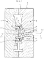
- Fig. 1 is a section view of main portions of the molding unit B of an injection molding apparatus to be used for embodying the present invention.
- This molding unit B comprises a pair of cavity molds 3, 4 forming a cavity C , a dummy boss shaft 5 disposed in the cavity C , and a nozzle 6 for injecting molten resin.
- a spool S is disposed in one cavity mold 3 out of the pair of cavity molds 3, 4.
- the nozzle 6 is connected to the spool S .
- a concave portion 31 having a spherical surface is formed in the cavity mold 3 at the innermost part thereof which communicates with the spool S .
- the dummy boss shaft 5 has a column-like shaft portion 51 to be fitted to the inner periphery of an inner ring 22 of the rolling bearing 2, and a flange 52 to be disposed along an end surface of the rolling bearing 2.
- the flange 52 has an outer diameter larger than the outer diameter of the shaft portion 51 and smaller than the outer diameter of the outer ring 21 of the rolling bearing 2.
- the flange 52 is provided at one lateral side thereof with a flat surface 52a at a right angle to the axis of the shaft portion 51.
- the flange 52 is provided at the other lateral side thereof with a spherical surface 52b.
- the outer peripheral edge of the flat surface 52a comes in close contact with the end surface of the outer ring 21 of the rolling bearing 2, such that the end surface of the rolling bearing 2 is hermetically sealed.
- the dummy boss shaft 5 is disposed such that the axis L1 thereof is located on a virtual extension line of the axis L2 of the spool S and the nozzle 6.
- the flange 52 is disposed in the concave portion 31 of the cavity mold 3 with a predetermined gap provided therebetween.
- the gap between the spherical surface 52b of the flange 52 and the concave portion 31, is formed as a runner R which communicates with the spool S .
- the gap between the outer peripheral edge of the spherical surface 52b and the opening edge of the concave portion 31, is formed as an annular film gate G .
- the film gate G is formed as coming in contact with the outer periphery of the end surface of the outer ring 21 of the rolling bearing 2.
- the film gate G has an outer diameter smaller than the outer diameter of the outer ring 21.
- the inner periphery of the inner ring 22 of the rolling bearing 2 is fitted to a core portion 41 of the cavity mold 4 with the molds opened. Then, the shaft portion 51 of the dummy boss shaft 5 is fitted to the inner periphery of the inner ring 22, and the flat surface 52a of the flange 52 is disposed along the end surface of the outer ring 21 of the rolling bearing 2. Then, the molds are closed and molten resin is injected through the nozzle 6. When introduced into the runner R through the spool S , the molten resin is concentrically spread and supplied into the cavity C through the annular film gate G .
- the dummy boss shaft 5 restrains the molten resin from entering the space defined by the inner periphery of the rolling bearing 2 and the gap between the inner ring 22 and the outer ring 21 thereof. Further, the dummy boss shaft 5 is adhered to the rolling bearing 2 by an injection pressure. This eliminates the need for disposing means for adhering the dummy boss shaft 5 to the rolling bearing 2.
- the molds are opened and the rolling bearing 2 is pushed, at the end surface thereof for example, by an ejector pin (not shown) such that the resin pulley A together with the dummy boss shaft 5 is released from the cavity mold 4. It is noted that the dummy boss shaft 5 may repeatedly be used as removed from the resin pulley A thus released from the mold 4.
- the film gate G is formed as coming in contact with the end surface of the outer ring 21 of the rolling bearing 2. Accordingly, the gate mark on the resin pulley A is put on the inner periphery of the resin body 1 at a position thereof which comes in contact with the end surface of the rolling bearing 2. Therefore, the position of the gate mark is shifted from the position where the rolling bearing 2 and the resin body 1 are relatively pressed due to a difference in thermal expansion between the rolling bearing 2 and the resin body 1. This makes it difficult that an internal stress generated in the resin body 1 due to a difference in thermal expansion, acts on the gate mark. This results in effective prevention of the occurrence of a crack at the gate mark portion even though the ambient temperature is low, i.e., even though the resin body 1 is great in low-temperature contraction.
- molten resin can be supplied into the cavity C from the side of the inner peripheral cylindrical portion 12 of the resin body 1 uniformly along the entire circumference thereof.
- the entire resin body 1 can uniformly be molded with high precision.
- the resin supplied into the cavity C can smoothly flow, the roundness of the outer peripheral cylindrical portion 11 of the resin body 1 can be enhanced.
- Fig. 3 is a graph showing the results of measurement of the roundness of the outer peripheral surface of a resin pulley molded by the film gate method above-mentioned.
- Fig. 4 is a graph showing the results of measurement of the roundness of the outer peripheral surface of a resin pulley molded by a conventional pin-point gate method.
- Each resin pulley subjected to the measurement was made of a nylon resin and had an outer diameter of 96mm. In the pinpoint gate method, the number of the gates was 19.
- the roundness of the resin pulley made by the film gate method was 40 ⁇ m, while the roundness of the resin pulley made by the pinpoint gate method was 100 ⁇ m.
- the film gate method considerably enhances the roundness as compared with the pinpoint gate method.
- the pinpoint gate method produced a ripple including irregularities in number equal to the gate number, but the film gate method produced no such a ripple.
- the film gate method can restrain the internal stress from remaining in the inner peripheral cylindrical portion 12 of the resin body 1. This not only prevents the roundness of the rolling bearing 2 from being deteriorated, but also prevents the radial gap from being reduced.
- the axis L1 of the dummy boss shaft 5 is located on a virtual extension line of the axis L2 of the spool S and the injection molding nozzle 6, and molten resin can be guided into the film gate G along the spherical surface 52b of the flange 52 of the dummy boss shaft 5.
- the molten resin can be guided to the film gate G very smoothly. Therefore, the molten resin can further uniformly be supplied into the cavity C .
- the resin body 1 can further be uniformly molded with high precision in its entirety.
- the gate portion of the resin pulley A can be cut when the resin pulley A is released from the mold.
- this not only eliminates the need for a gate treatment, but also minimizes a wasteful resin at the spool S and the runner R .
- Figs. 5, 6, 7 show the other examples of the film gate G .
- the film gate G in Fig. 1 is formed outside of the outer peripheral edge of the flange 52 of the dummy boss shaft 5 and between the end surface of the outer ring 21 of the rolling bearing 2 and the cavity mold 3.
- the film gate G in each of Figs. 5 and 6 is formed between the outer periphery of the lateral side of the flange 52 and the cavity mold 3.
- the film gates G in Figs. 5 and 6 are different in the following point.
- the film gate G in Fig. 5 is located in the inner peripheral cylindrical portion 12 of the resin body 1 at the intermediate portion of the inner peripheral surface of a flange 12a which covers a portion of the end surface of the outer ring 21.
- the film gate G in Fig. 6 is located at an end corner portion of the inner peripheral surface of the flange 12a.
- the film gate G in Fig. 7 is formed between the outer peripheral surface of the flange 52 of the dummy boss shaft 5 and the cavity mold 3 such that molten resin is axially injected into the cavity C .
- a step portion 52c is formed at the outer periphery of the flange 52 of the dummy boss shaft 5 and the film gate G is formed outside of the smallest-diameter portion of the flange 12a of the resin body 1.
- the injection pressure of molten resin acts on a lateral side of the step portion 52c of the dummy boss shaft 5 such that the flange 52 is liable to be separated from the outer ring 21.
- the method of molding a resin-covered article of the present invention is not limited to the embodiment above-mentioned, but a variety of modifications may be made.
- an ejector pin 7 may be disposed as passing through the center of the dummy boss shaft 5 and, together with the resin pulley A , the resin at each of the spool S and the runner R may be released from the mold (See Fig. 9).
- another metallic member such as a metallic hub 8 or the like may be inserted instead of the rolling bearing 2 (See Fig. 10).
- the shaft portion 51 of the dummy boss shaft 5 fitted to the inner periphery of the metallic member the dummy boss shaft 5 and the metallic member may be disposed in the cavity C .
- the resin to be used in the practice of the present invention a variety of synthetic resins may be used as far as they can be injection-molded. Instead of a synthetic resin, a synthetic rubber or the like may also be used.
Landscapes
- Engineering & Computer Science (AREA)
- General Engineering & Computer Science (AREA)
- Mechanical Engineering (AREA)
- Manufacturing & Machinery (AREA)
- Injection Moulding Of Plastics Or The Like (AREA)
- Moulds For Moulding Plastics Or The Like (AREA)
- Pulleys (AREA)
Applications Claiming Priority (3)
| Application Number | Priority Date | Filing Date | Title |
|---|---|---|---|
| JP309576/94 | 1994-11-18 | ||
| JP30957694A JP3301873B2 (ja) | 1994-11-18 | 1994-11-18 | 樹脂巻き部品の成形方法 |
| JP30957694 | 1994-11-18 |
Publications (2)
| Publication Number | Publication Date |
|---|---|
| EP0712708A1 true EP0712708A1 (de) | 1996-05-22 |
| EP0712708B1 EP0712708B1 (de) | 2001-04-25 |
Family
ID=17994699
Family Applications (1)
| Application Number | Title | Priority Date | Filing Date |
|---|---|---|---|
| EP95118161A Expired - Lifetime EP0712708B1 (de) | 1994-11-18 | 1995-11-17 | Verfahren zum Formen eines mit Kunststoff überzogenen Gegenstandes |
Country Status (4)
| Country | Link |
|---|---|
| US (1) | US5728343A (de) |
| EP (1) | EP0712708B1 (de) |
| JP (1) | JP3301873B2 (de) |
| DE (1) | DE69520776T2 (de) |
Cited By (9)
| Publication number | Priority date | Publication date | Assignee | Title |
|---|---|---|---|---|
| WO1999046099A1 (en) * | 1998-03-09 | 1999-09-16 | The Gates Corporation | Method of producing a plastic pulley with a metal insert |
| FR2776561A1 (fr) * | 1998-03-27 | 1999-10-01 | Skf Gmbh | Jante de galet ou de roulette realisee par moulage sur la bague exterieure d'un roulement |
| FR2844741A1 (fr) * | 2002-09-24 | 2004-03-26 | Freudenberg | Procede de fabrication d'une piece mecanique comportant une garniture en matiere plastique obtenue par surmoulage et piece obtenue par ce procede |
| EP1967347A1 (de) * | 2007-03-07 | 2008-09-10 | JTEKT Corporation | Harzkomponente |
| WO2013017187A1 (de) * | 2011-07-29 | 2013-02-07 | Robert Bosch Gmbh | Zahnradwellenanordnung |
| EP2853372A1 (de) * | 2013-09-30 | 2015-04-01 | Wilo Se | Spritzgusswerkzeug sowie Verfahren zur Herstellung eines hohlen Kunststoffformteils mittels Schirmanguss |
| WO2016116869A1 (en) * | 2015-01-20 | 2016-07-28 | Dem Automazioni S.R.L. | Pressing wheel |
| EP3266585A1 (de) * | 2016-07-06 | 2018-01-10 | Honginvest AG | Kunststoffverzahnungsteil |
| EP4112526A1 (de) * | 2021-06-28 | 2023-01-04 | Otis Elevator Company | Riemenscheibe für personenbeförderungsanlagen |
Families Citing this family (24)
| Publication number | Priority date | Publication date | Assignee | Title |
|---|---|---|---|---|
| JP3192082B2 (ja) * | 1996-02-14 | 2001-07-23 | 光洋精工株式会社 | 樹脂製プーリ |
| JP3299455B2 (ja) * | 1996-10-14 | 2002-07-08 | テイエチケー株式会社 | 転がり運動案内装置の移動ブロックの成形方法 |
| JP3948120B2 (ja) * | 1998-06-15 | 2007-07-25 | ソニー株式会社 | ガスケットとガスケットの成形方法及びこのガスケットを用いた円筒形アルカリ電池 |
| DE29922920U1 (de) * | 1999-02-12 | 2000-05-11 | Ensinger GmbH & Co., 71154 Nufringen | Rotationssymmetrisches Bauteil, wie Seilrollen, Laufrad o.dgl. aus Kunststoff |
| US6517251B1 (en) * | 1999-11-12 | 2003-02-11 | Black & Decker Inc. | Overmolded motor bearing and method of making same |
| US6367885B1 (en) * | 2000-06-09 | 2002-04-09 | Standex International Corporation | Molded wheel and bearing assembly |
| JP2004092688A (ja) | 2002-08-29 | 2004-03-25 | Koyo Seiko Co Ltd | 樹脂製プーリ |
| US6893599B2 (en) * | 2002-09-09 | 2005-05-17 | Patent Holding Company | Method for making a reinforced, polymeric article in a reaction injection molding system and mold for use therein |
| US7297081B2 (en) * | 2003-08-29 | 2007-11-20 | Dayco Products, Llc | Idler pulley with integral bearing carrier insert and method |
| EP1609997B1 (de) * | 2004-06-18 | 2007-08-08 | Electrolux Home Products Corporation N.V. | Lagerträger für ein Lüftergehäuse und Verfahren zu dessen Herstellung |
| JP4262711B2 (ja) | 2005-10-14 | 2009-05-13 | 大同メタル工業株式会社 | 樹脂被覆ベアリングの成形方法及び樹脂被膜ベアリングの製造方法並びにその成形方法で成形した樹脂被膜ベアリング |
| JP4228238B2 (ja) * | 2006-08-18 | 2009-02-25 | セイコーエプソン株式会社 | ローラ成形装置、ローラ成形用金型、ローラ製造方法 |
| JP4683001B2 (ja) * | 2007-03-27 | 2011-05-11 | トヨタ自動車株式会社 | 固定子のモールド成形装置、及び成形方法 |
| WO2008141466A1 (en) * | 2007-05-23 | 2008-11-27 | Litens Automotive Partnership | Center-gated molded pulley and method of manufacturing such a pulley |
| US20100184548A1 (en) * | 2007-06-15 | 2010-07-22 | Plastic Moldings Company, Llc | Injection molded pulleys having low levels of out-of-roundness |
| JP5224029B2 (ja) * | 2007-12-13 | 2013-07-03 | 株式会社ジェイテクト | 軸受付き樹脂プーリの製法 |
| JP5157675B2 (ja) * | 2008-06-24 | 2013-03-06 | スズキ株式会社 | 射出成形用金型及び樹脂成形品の成形方法 |
| US9180631B2 (en) * | 2011-07-22 | 2015-11-10 | The Boeing Company | Molded-in insert and method for fiber reinforced thermoplastic composite structure |
| JP2013161843A (ja) * | 2012-02-02 | 2013-08-19 | Tokai Rika Co Ltd | チップ部品の実装構造 |
| DE102012014660A1 (de) | 2012-07-24 | 2014-01-30 | Saurer Germany Gmbh & Co. Kg | Stützscheibenlagerung für eine Offenend-Spinneinrichtung |
| JP5852943B2 (ja) * | 2012-09-27 | 2016-02-03 | 日立アプライアンス株式会社 | 射出成形方法 |
| US20180236702A1 (en) * | 2015-01-26 | 2018-08-23 | Toskabano'k Co., Ltd. | Injection molding method using peek material and molded item |
| JP6610413B2 (ja) * | 2016-04-26 | 2019-11-27 | 中西金属工業株式会社 | インサート成形品の製造方法 |
| US11333235B2 (en) * | 2019-06-14 | 2022-05-17 | NHI Mechanical Motion, LLC | Hybrid drive component |
Citations (4)
| Publication number | Priority date | Publication date | Assignee | Title |
|---|---|---|---|---|
| FR1301211A (fr) * | 1961-09-20 | 1962-08-10 | Nestler Ag Albert | Palier à roulement radial enrobé par injection de matière synthétique, et moule ainsi que procédé pour cet enrobage par injection d'un palier à roulement |
| FR2554041A1 (fr) * | 1983-10-29 | 1985-05-03 | Skf Kugellagerfabriken Gmbh | Galet et dispositif pour sa fabrication |
| DE3420584A1 (de) * | 1984-05-07 | 1985-11-14 | Walter 7750 Konstanz Zepf | Lagerungs- und antriebselement |
| FR2572988A1 (fr) * | 1984-11-12 | 1986-05-16 | Nippon Seiko Kk | Poulie composee d'un roulement et d'un bandage en matiere plastique moulee |
Family Cites Families (3)
| Publication number | Priority date | Publication date | Assignee | Title |
|---|---|---|---|---|
| JPS5427501B2 (de) * | 1975-01-17 | 1979-09-10 | ||
| DE3339356A1 (de) * | 1983-10-29 | 1985-06-27 | SKF GmbH, 8720 Schweinfurt | Verfahren und vorrichtung zur herstellung von rollen |
| US4581806A (en) * | 1984-06-08 | 1986-04-15 | Futaba Bobbin Kabushiki Kaisha | Method of manufacturing bobbins for industrial use |
-
1994
- 1994-11-18 JP JP30957694A patent/JP3301873B2/ja not_active Expired - Lifetime
-
1995
- 1995-11-17 US US08/560,499 patent/US5728343A/en not_active Expired - Lifetime
- 1995-11-17 DE DE69520776T patent/DE69520776T2/de not_active Expired - Lifetime
- 1995-11-17 EP EP95118161A patent/EP0712708B1/de not_active Expired - Lifetime
Patent Citations (4)
| Publication number | Priority date | Publication date | Assignee | Title |
|---|---|---|---|---|
| FR1301211A (fr) * | 1961-09-20 | 1962-08-10 | Nestler Ag Albert | Palier à roulement radial enrobé par injection de matière synthétique, et moule ainsi que procédé pour cet enrobage par injection d'un palier à roulement |
| FR2554041A1 (fr) * | 1983-10-29 | 1985-05-03 | Skf Kugellagerfabriken Gmbh | Galet et dispositif pour sa fabrication |
| DE3420584A1 (de) * | 1984-05-07 | 1985-11-14 | Walter 7750 Konstanz Zepf | Lagerungs- und antriebselement |
| FR2572988A1 (fr) * | 1984-11-12 | 1986-05-16 | Nippon Seiko Kk | Poulie composee d'un roulement et d'un bandage en matiere plastique moulee |
Cited By (16)
| Publication number | Priority date | Publication date | Assignee | Title |
|---|---|---|---|---|
| WO1999046099A1 (en) * | 1998-03-09 | 1999-09-16 | The Gates Corporation | Method of producing a plastic pulley with a metal insert |
| CN1113736C (zh) * | 1998-03-09 | 2003-07-09 | 盖茨公司 | 生产具有一个金属插入件的塑料滑轮组件的方法 |
| FR2776561A1 (fr) * | 1998-03-27 | 1999-10-01 | Skf Gmbh | Jante de galet ou de roulette realisee par moulage sur la bague exterieure d'un roulement |
| US6142675A (en) * | 1998-03-27 | 2000-11-07 | Skf Gmbh | Roller having spindle fixed to inner bearing ring |
| FR2844741A1 (fr) * | 2002-09-24 | 2004-03-26 | Freudenberg | Procede de fabrication d'une piece mecanique comportant une garniture en matiere plastique obtenue par surmoulage et piece obtenue par ce procede |
| EP1403160A1 (de) * | 2002-09-24 | 2004-03-31 | Freudenberg | Herstellungsverfahren für Formteil mit angespritztem Dichtelement aus Kunststoff und Formteil herstellbar nach diesem Verfahren |
| EP1967347A1 (de) * | 2007-03-07 | 2008-09-10 | JTEKT Corporation | Harzkomponente |
| WO2013017187A1 (de) * | 2011-07-29 | 2013-02-07 | Robert Bosch Gmbh | Zahnradwellenanordnung |
| EP2853372A1 (de) * | 2013-09-30 | 2015-04-01 | Wilo Se | Spritzgusswerkzeug sowie Verfahren zur Herstellung eines hohlen Kunststoffformteils mittels Schirmanguss |
| CN104512009A (zh) * | 2013-09-30 | 2015-04-15 | 威乐欧洲股份公司 | 压铸模具以及借助伞形浇口制造空心塑料模制件的方法 |
| CN104512009B (zh) * | 2013-09-30 | 2018-01-05 | 威乐欧洲股份公司 | 压铸模具以及借助伞形浇口制造空心塑料模制件的方法 |
| WO2016116869A1 (en) * | 2015-01-20 | 2016-07-28 | Dem Automazioni S.R.L. | Pressing wheel |
| EP3266585A1 (de) * | 2016-07-06 | 2018-01-10 | Honginvest AG | Kunststoffverzahnungsteil |
| CH712699A1 (de) * | 2016-07-06 | 2018-01-15 | Honginvest Ag | Kunststoffverzahnungsteil. |
| EP4112526A1 (de) * | 2021-06-28 | 2023-01-04 | Otis Elevator Company | Riemenscheibe für personenbeförderungsanlagen |
| US12055206B2 (en) | 2021-06-28 | 2024-08-06 | Otis Elevator Company | Belt sheave for passenger conveyor systems |
Also Published As
| Publication number | Publication date |
|---|---|
| EP0712708B1 (de) | 2001-04-25 |
| JPH08142112A (ja) | 1996-06-04 |
| DE69520776D1 (de) | 2001-05-31 |
| US5728343A (en) | 1998-03-17 |
| JP3301873B2 (ja) | 2002-07-15 |
| DE69520776T2 (de) | 2002-05-08 |
Similar Documents
| Publication | Publication Date | Title |
|---|---|---|
| US5728343A (en) | Method of molding a resin pulley | |
| US4668209A (en) | Plastic-surrounded bearing | |
| US6941832B2 (en) | Injection molded resin gear, injection molded resin rotating body, and injection molded article | |
| EP0788872B1 (de) | Vorrichtung und Verfahren zur Herstellung einer Linse-Giessform mit einer sich im deren Zentrum befindenden Düse zur Herstellung von Kontakt-Linsen | |
| US20080219607A1 (en) | Resin wound component | |
| US4256140A (en) | Two-piece hot runner manifold | |
| US4455274A (en) | Method of producing a composite washer assembly | |
| US7537719B2 (en) | Method of manufacturing resin boot for constant-velocity universal joint | |
| JP6589585B2 (ja) | カバーの製造方法 | |
| EP0188338B1 (de) | Bandführung mit Blattfedern | |
| JPH06238711A (ja) | プラスチックの射出成形方法および装置 | |
| US5961905A (en) | Method of molding unitary roller of homogeneous material for tape cartridge | |
| US5456423A (en) | Tape reel with thin flange portions | |
| US20070200279A1 (en) | Circular Resin-Molded Product Having Circular Center Hole And Method And Apparatus For Molding The Same | |
| JPH01299363A (ja) | プーリおよびその製造方法 | |
| JP2005131834A (ja) | 射出成形用金型装置と射出成形方法 | |
| JPH09207163A (ja) | 軸受用シール及びその製造方法 | |
| JP7218627B2 (ja) | 回転角度検出装置用検出ギヤ、及び回転角度検出装置、並びに回転角度検出装置用検出ギヤの製造方法 | |
| JPS6351850B2 (de) | ||
| JP3259821B2 (ja) | 射出成形型 | |
| JP3621541B2 (ja) | ゴムローラ | |
| JP2002283353A (ja) | 金型装置 | |
| JPH02245515A (ja) | 軸受ブシュ、射出成形用型および軸受ブシュの製造方法 | |
| JPH0754966A (ja) | 樹脂成形品およびその射出成形方法 | |
| JP2006107555A (ja) | 光ディスク成形用金型装置 |
Legal Events
| Date | Code | Title | Description |
|---|---|---|---|
| PUAI | Public reference made under article 153(3) epc to a published international application that has entered the european phase |
Free format text: ORIGINAL CODE: 0009012 |
|
| AK | Designated contracting states |
Kind code of ref document: A1 Designated state(s): DE FR GB IT |
|
| RIN1 | Information on inventor provided before grant (corrected) |
Inventor name: UENO, HIROSHI |
|
| 17P | Request for examination filed |
Effective date: 19960424 |
|
| 17Q | First examination report despatched |
Effective date: 19981112 |
|
| GRAG | Despatch of communication of intention to grant |
Free format text: ORIGINAL CODE: EPIDOS AGRA |
|
| GRAG | Despatch of communication of intention to grant |
Free format text: ORIGINAL CODE: EPIDOS AGRA |
|
| GRAH | Despatch of communication of intention to grant a patent |
Free format text: ORIGINAL CODE: EPIDOS IGRA |
|
| GRAH | Despatch of communication of intention to grant a patent |
Free format text: ORIGINAL CODE: EPIDOS IGRA |
|
| GRAA | (expected) grant |
Free format text: ORIGINAL CODE: 0009210 |
|
| AK | Designated contracting states |
Kind code of ref document: B1 Designated state(s): DE FR GB IT |
|
| REF | Corresponds to: |
Ref document number: 69520776 Country of ref document: DE Date of ref document: 20010531 |
|
| ITF | It: translation for a ep patent filed | ||
| ET | Fr: translation filed | ||
| REG | Reference to a national code |
Ref country code: GB Ref legal event code: IF02 |
|
| PLBE | No opposition filed within time limit |
Free format text: ORIGINAL CODE: 0009261 |
|
| STAA | Information on the status of an ep patent application or granted ep patent |
Free format text: STATUS: NO OPPOSITION FILED WITHIN TIME LIMIT |
|
| 26N | No opposition filed | ||
| PGFP | Annual fee paid to national office [announced via postgrant information from national office to epo] |
Ref country code: GB Payment date: 20141112 Year of fee payment: 20 Ref country code: DE Payment date: 20141111 Year of fee payment: 20 Ref country code: FR Payment date: 20141110 Year of fee payment: 20 |
|
| PGFP | Annual fee paid to national office [announced via postgrant information from national office to epo] |
Ref country code: IT Payment date: 20141106 Year of fee payment: 20 |
|
| REG | Reference to a national code |
Ref country code: DE Ref legal event code: R071 Ref document number: 69520776 Country of ref document: DE |
|
| REG | Reference to a national code |
Ref country code: GB Ref legal event code: PE20 Expiry date: 20151116 |
|
| PG25 | Lapsed in a contracting state [announced via postgrant information from national office to epo] |
Ref country code: GB Free format text: LAPSE BECAUSE OF EXPIRATION OF PROTECTION Effective date: 20151116 |