EP0712736A2 - Méthode pour la fabrication de livres, brochures ou similaires reliés par adhésif - Google Patents
Méthode pour la fabrication de livres, brochures ou similaires reliés par adhésif Download PDFInfo
- Publication number
- EP0712736A2 EP0712736A2 EP95810706A EP95810706A EP0712736A2 EP 0712736 A2 EP0712736 A2 EP 0712736A2 EP 95810706 A EP95810706 A EP 95810706A EP 95810706 A EP95810706 A EP 95810706A EP 0712736 A2 EP0712736 A2 EP 0712736A2
- Authority
- EP
- European Patent Office
- Prior art keywords
- clamping
- holders
- blocks
- arrangement
- printed
- Prior art date
- Legal status (The legal status is an assumption and is not a legal conclusion. Google has not performed a legal analysis and makes no representation as to the accuracy of the status listed.)
- Granted
Links
- 238000000034 method Methods 0.000 title claims abstract description 14
- 239000003292 glue Substances 0.000 title abstract 2
- 238000012545 processing Methods 0.000 claims abstract description 25
- 239000011230 binding agent Substances 0.000 claims abstract description 17
- 239000000853 adhesive Substances 0.000 claims description 12
- 230000001070 adhesive effect Effects 0.000 claims description 12
- 238000004519 manufacturing process Methods 0.000 claims description 7
- 238000003825 pressing Methods 0.000 claims description 6
- 238000003754 machining Methods 0.000 claims description 3
- 230000002441 reversible effect Effects 0.000 claims description 2
- 238000011144 upstream manufacturing Methods 0.000 claims 1
- 238000012546 transfer Methods 0.000 description 8
- 230000006835 compression Effects 0.000 description 2
- 238000007906 compression Methods 0.000 description 2
- 239000000969 carrier Substances 0.000 description 1
- 238000004140 cleaning Methods 0.000 description 1
- 238000010276 construction Methods 0.000 description 1
- 238000011109 contamination Methods 0.000 description 1
- 238000013461 design Methods 0.000 description 1
- 238000011161 development Methods 0.000 description 1
- 238000006073 displacement reaction Methods 0.000 description 1
- 230000002349 favourable effect Effects 0.000 description 1
- 238000003032 molecular docking Methods 0.000 description 1
- 230000036314 physical performance Effects 0.000 description 1
- 230000002787 reinforcement Effects 0.000 description 1
- 238000007788 roughening Methods 0.000 description 1
- 238000009966 trimming Methods 0.000 description 1
Images
Classifications
-
- B—PERFORMING OPERATIONS; TRANSPORTING
- B42—BOOKBINDING; ALBUMS; FILES; SPECIAL PRINTED MATTER
- B42C—BOOKBINDING
- B42C19/00—Multi-step processes for making books
- B42C19/08—Conveying between operating stations in machines
-
- B—PERFORMING OPERATIONS; TRANSPORTING
- B65—CONVEYING; PACKING; STORING; HANDLING THIN OR FILAMENTARY MATERIAL
- B65H—HANDLING THIN OR FILAMENTARY MATERIAL, e.g. SHEETS, WEBS, CABLES
- B65H2301/00—Handling processes for sheets or webs
- B65H2301/40—Type of handling process
- B65H2301/43—Gathering; Associating; Assembling
- B65H2301/432—Gathering; Associating; Assembling in pockets, i.e. vertically
-
- B—PERFORMING OPERATIONS; TRANSPORTING
- B65—CONVEYING; PACKING; STORING; HANDLING THIN OR FILAMENTARY MATERIAL
- B65H—HANDLING THIN OR FILAMENTARY MATERIAL, e.g. SHEETS, WEBS, CABLES
- B65H2301/00—Handling processes for sheets or webs
- B65H2301/40—Type of handling process
- B65H2301/43—Gathering; Associating; Assembling
- B65H2301/435—Gathering; Associating; Assembling on collecting conveyor
- B65H2301/4354—Gathering; Associating; Assembling on collecting conveyor with grippers
-
- B—PERFORMING OPERATIONS; TRANSPORTING
- B65—CONVEYING; PACKING; STORING; HANDLING THIN OR FILAMENTARY MATERIAL
- B65H—HANDLING THIN OR FILAMENTARY MATERIAL, e.g. SHEETS, WEBS, CABLES
- B65H2301/00—Handling processes for sheets or webs
- B65H2301/40—Type of handling process
- B65H2301/44—Moving, forwarding, guiding material
- B65H2301/447—Moving, forwarding, guiding material transferring material between transport devices
- B65H2301/4471—Grippers, e.g. moved in paths enclosing an area
- B65H2301/44712—Grippers, e.g. moved in paths enclosing an area carried by chains or bands
Definitions
- the invention relates to a method for producing adhesive-bound books, brochures or the like.
- Products in which the printed sheets are continuously collated into loose printed sheet blocks according to a certain order for processing and / or adhesive connection of the folding or. Sheet edges of the printed sheets are transferred to book blocks on a circumferential clamping arrangement belonging to an adhesive binding device.
- the printed sheets - folded or single sheets - are collected or collated in a collator connected with an automatic perfect binder to loose book blocks or printed sheet blocks in a sequence determined by the feeder stations and a feeder control and via a transfer channel or. a transfer line fed to the perfect binder.
- the collating device After layering the printed sheets in the collecting channel the collating device is transported further with a change of direction by approximately 90 ° and subsequent erection of the complete printing sheet blocks by a turning movement in the transfer channel on the folded edges of the printing sheets which form the later book spine.
- the printed sheet blocks are fed to the clamping arrangement of the perfect binder, which is formed from collet chucks in which the processing and adhesive binding are carried out.
- the printing block in the transfer channel reach a speed of 2.54 m / s if an hourly production output of 15,000 copies is aimed for.
- an upper physical performance limit is reached, i.e. the desired goal of a higher throughput cannot be achieved by increasing the speed.
- the object of the invention is to provide a method of the type mentioned at the outset with which a higher production output than before can be achieved without loss of quality in the book blocks.
- this object is achieved in that the printed sheets, which are aligned after the fold in the conveying direction to form printed sheet blocks, are subsequently gripped by a clamping force and fed to the clamping arrangement driven in the same direction with an approximately vertical feed movement.
- the printing sheet blocks are formed by printing sheets which are strung together and extend transversely to the conveying direction built up.
- this procedure eliminates turning to set up the loose printing sheet blocks on a transfer line following the gathering, and thereby prevents the printing sheets from being displaced.
- the printed sheets are advantageously gathered standing on the fold, so that their loading is favored, and optionally fed to the clamping arrangement with the open side, the top or bottom side or the closed side in advance.
- a collating device which precedes a perfect binder formed from processing stations and collects printed sheets along lay-up stations according to a specific - also selective - sequence to loose printed sheet blocks, is provided, which has a rotating, the processing stations of the perfect binder assertive Clamping arrangement is effectively connected to the conveyor, which is characterized in that it (collating device) has a conveying device which forms a common conveying section with the clamping arrangement of the perfect binder, to which spaced, closable holders for receiving printing sheet blocks which form printing sheet blocks are fastened, and these holders between the conveying device and the the collets assigned to the binding device of the collet alternately decouplable form. This makes it easy to efficiently provide the printing block blocks before they are processed.
- the clamping arrangement Preferably, the clamping arrangement, respectively.
- the collets are preferably carried out above the processing stations of the perfect binder after the holder or the printing sheet blocks have been taken over, so that contamination of the clamping arrangement or the collets and holders can be largely prevented.
- the holders along the laying stations are assigned parallel moving frames from which the printed sheets are received.
- sockets are attached to a rotating traction element, which leaves the direction of movement of the sockets at the rear end of the docking stations.
- two walls are provided offset in the conveying direction, the spacing of which can be changed due to the different thickness of the printing sheet blocks or to hold the printing sheets together.
- At least one wall of the holder is supported against a reversible spring force when holding the printed sheets together, the latter being lifted by the book blocks at the latest when the holder is removed.
- a holder has proven to be a simple embodiment in which the lower end of the walls is formed by a cross member which can be displaced on a guide arrangement and which favors the stability and the adjustability of the walls.
- the collets are in turn formed by two carrier elements which extend transversely to the conveying direction and which are equipped with at least one positioning device for receiving the holders which are equipped with a sheet block, and which are adjustable in terms of distance, on each of which at least one presses with the other behind a notch for processing the book block spine cooperating, actuatable jaw is attached, ie that one of the jaws can be arranged stationary.
- Suitable as a simple positioning device for the printing sheet blocks are two grooves which correspond to the cross members and are arranged distributed on and on the carrier elements.
- a reference position provided for determining the transverse position of a printing sheet block can be provided by a pin and a bore in the carrier elements corresponding to this.
- a controlled tappet arrangement for actuating at least one clamping jaw against the other, with a printing sheet block lying or hanging between them, which triggers a pivoting movement of the clamping jaw for pressing the printing sheet block.
- At least one of them can be locked in a force-locking or positive-locking manner, as long as the machining process has not ended.
- At least one support element is adjustably arranged and can be actuated accordingly by an acting control device. This is particularly necessary before the holder is attached to the sheet block and when the holder is removed from the collet.
- the collets are preferably guided by rollers, sliding blocks or the like.
- Guide elements which are provided at the articulation point of the traction means on the connecting elements or on the latter and which engage in a guide groove of a frame or machine stand.
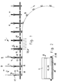
- a conveyor device 1 of a collating device 2 is shown along two feed stations 3, 4.
- a transfer of the printed sheet blocks 11 formed after the collation to the collets 10 can take place both from below and from above through the collets, the open sides of the printed sheets 7 of a printed sheet block 11 being guided through the collets 10 in advance.
- the holder 6 on the conveyor 1 of the collating device 2 consist of two approximately parallel spaced walls 12, 13, which are designed to be divergent at the loading opening 14 and on the opposite side create a container-like shape on the opposite side by frames 15 that move in the same direction.
- the sockets 15, which are assigned to the holders 6, are also attached to a rotating drive element 16, which at the end of the collation device 2, after the action of a force or. Spring force on at least one wall 12, 13 away from the path of movement of the holder 6, so that the sockets 15 are lifted off the finished printed sheet blocks 11.
- the sockets 15 shown have a base on / on which the printed sheets 7 are aligned, but instead of a base on the length of the collating section, a guide surface could be provided which extends at least until the closing force of the holders 6 is applied.
- Fig. 1 acting on the walls 12, 13 pressure springs 17 are shown, which are guided on guide rods 18.
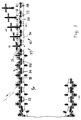
- FIG. 2 in conjunction with FIG. 1 illustrates the configuration of the container-like shape of the holder 6 in cooperation with the sockets 15, the lower edge of the walls 12, 13 for their reinforcement and for receiving the compression spring device 17, 18 with a cross member 19 is trained.
- a vibrating device designated 20, is arranged, which, before the walls 12, 13 are actuated to form a compressed printing sheet block 11, ensures that the printing sheets 7 lie evenly in the holders 15.
- This is done by changing the holders 6, which are decoupled from the pulling means 5 into the collets 10, the feed of the holders 6 starting on the side of the collets 10 facing the processing stations of the perfect binder.
- the holder 6 thus alternately forms part of the collating device 2 or.
- Collets 10 dip with the open sides of the printed sheets 7 into the collets 10 controlled in the open position and are locked or anchored in their processing position by a controlled closing movement.
- the collets 10 each have two carrier elements 21, 22 extending transversely to the conveying direction, the mutual spacing of which can be adjusted in the conveying direction, such that their inner sides abut against the cheeks 12, 13 of the holder 6 without pressing the printed sheet blocks 11.
- Sheet blocks 11 in the collets 10 are each made by a groove 32 which extends transversely in a carrier element 21, 22 and into which the transverse carriers 19 of the holders 6 are immersed during a closing movement of the carrier elements 21, 22. This position is also the reference position for the later processing of the printing block 11 in the perfect binder.
- the side position of the holder 6 and. the printing sheet blocks is brought about by a positioning device 23 recognizable in FIG. 5.
- the carrier elements 21, 22 each have a clamping jaw 24, 25, at least one of which, with the other, has a release of the printing sheet block intended for processing 11 forms a cooperating press or is drivable.
- the present exemplary embodiment has two clamping jaws 24, 25 which can be driven against one another and are pressed laterally by controllable tappet arrangements 26 against the printed sheet block 11 suspended therebetween. This construction allows the clamping jaws 24, 25 to be detached from the printed sheet block 11 in order to change the notch during the processing of a printed sheet block 11 in the perfect binder.
- the tappet arrangements 26 which act on the pivotably arranged clamping jaws 24, 25 each consist of a central shaft 27, on which ram 28, which is distributed over the width of a support element 21, 22, is mounted or fastened to the support elements 21, 22 and which is secured by a to the Roller ends attached roller 29 can be driven by a control device (not shown).
- a control device not shown
- the latter are connected by a circular rod 30 acting on the clamping jaw 24, 25, which holds the clamping jaw 24, 25 by constant pressure in the pressing position until the machining of the Book block spine no longer requires this.
- the plungers 28 are then brought back to an unrecognizable control track by running up the rollers 29 and are held in their rest position by the springs 31 installed in the carrier elements 21, 22.
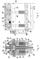
- FIG. 3 shows the arrangement of the carrier elements 21, 22 or collets 10 within the clamping arrangement 8 of an adhesive binder.
- the carrier element 22 trailing in the conveying direction is displaceably guided or arranged in an adjusting element 34 of traction element sections 35 - here link chains 36 - of a traction element 37 with regard to the adjustability of the collet opening 33.
- the opening size is changed by the action of a control which opens the collet 10 before the holder 6 is fed in and closes again before its decoupling from the traction means 5.
- both carrier elements 21, 22 could be arranged on the connecting element 34 so as to be adjustable with respect to changing the collet opening.
- the leading carrier element 21 is firmly connected to the connecting element 34.
- a partially illustrated strand of the clamping arrangement 8 forming the common conveying section 9 is guided in a lateral guide arrangement 38, the traction means sections 35 having a guide roller 39 or a sliding block at the ends coupled to the connecting elements 34.
- the guide roller 39 can be seen in FIG. 3 on the side of the connecting elements 34 facing the viewer.
- the mode of operation of the device according to the invention is described below with reference to the figures.
- Fig. 1 the loading of the holder 6 of the conveyor 1 on the collating device 2 is shown.
- the printing sheets 7 fed from feed stations 3, 4 form a printing sheet block 11 which builds up in the conveying direction.
- the printing sheets in the sockets 15, which move in the same direction, are displaced by a vibrating device 20 against a contact surface and then held together by the compression spring device 17, 18 so that they cannot be displaced.
- the printed sheet blocks 11 in the holders 6 reach a common conveying section 9 on the clamping arrangement 8 (see FIG. 3).
- the conveying section 9 - transfer section - both the conveying device 1 and the clamping arrangement 8 or the collets 10 have the same speed.
- the holders 6 are decoupled from the traction means 5 transfers the clamping arrangement 8, which is controlled on the conveying section 9 into a closed position, so that the holder 6 or the printed sheet blocks 11 hang firmly in the collets 10.
- the printed sheet blocks 11 are pressed together by actuating the clamping jaws 24, 25 on or in front of the notch, in that a torsion spring 40 arranged on the shaft 27 triggers a pivoting movement of the clamping jaws 24, 25 by the action of a control element, so that they on the notch of the book blocks come into contact and then put into a pressing position by lifting the plunger 28 and in this way guided through the processing stations of the perfect binder.
- the removal of the glued book blocks at the end of the perfect binding process is carried out by lifting the holder 6 out of the open collets 10, for example on a second common conveyor section, where the clamping arrangement 8 or. hit the collets 10 and the traction mechanism 5 of the conveyor 1 again. The book block is then removed from the holder 6.
Landscapes
- Collation Of Sheets And Webs (AREA)
Applications Claiming Priority (4)
| Application Number | Priority Date | Filing Date | Title |
|---|---|---|---|
| CH3479/94 | 1994-11-18 | ||
| CH347994 | 1994-11-18 | ||
| CH378194 | 1994-12-14 | ||
| CH3781/94 | 1994-12-14 |
Publications (3)
| Publication Number | Publication Date |
|---|---|
| EP0712736A2 true EP0712736A2 (fr) | 1996-05-22 |
| EP0712736A3 EP0712736A3 (fr) | 1996-10-30 |
| EP0712736B1 EP0712736B1 (fr) | 1999-02-10 |
Family
ID=25693114
Family Applications (1)
| Application Number | Title | Priority Date | Filing Date |
|---|---|---|---|
| EP95810706A Expired - Lifetime EP0712736B1 (fr) | 1994-11-18 | 1995-11-09 | Méthode pour la fabrication de livres, brochures ou similaires reliés par adhésif |
Country Status (3)
| Country | Link |
|---|---|
| US (1) | US5788446A (fr) |
| EP (1) | EP0712736B1 (fr) |
| DE (1) | DE59505081D1 (fr) |
Cited By (4)
| Publication number | Priority date | Publication date | Assignee | Title |
|---|---|---|---|---|
| EP0732222B1 (fr) * | 1995-03-16 | 1999-09-15 | Grapha-Holding Ag | Méthode et dispositif pour attacher une couverture sur le dos d'un livre, constitué de feuilles imprimées et reliées |
| EP1254857A3 (fr) * | 2001-04-26 | 2003-01-29 | Ferag AG | Dispositif pour assembler des articles plats en piles et pour le traitement ultérieur de la pile |
| EP1655148A1 (fr) | 2004-11-08 | 2006-05-10 | Müller Martini Holding AG | Dispositif pour la reliure par adhésif de produits imprimés pour la production d'un ouvrage imprimé |
| EP2514603A1 (fr) * | 2011-04-23 | 2012-10-24 | Kolbus GmbH & Co. KG | Dispositif de transport de blocs de livres vers une machine de reliure de livres |
Families Citing this family (9)
| Publication number | Priority date | Publication date | Assignee | Title |
|---|---|---|---|---|
| DE19859333A1 (de) * | 1998-12-22 | 2000-07-06 | Kolbus Gmbh & Co Kg | Buchfertigungsstraße |
| ITMI20010137A1 (it) * | 2000-02-12 | 2002-07-25 | Kolbus Gmbh & Co Kg | Procedimento per la rilegatura di un blocco di libro o di opuscolo inuna copertina e dispositivo per l'esecuzione del procedimento |
| US6447229B1 (en) * | 2000-05-12 | 2002-09-10 | Heidelberger Druckmaschinen Ag | Device and method for preparing a book spine for binding |
| US6514028B2 (en) | 2000-05-17 | 2003-02-04 | Heidelberger Druckmaschinen Ag | Device and method for side wire binding |
| US6547501B2 (en) * | 2001-03-22 | 2003-04-15 | Heidelberger Druckmaschinen Ag | Device and method for binding printed products |
| DE102005005652A1 (de) * | 2005-02-08 | 2006-09-14 | Kolbus Gmbh & Co. Kg | Buchblockzange |
| US7547008B2 (en) * | 2005-12-15 | 2009-06-16 | Goss International Americas, Inc. | Printed product collecting device and method |
| US7588236B2 (en) * | 2006-02-23 | 2009-09-15 | Goss International Americas, Inc. | Device for gathering printed products |
| EP3406456B1 (fr) * | 2017-05-24 | 2019-08-21 | Müller Martini Holding AG | Encolleuse |
Family Cites Families (17)
| Publication number | Priority date | Publication date | Assignee | Title |
|---|---|---|---|---|
| FR666609A (fr) * | 1928-03-01 | 1929-10-03 | Fortuna Werke Spezialmaschinen | Appareil à dégager les brochures des machines à couvrir |
| US2755491A (en) * | 1953-06-15 | 1956-07-24 | Andrew J Terzuoli | Method of and apparatus for bookbinding |
| DE1077181B (de) * | 1957-11-23 | 1960-03-10 | Prakma Maschinenfabrik G M B H | Einpressvorrichtung an Maschinen zum Herstellen von Broschueren |
| FR1236038A (fr) * | 1959-06-02 | 1960-07-15 | Machine effectuant de façon entièrement automatique la mise sous presse, le taquage, l'encollage et le séchage des volumes | |
| DE1214194B (de) * | 1960-07-07 | 1966-04-14 | Grossbuchbinderei Paul Altmann | Verfahren und Vorrichtung zum Herstellen von Buechern und Broschueren |
| CH412798A (de) * | 1964-02-21 | 1966-05-15 | Mueller Hans Grapha Masch | Verfahren und Maschine zum Klebebinden von Broschüren und Büchern mit beidseitigen Vorsatzbogen |
| DE1786262B1 (de) * | 1968-09-07 | 1971-11-18 | Walter Sigloch Grossbuchbinder | Verfahren und vorrichtung zum anlegen eines buchblocks an eine beschneidemaschine |
| GB1463302A (en) * | 1973-08-09 | 1977-02-02 | Glass Tubes & Components Ltd | Self-centering chuck |
| DE3107458A1 (de) * | 1981-02-27 | 1982-09-16 | Rahdener Maschinenfabrik August Kolbus Gmbh & Co Kg, 4993 Rahden | Buchblockzange fuer transportsystem |
| DE3207102C2 (de) * | 1982-02-27 | 1987-01-15 | Kolbus GmbH & Co KG, 4993 Rahden | Buchblockzange |
| DE3361987D1 (en) * | 1982-06-02 | 1986-03-13 | Ferag Ag | Device for transporting continuously supplied flat paper products |
| DE3413222C2 (de) * | 1984-04-07 | 1995-02-09 | Kolbus Gmbh & Co Kg | Verfahren zum Überführen von Buchblocks in das Transportmittel einer Buchbindemaschine und Vorrichtung zur Durchführung des Verfahrens |
| ATE46489T1 (de) * | 1986-04-18 | 1989-10-15 | Ferag Ag | Verfahren und vorrichtung zum wenden kontinuierlich gefoerderter flaechengebilde. |
| DE3670195D1 (de) * | 1986-09-15 | 1990-05-17 | Pfaff Ind Masch | Verfahren und vorrichtung zur relativpositionierung von biegeschlaffen werkstuecklagen. |
| SU1425029A1 (ru) * | 1986-12-22 | 1988-09-23 | Филиал Ростовского Научно-Исследовательского Института Технологии Машиностроения В Г.Ровно | Многоместное устройство дл зажима деталей |
| SU1532319A1 (ru) * | 1987-04-03 | 1989-12-30 | Bauman Artur G | Способ изготовлени книги с бесшвейным скреплением тетрадей в блок без срезки фальцев и устройство дл его осуществлени |
| DE4218421A1 (de) * | 1992-06-04 | 1993-12-09 | Heidelberger Druckmasch Ag | Bogenführung im Ausleger einer Druckmaschine |
-
1995
- 1995-11-09 EP EP95810706A patent/EP0712736B1/fr not_active Expired - Lifetime
- 1995-11-09 DE DE59505081T patent/DE59505081D1/de not_active Expired - Fee Related
- 1995-11-13 US US08/556,008 patent/US5788446A/en not_active Expired - Fee Related
Non-Patent Citations (1)
| Title |
|---|
| None |
Cited By (6)
| Publication number | Priority date | Publication date | Assignee | Title |
|---|---|---|---|---|
| EP0732222B1 (fr) * | 1995-03-16 | 1999-09-15 | Grapha-Holding Ag | Méthode et dispositif pour attacher une couverture sur le dos d'un livre, constitué de feuilles imprimées et reliées |
| EP1254857A3 (fr) * | 2001-04-26 | 2003-01-29 | Ferag AG | Dispositif pour assembler des articles plats en piles et pour le traitement ultérieur de la pile |
| US6708968B2 (en) | 2001-04-26 | 2004-03-23 | Ferag Ag | Device for gathering flat articles into stacks and for further processing the stacks |
| EP1655148A1 (fr) | 2004-11-08 | 2006-05-10 | Müller Martini Holding AG | Dispositif pour la reliure par adhésif de produits imprimés pour la production d'un ouvrage imprimé |
| US7748940B2 (en) | 2004-11-08 | 2010-07-06 | Müller Martini Holdings AG | Apparatus for the perfect binding of print products to form print articles |
| EP2514603A1 (fr) * | 2011-04-23 | 2012-10-24 | Kolbus GmbH & Co. KG | Dispositif de transport de blocs de livres vers une machine de reliure de livres |
Also Published As
| Publication number | Publication date |
|---|---|
| EP0712736B1 (fr) | 1999-02-10 |
| DE59505081D1 (de) | 1999-03-25 |
| EP0712736A3 (fr) | 1996-10-30 |
| US5788446A (en) | 1998-08-04 |
Similar Documents
| Publication | Publication Date | Title |
|---|---|---|
| EP2457738B1 (fr) | Procédé de reliure par collage d'un bloc de livre avec feuille de garde | |
| EP0476718B1 (fr) | Dispositif pour piquer des produits d'imprimerie à plusieurs parties | |
| DE3141686C2 (de) | Verfahren und Vorrichtung zum Herstellen von Blöcken mit Drahtkammbindung | |
| EP0712736B1 (fr) | Méthode pour la fabrication de livres, brochures ou similaires reliés par adhésif | |
| EP0623542A1 (fr) | Dispositif pour empiler un chant de feuilles imprimées | |
| DE3413222C2 (de) | Verfahren zum Überführen von Buchblocks in das Transportmittel einer Buchbindemaschine und Vorrichtung zur Durchführung des Verfahrens | |
| DE2630161C3 (de) | Verfahren und Vorrichtung zur Herstellung von gehefteten Büchern | |
| EP2517892B1 (fr) | Dispositif et procédé de fabrication d'un bloc de livre relié présentant une bande à onglets ou une couverture | |
| EP1674285B1 (fr) | Machine pour former et pincer des livres | |
| DE2508745A1 (de) | Vorrichtung zum aufstauen vereinzelt vorgeschobener papierboegen zu stapeln und zum weitertransportieren dieser stapel | |
| EP1942009B1 (fr) | Machine pour former et pincer des livres avec amenée de livres | |
| EP0418529A2 (fr) | Appareil pour limiter des feuilles imprimées à trois côtés | |
| EP1405809A1 (fr) | Dispositif pour former des colis de produits empilés | |
| EP0732222B1 (fr) | Méthode et dispositif pour attacher une couverture sur le dos d'un livre, constitué de feuilles imprimées et reliées | |
| EP1886833A1 (fr) | Procédé et dispositif de fabrication d'un objet imprimé relié par adhésif à partir de plusieurs produits imprimés | |
| EP2468665B1 (fr) | Dispositif destiné à l'installation d'une couverture de livre | |
| EP1213245B1 (fr) | Procédé et dispositif de pliage de feuilles | |
| EP0806392A2 (fr) | Méthode d'assemblage de produits imprimés en produits imprimés assemblés | |
| EP0976672A2 (fr) | Dispositif de transport | |
| DE1561141A1 (de) | Vorrichtung zum OEffnen eines mehrblaettrigen Papiererzeugnisses an einer durch Reibungsminderung vorbestimmten Stelle und zum Einfuehren einer Beilage in das geoeffnete Erzeugnis | |
| EP2030801B1 (fr) | Procédé pour la reliure par adhésif de produits imprimés pour la production d'un ouvrage imprimé et dispositif correspondant | |
| EP1655148B1 (fr) | Dispositif pour la reliure par adhésif de produits imprimés pour la production d'un ouvrage imprimé | |
| DE2220567A1 (de) | Verfahren und vorrichtung zum buchbinden | |
| EP2287010B1 (fr) | Procédé pour la liaison d'une couverture de livre sur des surfaces extérieures encollées d'un bloc de livres | |
| EP2508351A2 (fr) | Dispositif destiné à la fabrication d'un bloc de livre |
Legal Events
| Date | Code | Title | Description |
|---|---|---|---|
| PUAI | Public reference made under article 153(3) epc to a published international application that has entered the european phase |
Free format text: ORIGINAL CODE: 0009012 |
|
| AK | Designated contracting states |
Kind code of ref document: A2 Designated state(s): CH DE FR GB IT LI |
|
| PUAL | Search report despatched |
Free format text: ORIGINAL CODE: 0009013 |
|
| AK | Designated contracting states |
Kind code of ref document: A3 Designated state(s): CH DE FR GB IT LI |
|
| 17P | Request for examination filed |
Effective date: 19970205 |
|
| GRAG | Despatch of communication of intention to grant |
Free format text: ORIGINAL CODE: EPIDOS AGRA |
|
| GRAG | Despatch of communication of intention to grant |
Free format text: ORIGINAL CODE: EPIDOS AGRA |
|
| GRAH | Despatch of communication of intention to grant a patent |
Free format text: ORIGINAL CODE: EPIDOS IGRA |
|
| 17Q | First examination report despatched |
Effective date: 19980327 |
|
| GRAH | Despatch of communication of intention to grant a patent |
Free format text: ORIGINAL CODE: EPIDOS IGRA |
|
| GRAA | (expected) grant |
Free format text: ORIGINAL CODE: 0009210 |
|
| AK | Designated contracting states |
Kind code of ref document: B1 Designated state(s): CH DE FR GB IT LI |
|
| REG | Reference to a national code |
Ref country code: CH Ref legal event code: EP |
|
| GBT | Gb: translation of ep patent filed (gb section 77(6)(a)/1977) |
Effective date: 19990223 |
|
| REF | Corresponds to: |
Ref document number: 59505081 Country of ref document: DE Date of ref document: 19990325 |
|
| ITF | It: translation for a ep patent filed | ||
| ET | Fr: translation filed | ||
| PLBE | No opposition filed within time limit |
Free format text: ORIGINAL CODE: 0009261 |
|
| STAA | Information on the status of an ep patent application or granted ep patent |
Free format text: STATUS: NO OPPOSITION FILED WITHIN TIME LIMIT |
|
| 26N | No opposition filed | ||
| REG | Reference to a national code |
Ref country code: GB Ref legal event code: IF02 |
|
| PGFP | Annual fee paid to national office [announced via postgrant information from national office to epo] |
Ref country code: FR Payment date: 20021022 Year of fee payment: 8 |
|
| PGFP | Annual fee paid to national office [announced via postgrant information from national office to epo] |
Ref country code: GB Payment date: 20021030 Year of fee payment: 8 |
|
| PGFP | Annual fee paid to national office [announced via postgrant information from national office to epo] |
Ref country code: DE Payment date: 20021108 Year of fee payment: 8 |
|
| PGFP | Annual fee paid to national office [announced via postgrant information from national office to epo] |
Ref country code: CH Payment date: 20030220 Year of fee payment: 8 |
|
| PG25 | Lapsed in a contracting state [announced via postgrant information from national office to epo] |
Ref country code: GB Free format text: LAPSE BECAUSE OF NON-PAYMENT OF DUE FEES Effective date: 20031109 |
|
| PG25 | Lapsed in a contracting state [announced via postgrant information from national office to epo] |
Ref country code: LI Free format text: LAPSE BECAUSE OF NON-PAYMENT OF DUE FEES Effective date: 20031130 Ref country code: CH Free format text: LAPSE BECAUSE OF NON-PAYMENT OF DUE FEES Effective date: 20031130 |
|
| PG25 | Lapsed in a contracting state [announced via postgrant information from national office to epo] |
Ref country code: DE Free format text: LAPSE BECAUSE OF NON-PAYMENT OF DUE FEES Effective date: 20040602 |
|
| GBPC | Gb: european patent ceased through non-payment of renewal fee |
Effective date: 20031109 |
|
| REG | Reference to a national code |
Ref country code: CH Ref legal event code: PL |
|
| PG25 | Lapsed in a contracting state [announced via postgrant information from national office to epo] |
Ref country code: FR Free format text: LAPSE BECAUSE OF NON-PAYMENT OF DUE FEES Effective date: 20040730 |
|
| REG | Reference to a national code |
Ref country code: FR Ref legal event code: ST |
|
| PG25 | Lapsed in a contracting state [announced via postgrant information from national office to epo] |
Ref country code: IT Free format text: LAPSE BECAUSE OF NON-PAYMENT OF DUE FEES;WARNING: LAPSES OF ITALIAN PATENTS WITH EFFECTIVE DATE BEFORE 2007 MAY HAVE OCCURRED AT ANY TIME BEFORE 2007. THE CORRECT EFFECTIVE DATE MAY BE DIFFERENT FROM THE ONE RECORDED. Effective date: 20051109 |