EP2514603A1 - Dispositif de transport de blocs de livres vers une machine de reliure de livres - Google Patents
Dispositif de transport de blocs de livres vers une machine de reliure de livres Download PDFInfo
- Publication number
- EP2514603A1 EP2514603A1 EP12002764A EP12002764A EP2514603A1 EP 2514603 A1 EP2514603 A1 EP 2514603A1 EP 12002764 A EP12002764 A EP 12002764A EP 12002764 A EP12002764 A EP 12002764A EP 2514603 A1 EP2514603 A1 EP 2514603A1
- Authority
- EP
- European Patent Office
- Prior art keywords
- conveyor
- clamping
- block
- sheet
- book
- Prior art date
- Legal status (The legal status is an assumption and is not a legal conclusion. Google has not performed a legal analysis and makes no representation as to the accuracy of the status listed.)
- Withdrawn
Links
- 230000027455 binding Effects 0.000 title description 5
- 238000009739 binding Methods 0.000 title description 5
- 238000012546 transfer Methods 0.000 claims abstract description 16
- 230000001360 synchronised effect Effects 0.000 claims abstract description 5
- 230000001914 calming effect Effects 0.000 claims description 6
- 210000002105 tongue Anatomy 0.000 claims description 2
- 239000011230 binding agent Substances 0.000 description 14
- 239000000853 adhesive Substances 0.000 description 7
- 230000001070 adhesive effect Effects 0.000 description 7
- 238000011161 development Methods 0.000 description 4
- 238000006073 displacement reaction Methods 0.000 description 3
- 238000012545 processing Methods 0.000 description 3
- 230000001419 dependent effect Effects 0.000 description 2
- 238000001035 drying Methods 0.000 description 2
- 230000007717 exclusion Effects 0.000 description 2
- 238000009434 installation Methods 0.000 description 2
- 238000000034 method Methods 0.000 description 2
- 238000011144 upstream manufacturing Methods 0.000 description 2
- 206010015137 Eructation Diseases 0.000 description 1
- 206010067171 Regurgitation Diseases 0.000 description 1
- 238000004026 adhesive bonding Methods 0.000 description 1
- 208000027687 belching Diseases 0.000 description 1
- 230000003750 conditioning effect Effects 0.000 description 1
- 238000010276 construction Methods 0.000 description 1
- 230000008878 coupling Effects 0.000 description 1
- 238000010168 coupling process Methods 0.000 description 1
- 238000005859 coupling reaction Methods 0.000 description 1
- 238000009499 grossing Methods 0.000 description 1
- 238000004519 manufacturing process Methods 0.000 description 1
- 238000013508 migration Methods 0.000 description 1
- 230000005012 migration Effects 0.000 description 1
- 230000002028 premature Effects 0.000 description 1
- 230000000284 resting effect Effects 0.000 description 1
- 238000000926 separation method Methods 0.000 description 1
- 239000007787 solid Substances 0.000 description 1
Images


Classifications
-
- B—PERFORMING OPERATIONS; TRANSPORTING
- B42—BOOKBINDING; ALBUMS; FILES; SPECIAL PRINTED MATTER
- B42C—BOOKBINDING
- B42C19/00—Multi-step processes for making books
- B42C19/08—Conveying between operating stations in machines
-
- B—PERFORMING OPERATIONS; TRANSPORTING
- B65—CONVEYING; PACKING; STORING; HANDLING THIN OR FILAMENTARY MATERIAL
- B65H—HANDLING THIN OR FILAMENTARY MATERIAL, e.g. SHEETS, WEBS, CABLES
- B65H3/00—Separating articles from piles
- B65H3/46—Supplementary devices or measures to assist separation or prevent double feed
- B65H3/60—Loosening articles in piles
- B65H3/62—Loosening articles in piles by swinging, agitating, or knocking the pile
-
- B—PERFORMING OPERATIONS; TRANSPORTING
- B42—BOOKBINDING; ALBUMS; FILES; SPECIAL PRINTED MATTER
- B42C—BOOKBINDING
- B42C11/00—Casing-in
- B42C11/02—Machines or equipment for casing-in or applying covers to pamphlets, magazines, pads, or other paper-covered booklets
-
- B—PERFORMING OPERATIONS; TRANSPORTING
- B65—CONVEYING; PACKING; STORING; HANDLING THIN OR FILAMENTARY MATERIAL
- B65H—HANDLING THIN OR FILAMENTARY MATERIAL, e.g. SHEETS, WEBS, CABLES
- B65H2301/00—Handling processes for sheets or webs
- B65H2301/40—Type of handling process
- B65H2301/42—Piling, depiling, handling piles
- B65H2301/422—Handling piles, sets or stacks of articles
- B65H2301/4222—Squaring-up piles
-
- B—PERFORMING OPERATIONS; TRANSPORTING
- B65—CONVEYING; PACKING; STORING; HANDLING THIN OR FILAMENTARY MATERIAL
- B65H—HANDLING THIN OR FILAMENTARY MATERIAL, e.g. SHEETS, WEBS, CABLES
- B65H2301/00—Handling processes for sheets or webs
- B65H2301/40—Type of handling process
- B65H2301/42—Piling, depiling, handling piles
- B65H2301/422—Handling piles, sets or stacks of articles
- B65H2301/4226—Delivering, advancing piles
- B65H2301/42265—Delivering, advancing piles by moving the surface supporting the pile of articles on edge, e.g. conveyor or carriage
-
- B—PERFORMING OPERATIONS; TRANSPORTING
- B65—CONVEYING; PACKING; STORING; HANDLING THIN OR FILAMENTARY MATERIAL
- B65H—HANDLING THIN OR FILAMENTARY MATERIAL, e.g. SHEETS, WEBS, CABLES
- B65H2801/00—Application field
- B65H2801/48—Bookbinding
Definitions
- the invention relates to a device for feeding book blocks to a bookbinding machine according to the preamble of claim 1.
- the DE 20 2005 007 012 U1 shows such a bookbinding machine with a book block conveyor, consisting of an endless continuously around deflection wheels running conveyor and a plurality of mutually spaced at a same mutual distance from each other on the conveyor brackets for clamping book block. Along linear conveying paths of the oval different processing stations are arranged. There are also linearly running perfect binder known with a clamping plate conveyor of two rotating plate chains, between which the book blocks are clamped and transported at fixed intervals.
- the loose book blocks pass through a transfer channel into the perfect binder, the book blocks being progressively advanced by bar conveyors in a channel having a bottom and lateral guide walls, passing one or more vibrating stations.
- the book blocks which are transported on their backs in the longitudinal direction of the back, are guided over vibrating plates embedded in the floor and aligned in the back and on the head so that all folded sheets and / or single sheets lie in one plane.
- the invention has for its object to provide a device for feeding book block to a bookbinding machine according to the preamble of claim 1, which, with a simple construction, a proper alignment and transfer of particular sheet pilings formed from individual sheets, respectively. Bookblocks even at higher production speeds.
- the vibrator has at least one inclined to the horizontal first vibrating plate on which the stack of sheets standing on first sheet edges, under conditioning second sheet edges on a rectilinear plane to the first Haittelplatte stationary alignment element aligned and that the conveyor as Clamping conveyor is designed to take over aligned sheet stack from the inclined, stationary position in the vibrator and the synchronous, positive transfer to the continuously driven book block conveyor with horizontally lying block back.
- the stacks of sheets are no longer pushed through a channel in the perfect binder, but transported clamped by the clamping conveyor.
- the created in the upstream vibrator alignment of the sheet stack is maintained.
- the clamping conveyor releases the stack of sheets only when the plate chains of a clamping plate conveyor or the clamps of a circulating staple transport are closed, whereby a positive transfer to the exclusion of possible block displacements is given.
- the inclined against the horizontal vibrating plate ensures an effective alignment of the stacks of sheets both in the back and in the head of the book block, whereby even extremely disordered stacks of sheets can still be processed properly.
- the laborious manual belching of the Stack of sheets in advance of the application can be omitted or at least less intense.
- the sheet stacks are no longer transported in a direction sliding parallel to the sheet plane during shaking, but lie with their head or foot on the stationary alignment element, so that a high migration and / or creeping of the outer leaves does not occur.
- the sheet stacks are taken over by the clamping conveyor in the inclined orientation in which they were aligned and which ensures a stable state of the stack of sheets, and only then pivoted into the horizontal block backing position.
- a good alignment result can be achieved if the first vibrating plate has an angle of inclination of about 30 to 60 °, preferably 45 °.
- the stacks of sheets are then aligned both towards the spine and towards the head.
- Different formats heights of the book blocks can be taken into account when the alignment element to the first vibrating plate is adjustable in the direction of the first sheet edges of the sheet stack. An even more intensive and therefore faster alignment is made possible when the alignment element is designed as a second vibrating plate.
- the vibrating device has lateral, at right angles to the first vibrating plate and parallel to each other arranged guide plates.
- the two-sided guide allows a secure footing and a perfect alignment of the stacks of sheets on the vibrating plates.
- the mutual spacing of the guide plates is adjustable according to the block thickness, so that the sheet stacks are always narrow.
- the guide plates of adjusting means in predefined positions for guiding, clamping and release of the sheet stack are controllable. This provides close guidance when shaken and straightened. A clamping through the guide plates can be done if the sheet stacks are to be subsequently taken over by the clamping conveyor. This ensures a perfect takeover of the aligned sheet stack by the clamping conveyor. Finally, the release position allows the proper removal of the sheet stack by the clamping conveyor.
- the guide plates can be used to move the stack of sheets on the vibrating plates by the guide plates are displaced in the direction of their normal or parallel to the first vibrating plate.
- the sheet stacks are transversely displaced, for example, to move them from a handset in a ready position for transfer to the clamping conveyor. Since there is no displacement of the stacks of sheets in a direction parallel to the page, it can not crawl or wander the outer leaves are coming.
- the shaking device preferably has a calming area, which is formed of rigid plates that intermesh with one another and / or obliquely separated separating points on the plates which adjoin the at least one first vibrating plate and from which the aligned sheet stacks are taken over by the clamping conveyor. The stacks of sheets are moved from the Rüttel Kunststoff in the calming area and can be taken over as a resting sheet stack properly from the clamping conveyor.
- a multiplicity of guide plates coupled to a circulating conveyor are provided for forming a circumferential bag conveying system with receiving pockets for the sheet stacks formed between successive guide plates. You can store and align several sets of sheets at the same time. This results in several piers for the manual creation of stacks of sheets.
- the orbiting bag conveying system enables the conveying of sheet stacks in the vibrator from the hand tool, over the vibrating area, which may have different vibrating intensity ranges, to the stowing position in the calming area.
- the revolving bag conveyor system When the revolving bag conveyor system extends into the bookbinding machine's export, it can be used simultaneously to accept and store edited or bound book blocks from the book block conveyor.
- the bound books can dwell in the bag conveyor system for drying and, if necessary, be transported to the manual installation of the stacks of sheets, so that a worker can do both the creation of stacks of sheets and the removal of bound books.
- the takeover of aligned sheet stacks by the clamping conveyor is made possible in that the guide plates are arranged at a distance from the first vibrating plate and also have a thickness such that clamping elements of the clamping conveyor can move in the space created between the guide plate and the vibrating plate.
- At least one intermittently driven clamping carriage is provided as a clamping conveyor, which takes over the aligned sheet stack by means of laterally on the block back detecting terminal strips and the block back supporting support plates from the vibrator.
- a perfect transport with the Clamping car is ensured by the fact that the sheet stacks are not only clamped laterally but are supported by support plates of the clamping carriage.
- the applied clamping force can be minimized to protect the product.
- the laterally on the block back cross-clamping bars can be kept so narrow in height that a gripped transport of the sheet stack without premature release into the brackets or the clamping plate conveyor of the book block conveyor is possible until they are closed, whereby a positive transfer to the exclusion of possible block shifts is guaranteed.
- a tilted arranged jogger in which the sheet stacks are inclined to the vertical, the sheet stack put against a pocket side, so that can be dispensed with a second thickness-dependent to be set guide plate. Also in the further transfer in the perfect binder is a one-sided leadership of the upwardly projecting from the clamping conveyor book block.
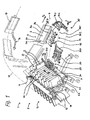
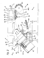
- FIGS. 1 and 2 show a portion of an adhesive binder, consisting of a book block transport system with a plurality of in a closed, oval-shaped orbit in the conveying direction F 3 continuously movable and drivingly hinged to a conveyor chain 4 at equal mutual distances block clamps 3, with a feeder 1 for feeding mainly from single sheets and / or quarter sheet formed sheet stacks, so-called loose book block 2, and an arrow 16 shown by an arrow export 16 for carrying adhesive bound in the booklet booklet 17 or book block.
- a feeder 1 for feeding mainly from single sheets and / or quarter sheet formed sheet stacks, so-called loose book block 2
- an arrow 16 shown by an arrow export 16 for carrying adhesive bound in the booklet booklet 17 or book block.
- the oval-shaped orbit are the various, in the FIGS. 1 and 2 not shown Stations for back processing and gluing and arranged for Umschlag applying and -presseen.
- the block clamps 3 may be parallel closing block clamps, comprising an inner fixed jaw 3 a and a perpendicular to the inner jaw 3 a displaceable outer jaw 3 b, or there are translationally swung block brackets, in which the outer jaw 3 b by means of a Swivel arm to the inner fixed jaw 3 a is movable.
- deflection run open block brackets 3 from the export to a transfer area 22, then taken over by the feeder 1 book block 2 by closing the block brackets 3 and transported further, the block back 2 a by a defined amount down from the block brackets. 3 protrudes.
- the head 2 b of the book block 2 is seen in the conveying direction F 3 behind.
- the adhesive binder can also be a linearly running perfect binder with a clamping plate conveyor of two rotating plate chains, between which the book blocks are clamped and transported at fixed intervals.
- the feeder 1 consists of a separate vibrator 5 for aligning manually applied or via a coupling with upstream machines, such as a gathering machine or a digital printing press, supplied sheet stacks respectively.
- upstream machines such as a gathering machine or a digital printing press
- unbound book block 2 and a clamp carriage conveyor 30 for transferring aligned in the vibrator 5 book block 2 in the block brackets.
- the vibrating device 5 has first and second vibrating plates 6.1, 6.2 attached to vibrating elements 7, which are arranged at right angles to each other and inclined at an angle ⁇ of preferably 45 ° to the horizontal.
- the loose book blocks 2 are with their block back 2a as the first sheet edges on the first vibrating plate 6.1 and lie with second leaf edges, here the head 2 b of the book block 2, on the second vibrating plate 6.2 as an alignment.
- the lateral guidance takes place with guide plates 10.
- the vibrator 5 is designed as a revolving pocket conveyor system 13.
- a plurality of guide plates 10 are coupled to a circulating conveyor chain 18, wherein between each successive guide plates 10, a receiving pocket 14 is present.
- the pocket conveyor system 13 has a conveying direction F 1 .
- Book blocks 2 applied in the area of a manual installation 24 are successively transported to a ready position 21 and in the process undergo a transverse displacement via the vibrating plates 6.1, 6.2.
- the vibrating plates 6.1, 6.2 do not extend over the full length of the vibrating device 5. They end before the provision position 21.
- Rigid plates 8 join with interlocking tongues 8 a and oblique separation points 9 to the vibrating plates 6.1, 6.2 and form a smoothing area 12, in which the aligned book block 2 come to rest, for proper takeover by the Klemmwagen complexityer 30.
- the vibrating plates 6.1, 6.2 may extend into the calming area 12, wherein in the calming area 12 only a small Rüttelintenstician would be present on the one hand reduces the friction in the transverse transport to the ready position 21 and on the other hand allows the acquisition of the aligned book block 2 from a quasi-stationary position out.
- the guide plates 10 are engaged via spring-loaded roller lever 19 driving cams 20 of the conveyor chain 18, whereby a certain distance A 'is defined between the guide plates.
- the guide plates 10 can be disengaged from the conveyor chain 18 and held by adjusting means in certain positions, whereby between the guide plates 10 adapted to the block thickness D distance A "can be adjusted.
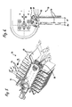
- FIGS. 1 . 2 and 5 is an above the bag conveying system 13 arranged adjusting element 11 can be seen with which a respective front guide plate 10 can be held in the ready position 21, while the subsequent rear guide plate 10 of the controlled according to the block thickness D and the timing of the perfect binder conveyor chain 18 so far on is moved, that the book block 2 is clamped laterally in this receiving pocket 14.
- the guide plates 10 in the ready position 21, from which an aligned book block 2 is removed by means of the clamping carriage conveyor 30, are first held in a narrow, measured according to the block thickness D guide position, then in one of the aligned (single) leaves of the book block. 2 between the two guide plates 10 clamping clamping position and finally after taking over the book block 2 are moved by the clamping carriage conveyor 30 in a release position.
- the front guide plate 10 engages in the conveyor chain 18 again, for return to the area of the handset 24, where new book block 2 can be inserted into the receiving pockets 14.
- the guide plates 10 can also be alternately driven on two separately Be coupled conveyor chains.
- the receiving pockets 14 are then present between the first and the second, between the third and the fourth, etc. guide plate 10, wherein the first, third, etc. guide plate 10 on the first conveyor chain and the second, fourth, etc. guide plate on the second Conveyor chain are coupled.
- phase shifting of the second conveyor chain to the first conveyor chain can then be adjusted in the receiving pockets 14 adapted to the block thickness D distance A '.
- the second vibrating plate 6.2 is adjustable together with the bag conveying system 13 according to the adjustment arrow V H. This ensures that when changing the format height of the book block 2 whose foot 2 c continues to lie in the region of the outer edge of the vibrating plate 6.1 so that the book block 2 can be taken over by the clamping carriage conveyor 30.
- the clamping carriage conveyor 30 has a total of four on an orbit in a conveying direction F 2 successively circulating clamping carriage 31.1 ... 4.
- Fig. 7 a and b consists of each clamping carriage 31.1 ... 4 of mutually hinged, flexible in a first direction and transverse stable in a second direction Klemmwagengliedern 34.
- the individual, corresponding to the Klemmwagengliedern 34 formed clamping portions 36.1 ... 3 can be opened and closed by the operation of control rollers 35 arranged on the underside.
- first clamping bars 33. 1 are also stationary and second clamping bars 33. 2 are arranged displaceably on the clamping carriages 31. It is also possible for both clamping strips 33.1 and 33.2 to be displaceable.
- the opening width of the terminal strips 33.1, 33.2 can be adjusted according to the block thickness D of the book block 2 to be adopted.
- the clamping carriage 31.1 ... 4 then come from below coming through a release 23 in the ready position 21 of the vibrator 5 a.
- the terminal strips 33.1, 33.2 can move in a respective space between the book block 2, which results due to a certain thickness D F of the guide plates 10 and their distance A F of the vibrating plate 6.1.
- a closing device 39 By means of a closing device 39, the individual clamping sections 36.1... 3 are then successively closed.
- the clamping carriage 34.1 ... 4 Provided here is an intermittent drive of the clamping carriage 34.1 ... 4, with a standstill phase in which the first clamping portion 36.1 is closed.
- the respective clamping carriage 31.1... 4 is then clamped with the clamping portion 36.1 clamped by the first clamping portion Book block 2 is preferred at a relatively slow speed, wherein a respective subsequent clamping section 36.2 ... 3 in the conveying movement of the clamping carriage 34.1 ... 4 is closed as soon as it has approached the block back 2 a.
- the clamping carriage 31.1... 4 can be moved in a greatly accelerated movement to the block clamps 3, the book block 2 being introduced from below into the open block clamp 3.
- the block clamp 3 In a synchronous phase in the transfer area 22 with the block clamp 3 running at constant speed, the block clamp 3 is first closed and then the terminal strips 33.1, 33.2 are opened in their entirety via all the clamp sections 36.1. The book blocks 2 are therefore no longer released after the acquisition of the vibrator 5 until they are firmly clamped in the block brackets 3, so-called positive transfer.
- each successive clamping carriage 31.1 and 31.2 or 31.2 and 31.3, etc. coupled to independently driven conveyor chains 38.1, 38.2. Clamping carriage 31.1 and 31.3 on conveyor chain 38.1 and 31.2 and 31.4 clamping carriage on conveyor chain 38.2.
- Fig. 1 a development of the invention by dashed lines 15 is indicated, in which the bag conveyor system 13 is extended to the export 16 of the perfect binder.
- Perfect-binding brochures 17 or book blocks can be dispensed into the receiving pockets 14 and dwell therein for drying and, if necessary, transported to the manual unit 24 of the book block 2 so that a worker can complete both the application of book blocks 2 and the removal of bound booklets 17 ,
Landscapes
- Engineering & Computer Science (AREA)
- Mechanical Engineering (AREA)
- Feeding Of Articles By Means Other Than Belts Or Rollers (AREA)
- Pile Receivers (AREA)
- Collation Of Sheets And Webs (AREA)
Applications Claiming Priority (1)
| Application Number | Priority Date | Filing Date | Title |
|---|---|---|---|
| DE102011018510A DE102011018510A1 (de) | 2011-04-23 | 2011-04-23 | Vorrichtung zum Zuführen von Buchblocks zu einer Buchbindemaschine |
Publications (1)
| Publication Number | Publication Date |
|---|---|
| EP2514603A1 true EP2514603A1 (fr) | 2012-10-24 |
Family
ID=46045673
Family Applications (1)
| Application Number | Title | Priority Date | Filing Date |
|---|---|---|---|
| EP12002764A Withdrawn EP2514603A1 (fr) | 2011-04-23 | 2012-04-20 | Dispositif de transport de blocs de livres vers une machine de reliure de livres |
Country Status (4)
| Country | Link |
|---|---|
| US (1) | US20120267217A1 (fr) |
| EP (1) | EP2514603A1 (fr) |
| JP (1) | JP2012228880A (fr) |
| DE (1) | DE102011018510A1 (fr) |
Cited By (2)
| Publication number | Priority date | Publication date | Assignee | Title |
|---|---|---|---|---|
| CN110077141A (zh) * | 2019-04-22 | 2019-08-02 | 北京汇林印务有限公司 | 一种圆盘胶订机的自动上下料系统 |
| CN110451305A (zh) * | 2019-08-16 | 2019-11-15 | 西安科技大学 | 一种会计凭证自动排序整理机 |
Citations (7)
| Publication number | Priority date | Publication date | Assignee | Title |
|---|---|---|---|---|
| DE3336397A1 (de) * | 1982-10-08 | 1984-05-30 | Kolbus GmbH & Co KG, 4993 Rahden | Vorrichtung zum zufuehren von buchblocks in blockzangen einer klebebindemaschine |
| DE3413222A1 (de) * | 1984-04-07 | 1985-10-17 | Kolbus GmbH & Co KG, 4993 Rahden | Verfahren zum ueberfuehren von buchblocks in das transportmittel einer buchbindemaschine und vorrichtung zur durchfuehrung des verfahrens |
| EP0194461A2 (fr) * | 1985-03-08 | 1986-09-17 | Kolbus GmbH & Co. KG | Dispositif déchargeur pour machine à relier par adhésif |
| EP0712736A2 (fr) * | 1994-11-18 | 1996-05-22 | Grapha-Holding Ag | Méthode pour la fabrication de livres, brochures ou similaires reliés par adhésif |
| DE202005007012U1 (de) | 2005-05-02 | 2005-08-04 | Kolbus Gmbh & Co. Kg | Buchbindemaschine |
| EP1886833A1 (fr) * | 2006-08-10 | 2008-02-13 | Müller Martini Holding AG | Procédé et dispositif de fabrication d'un objet imprimé relié par adhésif à partir de plusieurs produits imprimés |
| EP1347864B1 (fr) * | 2000-12-08 | 2010-07-21 | Jeffrey D. Marsh | Appareil et procede d'impression, reliure et rognage, sur demande, d'un livre relie sans couture |
Family Cites Families (2)
| Publication number | Priority date | Publication date | Assignee | Title |
|---|---|---|---|---|
| US5073801A (en) * | 1989-08-09 | 1991-12-17 | Konica Corporation | Color image forming apparatus having different ejection parts for different paper thickness |
| US6685416B2 (en) * | 2001-07-11 | 2004-02-03 | Dynic Corporation | Bookbinding device and method |
-
2011
- 2011-04-23 DE DE102011018510A patent/DE102011018510A1/de not_active Withdrawn
-
2012
- 2012-04-20 US US13/452,024 patent/US20120267217A1/en not_active Abandoned
- 2012-04-20 EP EP12002764A patent/EP2514603A1/fr not_active Withdrawn
- 2012-04-23 JP JP2012097727A patent/JP2012228880A/ja active Pending
Patent Citations (7)
| Publication number | Priority date | Publication date | Assignee | Title |
|---|---|---|---|---|
| DE3336397A1 (de) * | 1982-10-08 | 1984-05-30 | Kolbus GmbH & Co KG, 4993 Rahden | Vorrichtung zum zufuehren von buchblocks in blockzangen einer klebebindemaschine |
| DE3413222A1 (de) * | 1984-04-07 | 1985-10-17 | Kolbus GmbH & Co KG, 4993 Rahden | Verfahren zum ueberfuehren von buchblocks in das transportmittel einer buchbindemaschine und vorrichtung zur durchfuehrung des verfahrens |
| EP0194461A2 (fr) * | 1985-03-08 | 1986-09-17 | Kolbus GmbH & Co. KG | Dispositif déchargeur pour machine à relier par adhésif |
| EP0712736A2 (fr) * | 1994-11-18 | 1996-05-22 | Grapha-Holding Ag | Méthode pour la fabrication de livres, brochures ou similaires reliés par adhésif |
| EP1347864B1 (fr) * | 2000-12-08 | 2010-07-21 | Jeffrey D. Marsh | Appareil et procede d'impression, reliure et rognage, sur demande, d'un livre relie sans couture |
| DE202005007012U1 (de) | 2005-05-02 | 2005-08-04 | Kolbus Gmbh & Co. Kg | Buchbindemaschine |
| EP1886833A1 (fr) * | 2006-08-10 | 2008-02-13 | Müller Martini Holding AG | Procédé et dispositif de fabrication d'un objet imprimé relié par adhésif à partir de plusieurs produits imprimés |
Non-Patent Citations (2)
| Title |
|---|
| "Fachartikel Ober 4.000 Produkte am Tag: Klebebindung im Akkord mit Roberto", DEUTSCHER DRUCKER, 19 August 2000 (2000-08-19), pages 25 |
| "Über 4.000 Produkte am Tag: Klebebindung im Akkord mit Roberto", DEUTSCHER DRUCKER, DEUTSCHER DRUCKER VERLAGSGESELLSCHAFT, OSTFILDERN, DE, vol. 26, 19 August 2000 (2000-08-19), pages 25, XP009161056, ISSN: 0012-1096 * |
Cited By (3)
| Publication number | Priority date | Publication date | Assignee | Title |
|---|---|---|---|---|
| CN110077141A (zh) * | 2019-04-22 | 2019-08-02 | 北京汇林印务有限公司 | 一种圆盘胶订机的自动上下料系统 |
| CN110451305A (zh) * | 2019-08-16 | 2019-11-15 | 西安科技大学 | 一种会计凭证自动排序整理机 |
| CN110451305B (zh) * | 2019-08-16 | 2020-10-09 | 西安科技大学 | 一种会计凭证自动排序整理机 |
Also Published As
| Publication number | Publication date |
|---|---|
| US20120267217A1 (en) | 2012-10-25 |
| JP2012228880A (ja) | 2012-11-22 |
| DE102011018510A1 (de) | 2012-10-25 |
Similar Documents
| Publication | Publication Date | Title |
|---|---|---|
| DE102012003604B4 (de) | Vorrichtung zum Zuführen von Buchblocks in den Einfuhrkanal einer Weiterverarbeitungseinrichtung | |
| DE102012003602B4 (de) | Vorrichtung zum Zuführen von Buchblocks in den Einfuhrkanal einer Weiterverarbeitungseinrichhtung | |
| EP0476718B1 (fr) | Dispositif pour piquer des produits d'imprimerie à plusieurs parties | |
| EP0675005B1 (fr) | Dispositif pour la reliure adhésive de produits imprimés | |
| CH667621A5 (de) | Sammelhefter. | |
| EP1690696A1 (fr) | Dispositif et procédé pour l'endossage mécanique des signatures | |
| EP1153872B1 (fr) | Dispositif et méthode pour préparer le dos d'un livre pour la reliure | |
| DE3413222C2 (de) | Verfahren zum Überführen von Buchblocks in das Transportmittel einer Buchbindemaschine und Vorrichtung zur Durchführung des Verfahrens | |
| DE2630161C3 (de) | Verfahren und Vorrichtung zur Herstellung von gehefteten Büchern | |
| EP0712736B1 (fr) | Méthode pour la fabrication de livres, brochures ou similaires reliés par adhésif | |
| EP1674285B1 (fr) | Machine pour former et pincer des livres | |
| EP1528023B1 (fr) | Méthode et dispositif pour changer un flux d'articles plats | |
| EP2455227B1 (fr) | Machine de reliure avec dispositif d'application de couverture | |
| CH695556A5 (de) | Verfahren zum maschinellen Heften von mehrlagigen Druckereiprodukten mittels Drahtklammern und Vorrichtung zur Durchführung des Verfahrens. | |
| EP2514604A1 (fr) | Dispositif de transport de blocs de livres vers une machine de reliure de livres | |
| EP2514603A1 (fr) | Dispositif de transport de blocs de livres vers une machine de reliure de livres | |
| DE1561141B2 (de) | Vorrichtung zum einfuehren von beilagen in gefaltete druckerzeugnisse | |
| EP2030801B1 (fr) | Procédé pour la reliure par adhésif de produits imprimés pour la production d'un ouvrage imprimé et dispositif correspondant | |
| EP3290223B1 (fr) | Dispositif et procédé d'alignement d'un bloc-livre comprenant des feuilles individuelles et/ou des cahiers | |
| EP1655148B1 (fr) | Dispositif pour la reliure par adhésif de produits imprimés pour la production d'un ouvrage imprimé | |
| DE2220567A1 (de) | Verfahren und vorrichtung zum buchbinden | |
| DE3419610A1 (de) | Verfahren und vorrichtung zum anbringen von deckblaettern an bloecken | |
| DE102014002506A1 (de) | Klebebinderklammer | |
| DE3100866A1 (de) | Maschine zum transportieren einer folge von buechern | |
| DE10115493A1 (de) | Vorrichtung und Verfahren zur Bereitstellung eines Einbandes für ein Buch |
Legal Events
| Date | Code | Title | Description |
|---|---|---|---|
| PUAI | Public reference made under article 153(3) epc to a published international application that has entered the european phase |
Free format text: ORIGINAL CODE: 0009012 |
|
| AK | Designated contracting states |
Kind code of ref document: A1 Designated state(s): AL AT BE BG CH CY CZ DE DK EE ES FI FR GB GR HR HU IE IS IT LI LT LU LV MC MK MT NL NO PL PT RO RS SE SI SK SM TR |
|
| AX | Request for extension of the european patent |
Extension state: BA ME |
|
| STAA | Information on the status of an ep patent application or granted ep patent |
Free format text: STATUS: THE APPLICATION IS DEEMED TO BE WITHDRAWN |
|
| 18D | Application deemed to be withdrawn |
Effective date: 20130425 |