EP0713351A1 - Induktions Kochmulde - Google Patents
Induktions Kochmulde Download PDFInfo
- Publication number
- EP0713351A1 EP0713351A1 EP95402525A EP95402525A EP0713351A1 EP 0713351 A1 EP0713351 A1 EP 0713351A1 EP 95402525 A EP95402525 A EP 95402525A EP 95402525 A EP95402525 A EP 95402525A EP 0713351 A1 EP0713351 A1 EP 0713351A1
- Authority
- EP
- European Patent Office
- Prior art keywords
- support
- inductor
- induction cooking
- cooking hearth
- hearth according
- Prior art date
- Legal status (The legal status is an assumption and is not a legal conclusion. Google has not performed a legal analysis and makes no representation as to the accuracy of the status listed.)
- Granted
Links
- 230000006698 induction Effects 0.000 title claims abstract description 24
- 238000010411 cooking Methods 0.000 title claims description 26
- 229910000859 α-Fe Inorganic materials 0.000 claims abstract description 5
- 239000012777 electrically insulating material Substances 0.000 claims abstract description 4
- 239000000463 material Substances 0.000 claims description 7
- 239000004020 conductor Substances 0.000 claims description 6
- 239000000696 magnetic material Substances 0.000 claims description 6
- CPLXHLVBOLITMK-UHFFFAOYSA-N Magnesium oxide Chemical compound [Mg]=O CPLXHLVBOLITMK-UHFFFAOYSA-N 0.000 claims description 4
- 239000000843 powder Substances 0.000 claims description 3
- 239000004568 cement Substances 0.000 claims description 2
- 239000000395 magnesium oxide Substances 0.000 claims description 2
- 239000002245 particle Substances 0.000 claims description 2
- 238000000465 moulding Methods 0.000 claims 1
- 239000002241 glass-ceramic Substances 0.000 abstract description 2
- 238000009413 insulation Methods 0.000 abstract description 2
- 230000004907 flux Effects 0.000 abstract 1
- 230000008901 benefit Effects 0.000 description 4
- 238000004519 manufacturing process Methods 0.000 description 3
- 238000004804 winding Methods 0.000 description 3
- 239000012212 insulator Substances 0.000 description 2
- 238000013021 overheating Methods 0.000 description 2
- RYGMFSIKBFXOCR-UHFFFAOYSA-N Copper Chemical compound [Cu] RYGMFSIKBFXOCR-UHFFFAOYSA-N 0.000 description 1
- XEEYBQQBJWHFJM-UHFFFAOYSA-N Iron Chemical compound [Fe] XEEYBQQBJWHFJM-UHFFFAOYSA-N 0.000 description 1
- XAGFODPZIPBFFR-UHFFFAOYSA-N aluminium Chemical compound [Al] XAGFODPZIPBFFR-UHFFFAOYSA-N 0.000 description 1
- 229910052782 aluminium Inorganic materials 0.000 description 1
- 230000009286 beneficial effect Effects 0.000 description 1
- 239000000919 ceramic Substances 0.000 description 1
- 229910052802 copper Inorganic materials 0.000 description 1
- 239000010949 copper Substances 0.000 description 1
- 230000002500 effect on skin Effects 0.000 description 1
- 238000010292 electrical insulation Methods 0.000 description 1
- 230000005284 excitation Effects 0.000 description 1
- 239000011491 glass wool Substances 0.000 description 1
- 238000010438 heat treatment Methods 0.000 description 1
- 230000001939 inductive effect Effects 0.000 description 1
- 239000000615 nonconductor Substances 0.000 description 1
- 230000003071 parasitic effect Effects 0.000 description 1
- 230000005855 radiation Effects 0.000 description 1
Images
Classifications
-
- H—ELECTRICITY
- H05—ELECTRIC TECHNIQUES NOT OTHERWISE PROVIDED FOR
- H05B—ELECTRIC HEATING; ELECTRIC LIGHT SOURCES NOT OTHERWISE PROVIDED FOR; CIRCUIT ARRANGEMENTS FOR ELECTRIC LIGHT SOURCES, IN GENERAL
- H05B6/00—Heating by electric, magnetic or electromagnetic fields
- H05B6/02—Induction heating
- H05B6/10—Induction heating apparatus, other than furnaces, for specific applications
- H05B6/12—Cooking devices
- H05B6/1209—Cooking devices induction cooking plates or the like and devices to be used in combination with them
- H05B6/1245—Cooking devices induction cooking plates or the like and devices to be used in combination with them with special coil arrangements
- H05B6/1254—Cooking devices induction cooking plates or the like and devices to be used in combination with them with special coil arrangements using conductive pieces to direct the induced magnetic field
-
- H—ELECTRICITY
- H05—ELECTRIC TECHNIQUES NOT OTHERWISE PROVIDED FOR
- H05B—ELECTRIC HEATING; ELECTRIC LIGHT SOURCES NOT OTHERWISE PROVIDED FOR; CIRCUIT ARRANGEMENTS FOR ELECTRIC LIGHT SOURCES, IN GENERAL
- H05B6/00—Heating by electric, magnetic or electromagnetic fields
- H05B6/02—Induction heating
- H05B6/10—Induction heating apparatus, other than furnaces, for specific applications
- H05B6/12—Cooking devices
- H05B6/1209—Cooking devices induction cooking plates or the like and devices to be used in combination with them
- H05B6/1245—Cooking devices induction cooking plates or the like and devices to be used in combination with them with special coil arrangements
- H05B6/1281—Cooking devices induction cooking plates or the like and devices to be used in combination with them with special coil arrangements with flat coils
-
- H—ELECTRICITY
- H05—ELECTRIC TECHNIQUES NOT OTHERWISE PROVIDED FOR
- H05B—ELECTRIC HEATING; ELECTRIC LIGHT SOURCES NOT OTHERWISE PROVIDED FOR; CIRCUIT ARRANGEMENTS FOR ELECTRIC LIGHT SOURCES, IN GENERAL
- H05B2206/00—Aspects relating to heating by electric, magnetic, or electromagnetic fields covered by group H05B6/00
- H05B2206/02—Induction heating
- H05B2206/022—Special supports for the induction coils
-
- Y—GENERAL TAGGING OF NEW TECHNOLOGICAL DEVELOPMENTS; GENERAL TAGGING OF CROSS-SECTIONAL TECHNOLOGIES SPANNING OVER SEVERAL SECTIONS OF THE IPC; TECHNICAL SUBJECTS COVERED BY FORMER USPC CROSS-REFERENCE ART COLLECTIONS [XRACs] AND DIGESTS
- Y02—TECHNOLOGIES OR APPLICATIONS FOR MITIGATION OR ADAPTATION AGAINST CLIMATE CHANGE
- Y02B—CLIMATE CHANGE MITIGATION TECHNOLOGIES RELATED TO BUILDINGS, e.g. HOUSING, HOUSE APPLIANCES OR RELATED END-USER APPLICATIONS
- Y02B40/00—Technologies aiming at improving the efficiency of home appliances, e.g. induction cooking or efficient technologies for refrigerators, freezers or dish washers
Definitions
- the present invention relates to an improvement in induction cooking appliances.
- the general principle of induction cooking consists of placing a container suitable for this type of cooking above an inductor supplied by a high frequency electric current.
- the magnetic field produced by the inductor generates, by induction, a circulation of currents in the walls and the bottom of the container, which will heat up and allow, by thermal conduction, the heating and cooking of a food placed in the container.
- the inductor is conventionally constituted by at least one flat coil, produced by winding a strand of son on itself in the form of a spiral, generally circular and concentric.
- the current supply in the coil is effected by connecting the two free ends of the strand, one being in the center of the spiral and the other, on the periphery, at the terminals of a generator delivering a high frequency current.
- the strands of wires generally made of copper, used for the known inductors have a large section, typically of the order of 6 mm.
- This strong section has a beneficial effect on the distribution and evacuation of losses from the inductor winding, the temperature of which should not exceed 200 ° C for standard insulation of elementary wires.
- this important section has a significant impact on the overall cost of an inductor.
- the main object of the present invention is to provide an induction cooking hearth in which the inductor used has a constant diameter, produced from a strand whose cross section is considerably reduced compared to known inductors. This requires removing heat which becomes more difficult to transport due to the smaller section of the strand.
- an induction cooking hearth comprising an inductive winding in rigid flat arranged vertically in a spiral groove hollowed out on the surface of a support.
- This cooking zone is only suitable for low power due to the problems of the skin effect and proximity of the load which cause the current to migrate to the upper surface of the flat.
- the useful volume through which the high frequency currents pass is strongly located at the top of the conductor and very reduced, which results in overheating, limiting the application of this device to currents and therefore low excitation powers.
- This hearth also poses the problem of maintaining the rigid conductive wire in its housing for which it is necessary to provide fixing lugs which are difficult to produce in a material which must be both electrical insulator and heat resistant.
- the present invention relates to an induction cooking hearth of the type described in document US-A-4,467,162, characterized in that the support is made of a thermally conductive and electrically insulating material and in that, the inductor comprising a strand of multi-strand electrically conductive wires wound in the form of a spiral, the support comprises, on its upper face, at least one spiral-shaped housing adapted to receive said strand, so as to optimize the heat transfer between the inductor and shielding plate.
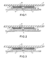
- FIGS. 1, 2 and 3 schematically represent, in section along a vertical plane, possible variants an induction cooking stove according to the invention.
- the induction cooking hearth shown in FIGS. 1 and 2 conventionally comprises an inductor formed by a strand 1 of wires electrical conductors wound in a spiral shape.
- the cuts made in the figures show the different turns 10 of the inductor.
- the inductor is placed under a plate 2, for example made of glass ceramic, intended to receive the containers to be heated.
- the inductor is preferably separated from the plate by a layer 2a of thermal insulator (ceramic paper or glass wool) so as to protect the inductor from overheating of the containers.
- the hearth also comprises, in known manner, an inductor support 3 comprising a magnetic material whose role is to focus the magnetic field created by the inductor towards the container to be heated, and a plate 4 made of non-magnetic material, for example in aluminum, the role of which is to minimize the stray fields of the inductor, with a view in particular to protecting the electronic devices (not shown) used to control the hearth.
- the shielding plate 4 is in contact with the underside of the support 3.
- the support 3 has in its center an opening 5 corresponding to the center of the inductor, and in particular allowing passage a temperature sensor (not shown) for cooking control.
- the support 3 is made of a thermal conductive and electrically insulating material so as to allow heat transfer from the inductor 1 to the plate 4.
- the latter can thus evacuate the excess heat harmful to the inductor.
- the thermal conductivity of the material chosen is typically between 0.8 and 2 W.m ⁇ 1.K ⁇ 1, the materials usually used having a thermal conductivity of the order of 0.3 W.m ⁇ 1.K ⁇ 1.
- the heat transfer is optimized by placing each turn 10 of the inductor in a housing 30 in the form of a spiral provided on the upper face of the support.
- Each turn 10 is thus in contact with the support on a circular portion and no longer at a single point as occurs when the inductor is simply placed on the flat upper face of a support.
- the housing 30 can be produced by printing a spiral on the upper face of the support. Another possibility is to directly mold the support with its housing, or to overmold the inductor in its support.
- the first advantage which results directly from the improvement in heat transfer, is that it is now possible to significantly reduce the section of the strand, for a level of high frequency losses comparable to that of a conventional strand.
- the size of the housing accommodating the various turns makes it possible to calibrate the diameter of the inductor very precisely.
- the housing can allow electrical insulation between two consecutive turns.
- inductor all the shapes you want (contiguous turns or not, inductor in the shape of a circular, elliptical or other spiral). It suffices to provide, for the support, a housing of suitable shape.
- the same support can comprise several housings, each housing being adapted to a particular form of inductor. In this way, the choice of the inductor which will actually take place in one of the housings can be made at the time of assembly.
- the inductor support 3 conventionally comprises slots, for example radial, inside which bars 31 made of magnetic material, for example ferrite, are arranged.
- the support may in particular be made of plastic loaded with thermally conductive particles, or of refractory cement based on magnesia powder.
- the material chosen for the support allows the latter to serve simultaneously as a magnetic circuit refocusing the magnetic field lines on the top of the inductor and as a means of evacuating the heat towards the plate. shielding 4.
- the support it is possible for example to produce the support with ferrite and / or iron powder, bound for example by a plastic.
- the plate 4 which serves, in a conventional manner, for shielding parasitic radiation from the inductor and, according to the invention, for means of dissipating heat energy, can advantageously be dimensioned to also serve as a support for the assembly consisting of the inductor and the inductor support.
- the section of the strand can be reduced up to 2.5 mm, the housing can have a slightly greater width to accommodate this strand, and a depth of about 3 mm.
- the plate 4 can also be circular, and preferably has a thickness substantially equal to 1.2 mm.
- connection between the plate 4 and the support 3 must allow good heat transfer. This can be achieved by bonding the support to the tray, by overmolding or even by simple pressure.
- the shape of the imprint can be, as shown in Figure 3, such that if the strand is forced into the imprint it does not come out. In this case, the width of the cavity must be less than the diameter of the strand which is compressed before being pushed into the cavity. This can allow the use of a standard base wire knowing that most of the other principles require the use of a thermoadherent wire.
- the plate 4 advantageously has holes. During the overmolding operation, part of the material used for the support passes through these holes and comes to spread around this hole, thus forming a kind of plug holding the support and the plate.
- the holes are preferably arranged on the surface of the plate 4 so as to homogenize the distribution of the currents induced in the plate 4, and thus perfect the heat transfer of the assembly.
- the diameter and the number of holes must be established so as not to penalize the role of electromagnetic screen of the plate.
Landscapes
- Physics & Mathematics (AREA)
- Electromagnetism (AREA)
- Cookers (AREA)
- General Induction Heating (AREA)
- Shielding Devices Or Components To Electric Or Magnetic Fields (AREA)
Applications Claiming Priority (2)
| Application Number | Priority Date | Filing Date | Title |
|---|---|---|---|
| FR9413653 | 1994-11-15 | ||
| FR9413653A FR2726963B1 (fr) | 1994-11-15 | 1994-11-15 | Foyer de cuisson a induction |
Publications (2)
| Publication Number | Publication Date |
|---|---|
| EP0713351A1 true EP0713351A1 (de) | 1996-05-22 |
| EP0713351B1 EP0713351B1 (de) | 1999-10-06 |
Family
ID=9468805
Family Applications (1)
| Application Number | Title | Priority Date | Filing Date |
|---|---|---|---|
| EP95402525A Expired - Lifetime EP0713351B1 (de) | 1994-11-15 | 1995-11-10 | Induktions-Kochmulde |
Country Status (4)
| Country | Link |
|---|---|
| US (1) | US5686006A (de) |
| EP (1) | EP0713351B1 (de) |
| DE (1) | DE69512605T2 (de) |
| FR (1) | FR2726963B1 (de) |
Cited By (4)
| Publication number | Priority date | Publication date | Assignee | Title |
|---|---|---|---|---|
| DE102006038370A1 (de) * | 2006-08-11 | 2008-02-14 | E.G.O. Elektro-Gerätebau GmbH | Spulenträger für Induktoren |
| FR2965446A1 (fr) * | 2010-09-23 | 2012-03-30 | Jaeger | Inducteur ameliore |
| US20230016441A1 (en) * | 2020-01-31 | 2023-01-19 | BSH Hausgeräte GmbH | Induction cooking device |
| WO2024200459A1 (fr) * | 2023-03-30 | 2024-10-03 | Adventys | Dispositif de chauffe par induction presentant une repartition de chauffe homogene |
Families Citing this family (41)
| Publication number | Priority date | Publication date | Assignee | Title |
|---|---|---|---|---|
| FR2748885B1 (fr) * | 1996-05-14 | 1998-08-14 | Europ Equip Menager | Foyer de cuisson par induction a rendement eleve |
| DE19845844A1 (de) * | 1998-10-05 | 2000-04-06 | Bsh Bosch Siemens Hausgeraete | Induktor für ein Induktions-Kochfeld |
| DE10122337B4 (de) * | 2001-05-08 | 2006-04-13 | Schott Ag | Wasserkocher aus Glas mit induktiver Heizung |
| US6956188B2 (en) * | 2002-12-06 | 2005-10-18 | General Electric Company | Induction heating coil with integrated resonant capacitor and method of fabrication thereof, and induction heating system employing the same |
| DE102004007729B4 (de) * | 2004-02-16 | 2008-08-21 | Döhler & Gerweck Entwicklungs- und Montagetechnik GmbH | Regalboden für Lebensmittelbehälter |
| DE102005005526A1 (de) * | 2005-01-31 | 2006-08-24 | E.G.O. Elektro-Gerätebau GmbH | Träger für eine Induktionsspule, Induktionsheizeinrichtung, Induktionskochfeld und Verfahren zum Herstellen einer Induktionsheizeinrichtung |
| FR2895638B1 (fr) * | 2005-12-27 | 2008-04-18 | Brandt Ind Sas | Dispositif inducteur a bobinages individuels multiples pour foyer de cuisson par induction |
| WO2011020720A1 (de) * | 2009-08-17 | 2011-02-24 | BSH Bosch und Siemens Hausgeräte GmbH | Induktiv beheiztes kochfeld mit einer metallisch beschichteten abdeckplatte |
| JP5671470B2 (ja) * | 2009-10-23 | 2015-02-18 | パナソニックIpマネジメント株式会社 | 誘導加熱装置 |
| FR2994050B1 (fr) * | 2012-07-26 | 2016-03-04 | Fagorbrandt Sas | Nappe de materiau isolant pour inducteurs d'un appareil de cuisson a induction et appareil de cuisson a induction associe |
| CN102813454A (zh) * | 2012-08-28 | 2012-12-12 | 淮南联合大学 | 电磁加热安全节能煮面机 |
| WO2014056786A1 (en) * | 2012-10-11 | 2014-04-17 | Arcelik Anonim Sirketi | A wireless cooking appliance operated on an induction heating cooktop |
| ITTO20120896A1 (it) | 2012-10-15 | 2014-04-16 | Indesit Co Spa | Piano cottura a induzione |
| US10605464B2 (en) | 2012-10-15 | 2020-03-31 | Whirlpool Corporation | Induction cooktop |
| US10645763B2 (en) | 2013-02-19 | 2020-05-05 | Illinois Tool Works Inc. | Induction heating head |
| ITTO20130430A1 (it) | 2013-05-28 | 2014-11-29 | Illinois Tool Works | Dispositivo per il pre-riscaldamento ad induzione e la saldatura testa a testa di lembi adiacenti di almeno un elemento da saldare |
| CN103415100A (zh) * | 2013-08-28 | 2013-11-27 | 段伟 | 一种磁聚环加热装置 |
| EP2916432A1 (de) * | 2014-03-06 | 2015-09-09 | Electrolux Appliances Aktiebolag | Elektrische Vorrichtung |
| US11510290B2 (en) | 2014-05-16 | 2022-11-22 | Illinois Tool Works Inc. | Induction heating system |
| US9913320B2 (en) | 2014-05-16 | 2018-03-06 | Illinois Tool Works Inc. | Induction heating system travel sensor assembly |
| US10863591B2 (en) | 2014-05-16 | 2020-12-08 | Illinois Tool Works Inc. | Induction heating stand assembly |
| US11076454B2 (en) | 2014-05-16 | 2021-07-27 | Illinois Tool Works Inc. | Induction heating system temperature sensor assembly |
| US11197350B2 (en) | 2014-05-16 | 2021-12-07 | Illinois Tool Works Inc. | Induction heating system connection box |
| FR3033974B1 (fr) * | 2015-03-16 | 2018-11-09 | Chopin Technologies | Dispositif de chauffage, systeme de test comprenant un tel dispositif et procede de mise en œuvre d'un systeme de test. |
| CN107531899A (zh) | 2015-04-28 | 2018-01-02 | 罗门哈斯电子材料有限责任公司 | 作为电镀浴添加剂的胺单体与含有饱和杂环部分的聚合物的反应产物 |
| EP3094159B1 (de) * | 2015-05-14 | 2018-03-28 | Whirlpool Corporation | Induktionskochfeld |
| US11665790B2 (en) * | 2016-12-22 | 2023-05-30 | Whirlpool Corporation | Induction burner element having a plurality of single piece frames |
| EP3432682B1 (de) | 2017-07-18 | 2026-04-08 | Whirlpool Corporation | Verfahren zum betreiben eines induktionskochfelds und kochfeld mit diesem verfahren |
| CN109407568B (zh) * | 2017-08-16 | 2022-03-25 | 佛山市顺德区美的电热电器制造有限公司 | 烹饪器具、烹饪控制方法及计算机装置 |
| US10993292B2 (en) | 2017-10-23 | 2021-04-27 | Whirlpool Corporation | System and method for tuning an induction circuit |
| ES2712662A1 (es) * | 2017-11-14 | 2019-05-14 | Bsh Electrodomesticos Espana Sa | Dispositivo de aparato de cocción por inducción |
| EP3544374B1 (de) | 2018-03-23 | 2020-09-23 | Whirlpool Corporation | Induktionskochfeld mit verbesserter magnetflusskonzentrationsfolie |
| EP3544377B1 (de) | 2018-03-23 | 2020-08-05 | Whirlpool Corporation | Temperaturfühler-kompressionsmerkmale für induktionskochfeldanordnung |
| EP3544375B1 (de) | 2018-03-23 | 2024-05-08 | Whirlpool Corporation | Induktionsspulen-kompressionsvorrichtung für strahlanordnung |
| EP3544376B1 (de) | 2018-03-23 | 2020-08-26 | Whirlpool Corporation | Verbindungsschnittstelle für induktionsspulenarray |
| US12588112B2 (en) | 2018-04-23 | 2026-03-24 | Whirlpool Corporation | System and method for controlling induction heating devices with series connected switching devices |
| US11140751B2 (en) | 2018-04-23 | 2021-10-05 | Whirlpool Corporation | System and method for controlling quasi-resonant induction heating devices |
| US12302478B2 (en) | 2018-04-23 | 2025-05-13 | Whirlpool Corporation | Control circuits and methods for distributed induction heating devices |
| KR20210107487A (ko) * | 2020-02-24 | 2021-09-01 | 엘지전자 주식회사 | 조리기기 |
| BE1028804B1 (nl) * | 2020-11-16 | 2022-06-13 | Novy Int Nv | Een inductiekookinrichting en een kooksamenstel dat deze omvat |
| US20250254765A1 (en) * | 2024-02-07 | 2025-08-07 | Whirlpool Corporation | Insulator for induction appliance |
Citations (6)
| Publication number | Priority date | Publication date | Assignee | Title |
|---|---|---|---|---|
| US4467162A (en) | 1980-06-13 | 1984-08-21 | Riccar Co., Ltd. | Exciting arrangement for induction heating process |
| EP0158353A2 (de) * | 1984-04-11 | 1985-10-16 | TDK Corporation | Kalte Elektrokochplatte |
| US4770355A (en) * | 1985-12-07 | 1988-09-13 | Sumitomo Electric Industries, Ltd. | Methods for manufacturing heating coil assembly |
| JPH01239791A (ja) * | 1988-03-17 | 1989-09-25 | Fuji Electric Co Ltd | 電磁調理器の誘導加熱装置 |
| FR2659725A1 (fr) * | 1990-03-13 | 1991-09-20 | Europ Equip Menager | Appareil de cuisson a induction. |
| EP0565186A2 (de) | 1992-04-10 | 1993-10-13 | Balay, S.A. | Induktive Heizung für elektrische Kochplatte |
Family Cites Families (2)
| Publication number | Priority date | Publication date | Assignee | Title |
|---|---|---|---|---|
| US4029926A (en) * | 1974-10-29 | 1977-06-14 | Roper Corporation | Work coil for use in an induction cooking appliance |
| JP3291751B2 (ja) * | 1992-03-06 | 2002-06-10 | 松下電器産業株式会社 | 誘導加熱調理器 |
-
1994
- 1994-11-15 FR FR9413653A patent/FR2726963B1/fr not_active Expired - Fee Related
-
1995
- 1995-11-10 DE DE69512605T patent/DE69512605T2/de not_active Expired - Fee Related
- 1995-11-10 EP EP95402525A patent/EP0713351B1/de not_active Expired - Lifetime
- 1995-11-15 US US08/559,046 patent/US5686006A/en not_active Expired - Lifetime
Patent Citations (6)
| Publication number | Priority date | Publication date | Assignee | Title |
|---|---|---|---|---|
| US4467162A (en) | 1980-06-13 | 1984-08-21 | Riccar Co., Ltd. | Exciting arrangement for induction heating process |
| EP0158353A2 (de) * | 1984-04-11 | 1985-10-16 | TDK Corporation | Kalte Elektrokochplatte |
| US4770355A (en) * | 1985-12-07 | 1988-09-13 | Sumitomo Electric Industries, Ltd. | Methods for manufacturing heating coil assembly |
| JPH01239791A (ja) * | 1988-03-17 | 1989-09-25 | Fuji Electric Co Ltd | 電磁調理器の誘導加熱装置 |
| FR2659725A1 (fr) * | 1990-03-13 | 1991-09-20 | Europ Equip Menager | Appareil de cuisson a induction. |
| EP0565186A2 (de) | 1992-04-10 | 1993-10-13 | Balay, S.A. | Induktive Heizung für elektrische Kochplatte |
Non-Patent Citations (1)
| Title |
|---|
| PATENT ABSTRACTS OF JAPAN vol. 013, no. 571 (E - 862) 18 December 1989 (1989-12-18) * |
Cited By (6)
| Publication number | Priority date | Publication date | Assignee | Title |
|---|---|---|---|---|
| DE102006038370A1 (de) * | 2006-08-11 | 2008-02-14 | E.G.O. Elektro-Gerätebau GmbH | Spulenträger für Induktoren |
| WO2008017373A1 (de) * | 2006-08-11 | 2008-02-14 | E.G.O. Elektro-Gerätebau GmbH | Spulenträger für induktoren |
| FR2965446A1 (fr) * | 2010-09-23 | 2012-03-30 | Jaeger | Inducteur ameliore |
| US20230016441A1 (en) * | 2020-01-31 | 2023-01-19 | BSH Hausgeräte GmbH | Induction cooking device |
| WO2024200459A1 (fr) * | 2023-03-30 | 2024-10-03 | Adventys | Dispositif de chauffe par induction presentant une repartition de chauffe homogene |
| FR3147477A1 (fr) * | 2023-03-30 | 2024-10-04 | Adventys | Dispositif de chauffe par induction presentant une repartition de chauffe homogene |
Also Published As
| Publication number | Publication date |
|---|---|
| FR2726963B1 (fr) | 1996-12-06 |
| DE69512605T2 (de) | 2000-05-25 |
| DE69512605D1 (de) | 1999-11-11 |
| EP0713351B1 (de) | 1999-10-06 |
| US5686006A (en) | 1997-11-11 |
| FR2726963A1 (fr) | 1996-05-15 |
Similar Documents
| Publication | Publication Date | Title |
|---|---|---|
| EP0713351B1 (de) | Induktions-Kochmulde | |
| BE1013307A3 (fr) | Foyer de cuisson par induction modulable a rayonnement reduit et procede de realisation. | |
| EP0808080B1 (de) | Hocheffiziente Induktionskochstelle | |
| EP0462011B1 (de) | Induktionsheizspule | |
| EP1575336B1 (de) | Zusammensetzungsmodul von Induktionsspulen einer Induktionskochzone und Kochzone ausgestattet mit solchem Modul | |
| FR2475191A1 (fr) | Ensemble chauffant a rayonnement pour cuisinieres a plaque de cuisson lisse | |
| JPH06251753A (ja) | 無電極高圧放電ランプ | |
| EP0772955B1 (de) | Induktor und verfahren zur herstellung eines induktors | |
| FR2487620A1 (fr) | Dispositif chauffant electrique pour une table de cuisson en vitroceramique | |
| EP3056070B1 (de) | Elektrisches modul, elektrischen system mit derartigem elektrischen modul und zugehörige herstellungsverfahren | |
| FR2624645A1 (fr) | Transformateur a haute frequence pour four a micro-onde | |
| FR2971910A1 (fr) | Foyer de cuisson a induction et table de cuisson a induction associee | |
| EP1967045B1 (de) | Induktorsvorrichtung versehen mit einzigen mehrwicklungen für induktiven kochfelden | |
| EP1792526A1 (de) | Mit integriertem wärmeverteiler ausgestattete elektronische einrichtung | |
| FR2971909A1 (fr) | Table de cuisson a induction comprenant un foyer de cuisson a induction | |
| CA1311019C (fr) | Four pour le traitement thermo-magnetique de bobines toroidales | |
| EP0771135B1 (de) | Aus Litzenleitern induktive Wicklung eines Induktionskochgerätes | |
| FR2631486A1 (fr) | Lampe a decharge de haute intensite sabs electrodes | |
| FR2763116A1 (fr) | Foyer de cuisson a detection de la presence d'un recipient | |
| EP1203511B1 (de) | Induktions-infrarotsender und seine verwendungen | |
| FR3006425A1 (fr) | Dispositif de chauffage par induction et table de cuisson a induction associee | |
| FR2926946A1 (fr) | Appareil de cuisson par induction. | |
| EP0365407B1 (de) | Leistungstransformator mit reduzierter Erhitzung | |
| EP3064916A1 (de) | Temperaturmessgerät, insbesondere für kochherd | |
| FR2597261A1 (fr) | Boitier d'encapsulation de circuits integres a dissipation thermique amelioree, et procede de fabrication |
Legal Events
| Date | Code | Title | Description |
|---|---|---|---|
| PUAI | Public reference made under article 153(3) epc to a published international application that has entered the european phase |
Free format text: ORIGINAL CODE: 0009012 |
|
| AK | Designated contracting states |
Kind code of ref document: A1 Designated state(s): DE FR NL |
|
| 17P | Request for examination filed |
Effective date: 19961116 |
|
| R17P | Request for examination filed (corrected) |
Effective date: 19961116 |
|
| RIN1 | Information on inventor provided before grant (corrected) |
Inventor name: BURAIS, NOEL Inventor name: GASPARD, JEAN-YVES |
|
| 17Q | First examination report despatched |
Effective date: 19980407 |
|
| GRAG | Despatch of communication of intention to grant |
Free format text: ORIGINAL CODE: EPIDOS AGRA |
|
| GRAG | Despatch of communication of intention to grant |
Free format text: ORIGINAL CODE: EPIDOS AGRA |
|
| GRAH | Despatch of communication of intention to grant a patent |
Free format text: ORIGINAL CODE: EPIDOS IGRA |
|
| GRAH | Despatch of communication of intention to grant a patent |
Free format text: ORIGINAL CODE: EPIDOS IGRA |
|
| GRAA | (expected) grant |
Free format text: ORIGINAL CODE: 0009210 |
|
| AK | Designated contracting states |
Kind code of ref document: B1 Designated state(s): DE FR NL |
|
| REF | Corresponds to: |
Ref document number: 69512605 Country of ref document: DE Date of ref document: 19991111 |
|
| PLBE | No opposition filed within time limit |
Free format text: ORIGINAL CODE: 0009261 |
|
| STAA | Information on the status of an ep patent application or granted ep patent |
Free format text: STATUS: NO OPPOSITION FILED WITHIN TIME LIMIT |
|
| 26N | No opposition filed | ||
| REG | Reference to a national code |
Ref country code: FR Ref legal event code: TP Ref country code: FR Ref legal event code: CD Ref country code: FR Ref legal event code: CA |
|
| NLS | Nl: assignments of ep-patents |
Owner name: COMPAGNIE EUROPEENNE DE FABRICATION D'ENCEINTES MI Effective date: 20071018 Owner name: BRANDT INDUSTRIES Effective date: 20071018 |
|
| NLT1 | Nl: modifications of names registered in virtue of documents presented to the patent office pursuant to art. 16 a, paragraph 1 |
Owner name: BRANDT COOKING |
|
| PGFP | Annual fee paid to national office [announced via postgrant information from national office to epo] |
Ref country code: DE Payment date: 20071211 Year of fee payment: 13 |
|
| PGFP | Annual fee paid to national office [announced via postgrant information from national office to epo] |
Ref country code: NL Payment date: 20081125 Year of fee payment: 14 |
|
| PG25 | Lapsed in a contracting state [announced via postgrant information from national office to epo] |
Ref country code: DE Free format text: LAPSE BECAUSE OF NON-PAYMENT OF DUE FEES Effective date: 20090603 |
|
| REG | Reference to a national code |
Ref country code: NL Ref legal event code: V1 Effective date: 20100601 |
|
| PG25 | Lapsed in a contracting state [announced via postgrant information from national office to epo] |
Ref country code: NL Free format text: LAPSE BECAUSE OF NON-PAYMENT OF DUE FEES Effective date: 20100601 |
|
| REG | Reference to a national code |
Ref country code: FR Ref legal event code: CD Owner name: FAGORBRANDT SAS, FR Effective date: 20110826 |
|
| PGFP | Annual fee paid to national office [announced via postgrant information from national office to epo] |
Ref country code: FR Payment date: 20121214 Year of fee payment: 18 |
|
| REG | Reference to a national code |
Ref country code: FR Ref legal event code: ST Effective date: 20140731 |
|
| PG25 | Lapsed in a contracting state [announced via postgrant information from national office to epo] |
Ref country code: FR Free format text: LAPSE BECAUSE OF NON-PAYMENT OF DUE FEES Effective date: 20131202 |
|
| REG | Reference to a national code |
Ref country code: FR Ref legal event code: TP Owner name: GROUPE BRANDT, FR Effective date: 20160420 |