EP0713958A2 - Moteur à combustion interne - Google Patents
Moteur à combustion interne Download PDFInfo
- Publication number
- EP0713958A2 EP0713958A2 EP95116746A EP95116746A EP0713958A2 EP 0713958 A2 EP0713958 A2 EP 0713958A2 EP 95116746 A EP95116746 A EP 95116746A EP 95116746 A EP95116746 A EP 95116746A EP 0713958 A2 EP0713958 A2 EP 0713958A2
- Authority
- EP
- European Patent Office
- Prior art keywords
- air intake
- internal combustion
- combustion engine
- axis
- exhaust
- Prior art date
- Legal status (The legal status is an assumption and is not a legal conclusion. Google has not performed a legal analysis and makes no representation as to the accuracy of the status listed.)
- Granted
Links
Images


Classifications
-
- F—MECHANICAL ENGINEERING; LIGHTING; HEATING; WEAPONS; BLASTING
- F02—COMBUSTION ENGINES; HOT-GAS OR COMBUSTION-PRODUCT ENGINE PLANTS
- F02F—CYLINDERS, PISTONS OR CASINGS, FOR COMBUSTION ENGINES; ARRANGEMENTS OF SEALINGS IN COMBUSTION ENGINES
- F02F3/00—Pistons
- F02F3/28—Other pistons with specially-shaped head
-
- F—MECHANICAL ENGINEERING; LIGHTING; HEATING; WEAPONS; BLASTING
- F01—MACHINES OR ENGINES IN GENERAL; ENGINE PLANTS IN GENERAL; STEAM ENGINES
- F01L—CYCLICALLY OPERATING VALVES FOR MACHINES OR ENGINES
- F01L1/00—Valve-gear or valve arrangements, e.g. lift-valve gear
- F01L1/26—Valve-gear or valve arrangements, e.g. lift-valve gear characterised by the provision of two or more valves operated simultaneously by same transmitting-gear; peculiar to machines or engines with more than two lift-valves per cylinder
- F01L1/265—Valve-gear or valve arrangements, e.g. lift-valve gear characterised by the provision of two or more valves operated simultaneously by same transmitting-gear; peculiar to machines or engines with more than two lift-valves per cylinder peculiar to machines or engines with three or more intake valves per cylinder
-
- F—MECHANICAL ENGINEERING; LIGHTING; HEATING; WEAPONS; BLASTING
- F02—COMBUSTION ENGINES; HOT-GAS OR COMBUSTION-PRODUCT ENGINE PLANTS
- F02B—INTERNAL-COMBUSTION PISTON ENGINES; COMBUSTION ENGINES IN GENERAL
- F02B31/00—Modifying induction systems for imparting a rotation to the charge in the cylinder
- F02B31/08—Modifying induction systems for imparting a rotation to the charge in the cylinder having multiple air inlets
- F02B31/087—Modifying induction systems for imparting a rotation to the charge in the cylinder having multiple air inlets having three or more inlet valves
-
- F—MECHANICAL ENGINEERING; LIGHTING; HEATING; WEAPONS; BLASTING
- F02—COMBUSTION ENGINES; HOT-GAS OR COMBUSTION-PRODUCT ENGINE PLANTS
- F02F—CYLINDERS, PISTONS OR CASINGS, FOR COMBUSTION ENGINES; ARRANGEMENTS OF SEALINGS IN COMBUSTION ENGINES
- F02F1/00—Cylinders; Cylinder heads
- F02F1/24—Cylinder heads
- F02F1/42—Shape or arrangement of intake or exhaust channels in cylinder heads
- F02F1/4214—Shape or arrangement of intake or exhaust channels in cylinder heads specially adapted for four or more valves per cylinder
-
- F—MECHANICAL ENGINEERING; LIGHTING; HEATING; WEAPONS; BLASTING
- F02—COMBUSTION ENGINES; HOT-GAS OR COMBUSTION-PRODUCT ENGINE PLANTS
- F02B—INTERNAL-COMBUSTION PISTON ENGINES; COMBUSTION ENGINES IN GENERAL
- F02B1/00—Engines characterised by fuel-air mixture compression
- F02B1/02—Engines characterised by fuel-air mixture compression with positive ignition
- F02B1/04—Engines characterised by fuel-air mixture compression with positive ignition with fuel-air mixture admission into cylinder
-
- F—MECHANICAL ENGINEERING; LIGHTING; HEATING; WEAPONS; BLASTING
- F02—COMBUSTION ENGINES; HOT-GAS OR COMBUSTION-PRODUCT ENGINE PLANTS
- F02B—INTERNAL-COMBUSTION PISTON ENGINES; COMBUSTION ENGINES IN GENERAL
- F02B2275/00—Other engines, components or details, not provided for in other groups of this subclass
- F02B2275/18—DOHC [Double overhead camshaft]
-
- F—MECHANICAL ENGINEERING; LIGHTING; HEATING; WEAPONS; BLASTING
- F02—COMBUSTION ENGINES; HOT-GAS OR COMBUSTION-PRODUCT ENGINE PLANTS
- F02B—INTERNAL-COMBUSTION PISTON ENGINES; COMBUSTION ENGINES IN GENERAL
- F02B2275/00—Other engines, components or details, not provided for in other groups of this subclass
- F02B2275/48—Tumble motion in gas movement in cylinder
-
- F—MECHANICAL ENGINEERING; LIGHTING; HEATING; WEAPONS; BLASTING
- F02—COMBUSTION ENGINES; HOT-GAS OR COMBUSTION-PRODUCT ENGINE PLANTS
- F02F—CYLINDERS, PISTONS OR CASINGS, FOR COMBUSTION ENGINES; ARRANGEMENTS OF SEALINGS IN COMBUSTION ENGINES
- F02F1/00—Cylinders; Cylinder heads
- F02F1/24—Cylinder heads
- F02F2001/244—Arrangement of valve stems in cylinder heads
- F02F2001/245—Arrangement of valve stems in cylinder heads the valve stems being orientated at an angle with the cylinder axis
-
- F—MECHANICAL ENGINEERING; LIGHTING; HEATING; WEAPONS; BLASTING
- F02—COMBUSTION ENGINES; HOT-GAS OR COMBUSTION-PRODUCT ENGINE PLANTS
- F02F—CYLINDERS, PISTONS OR CASINGS, FOR COMBUSTION ENGINES; ARRANGEMENTS OF SEALINGS IN COMBUSTION ENGINES
- F02F7/00—Casings, e.g. crankcases
- F02F7/006—Camshaft or pushrod housings
-
- Y—GENERAL TAGGING OF NEW TECHNOLOGICAL DEVELOPMENTS; GENERAL TAGGING OF CROSS-SECTIONAL TECHNOLOGIES SPANNING OVER SEVERAL SECTIONS OF THE IPC; TECHNICAL SUBJECTS COVERED BY FORMER USPC CROSS-REFERENCE ART COLLECTIONS [XRACs] AND DIGESTS
- Y02—TECHNOLOGIES OR APPLICATIONS FOR MITIGATION OR ADAPTATION AGAINST CLIMATE CHANGE
- Y02T—CLIMATE CHANGE MITIGATION TECHNOLOGIES RELATED TO TRANSPORTATION
- Y02T10/00—Road transport of goods or passengers
- Y02T10/10—Internal combustion engine [ICE] based vehicles
- Y02T10/12—Improving ICE efficiencies
Definitions
- This invention relates to an internal combustion engine of the four-cycle type comprising a cylinder unit having at least one cylinder bore and at least one cylinder head fastened to said cylinder unit through a plurality of bolts, at least three air intake openings formed in said cylinder head lying substantially symmetrically arranged to a plane containing the axis of said cylinder bore and extending perpendicularly to the axis of rotation of a crankshaft, a plurality of exhaust openings lying substantially symmetrically arranged to said plane, the number of which is smaller than the number of said air intake openings, at least three air intake valves supported for reciprocation along respective reciprocal axis by said cylinder head and defining a first intersecting angle between a first axes and said axis of said cylinder bore and a second intersecting angle between at least two second axes and said axis of said cylinder bore, a plurality of exhaust valves supported for reciprocation along respective reciprocal axes by said cylinder head and defining a plurality of third intersecting
- a cam housing is also integrally formed on the top surface side of the foregoing cylinder head, and on the left and right sides inside this cam housing are an air intake camshaft and an exhaust camshaft which run parallel fore and aft.
- the top ends of foregoing air intake valves are engaged by the cams on the foregoing air intake camshaft, while the top ends of the foregoing exhaust valves are engaged by the cams on the foregoing exhaust camshaft.
- the aforementioned object is solved in that said at least three intersecting angles ( ⁇ 1, ⁇ 2, ⁇ 3) fulfil the following inequation: ⁇ 1 ⁇ ⁇ 2 ⁇ ⁇ 3 .
- the plurality of air intake openings that are opened and closed by the air intake valves are shifted in the fore-aft direction with respect to each other, and, compared with the case of these air intake openings being simply positioned linearly, extending left and right, it is possible to place the air intake openings closer to each other in the left-right direction.
- the various air intake openings can be positioned closer to each other, and further, their respective air intake valves are also located closer to each other.
- bearing areas in said cam housing for axially support of the air intake camshaft and exhaust camshaft respectively are arranged between lifters.
- the space between the left-right adjacent lifters can be used efficiently for the location of the bearings which support the air intake camshaft and the exhaust camshaft.
- said reciprocal axis of said air intake valves are inclined towards each other to converge downwards into the direction of said cylinder.
- reference number 1 represents a four-cycle, in-line, multi cylinder engine of the type mounted in motorcycles or automobiles; to facilitate explanation, the arrow labeled “Fr” in the Figures shows the front, and references below to "left” and “right” will be based upon facing in that direction
- Reference number 2 is a cylinder in the foregoing engine 1.
- the foregoing cylinder 2 comprises a cylinder unit 5 with cylinder bores 4, with a cylinder head 7 fastened to the top surface of the foregoing cylinder unit 5 by a plurality of bolts 6 situated around each of the foregoing cylinder bores 4.
- the cross-sectional shape of the foregoing cylinder bores 4 is circular, and their axial center is the same as that of the foregoing axis 3.
- Pistons 10 have been inserted into the foregoing cylinder unit 5 and slide freely up and down.
- the combustion chambers 11 are formed in the space bounded by the foregoing cylinder unit 5, cylinder head 7 and pistons 10.
- An air intake passage 13 is formed at the rear of the foregoing cylinder head 7 and runs fore and aft.
- the opening for one end of this intake passage 13 is in the rear surface of the cylinder head 7, and this opening is connected to the air intake pipe 14.
- a fuel supply means (not shown) such as a fuel injection valve or carburetor.
- the other end of the foregoing air intake passage 13 branches toward engine 1 into a plurality (three) of mutually independent branches including a center branch passage 15, and a pair of side branch passages 16 which branch to the left and right sides of the center branch passage 15.
- the center branch passage 15, and the respective side branch passages 16, 16 open into the respective air intake openings 18, 19 into the combustion chamber 11.
- the foregoing air intake openings 18, 19 are positioned on one side of the cylinder bore 4 in the cylinder head 7 in the fore-aft direction (on the aft side), and are aligned in a row running left and right.
- An exhaust passage 22 extending in the fore-aft direction is present in the front of the foregoing cylinder head 7.
- the opening of one end of this exhaust passage 22 is at the front surface of the cylinder head 7, where it is connected to the exhaust pipe.
- the other end of the foregoing exhaust passage 22 is directed toward the foregoing combustion chamber 11 and it branches into a plurality (two) of branches, composed of a pair of left and right branch passages 23, 23.
- the foregoing exhaust openings 24, 24 are located on the other side (front side) of the foregoing cylinder bore 4 in the cylinder head 7, and they are aligned in a row extending left and right.
- FIGS 1 through 4 show the air intake valves 26, 27 that open and close the respective foregoing air intake openings 18, 19.
- These air intake valves 26, 27 are composed of valve stems 28 supported in the foregoing cylinder head 7 to be freely slidable up and down, and of valve bodies 29 which are formed integrally on the bottom ends of the foregoing valve stems 28 and which pass downward through the foregoing air intake openings 18, 19.
- Each of these valve bodies 29 can close the foregoing air intake openings 18, 19 from the bottom side.
- Each of the foregoing air intake valves 26, 27 is held normally upward by the force of a spring 30.
- Exhaust valves 32 are installed to open and close each of the foregoing exhaust openings 24.
- Each of these exhaust valves 32 is composed of a valve stem 33 supported in the foregoing cylinder head 7 to freely slide up and down, and of a valve body 34 which passes downward through the foregoing exhaust opening 24.
- Each of the foregoing exhaust valve bodies 34 can close the corresponding exhaust valve opening 24 from the bottom side, and the foregoing exhaust valves 32 are each held normally upward by the force of a spring 35.
- a dynamic valve mechanism 38 is mounted atop the foregoing cylinder head 7.
- This dynamic valve mechanism 38 includes a cam housing 39 which is integrally formed on the top surface side of the foregoing cylinder head 7 and which comprises an upward-facing opening.
- the opening for this cam housing 39 is covered by a removable cylinder-head cover 40.
- the cam chamber 41 is present in the space encompassed by this cam housing 39 and the cylinder head cover 40.
- the air intake camshaft 43 and the exhaust camshaft 44 are mounted in the foregoing cam chamber 41, the axis 45 of the air intake camshaft 43 and the axis 46 for the exhaust camshaft 44 being located on the left and right sides, respectively, and running parallel to each other.
- the air intake camshaft 43 and the exhaust camshaft 44 are respectively axially supported in the foregoing cam housing 39 by bearings 48 in a manner such that they may freely be rotated around their axes 45, 46.
- the foregoing air intake camshaft 43 is positioned above the air intake valves 26, 27 and the foregoing exhaust camshaft 44 is positioned above the exhaust valves 32.
- the foregoing air intake camshaft 43 is composed of a main shaft 49 centered on its axis 45, and of cam beaks 50 formed integrally on the foregoing main shaft 49 and located to correspond with the foregoing air intake valves 26, 27.
- the cam beaks 50 are composed of a disc-shaped base 50a centered on the foregoing axis 45 and a beak 50b, which projects from the outside circumferential surface of this base 50a in a single area
- the journals 51 for the main shaft 49 are located between the foregoing cam beaks 50, 50 and are axially supported by the foregoing bearings 48.
- the foregoing exhaust camshaft 44 is composed of a main shaft 52 centered on its axis 46, and of cam beaks 53 formed integrally on the foregoing main shaft 52.
- the journals 54 for the main shaft 52 are located between the foregoing cam beaks 53, 53 and these journals 54 are axially supported by the foregoing bearings 48.
- the foregoing bearings 48 are in the form of shaft grooves 56 present in the inside bottom surface of the foregoing cam housing 39 and evincing a semi-circular sectional shape and supporting the above mentioned journals 51, 54, and of caps 57 which cover the top of the journals 51, 54 inside the shaft grooves 56. These caps 57 are fastened to the foregoing cam housing 39 by bolts 58.
- a lifter 60 is attached to the top end of each of the valve stems 28 of the foregoing air intake valves 26, 27, and these lifters 60 slide up and down with the valve stems 28 inside the cam housing 39.
- a lifter 61 is also attached to the top end of each of the valve stems 33 of the foregoing exhaust valves 32, and these lifters 61 slide up and down with the valve stems 33 inside the cam housing 39.
- the foregoing air intake camshaft 43 and exhaust camshaft 44 are lined to and driven by the crankshaft of the engine 1.
- the rotation of the foregoing camshaft 43 causes the upper ends of the foregoing air intake valves 26, 27 to be engaged by the corresponding cam beaks 50 on the foregoing air intake camshaft 43 through the foregoing lifters 60.
- This engagement along with the force exerted by the above mentioned springs 30, causes the opening and closing operations of these air intake valves 26, 27.
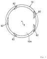
- the crop surface 10a of the piston 10 is a spherical concave surface, so formed in order to avoid interference with the valve bodies 29, 34 of the foregoing air intake valves 26, 27 and exhaust valves 32; further, recesses 62 are present around the outside perimeter of the same crown surface 10a also to avoid interference. Because the crown surface 10a of the piston 10 is a spherical concave surface, the recesses 62 may be relatively shallow, thereby making the overall crown surface 10a comparatively smoother.
- spark plugs 63 are attached to the foregoing cylinder head 7, and the discharge areas 64 of each plug 63 are positioned at the approximate centre of the foregoing combustion chamber 7 with respect to the axis 3 of the foregoing cylinder 2, at the edge of the foregoing combustion chamber 11.
- the inside of the foregoing air intake pipe 14 connects with the foregoing air intake passage 13 to become an air intake passage 66, and there is a butterfly type air intake control valve 67 mounted therein that adjusts the aperture of the air intake passage 66.
- Actuator 68 is a servo motor or other means used to rotate this air intake control valve 67.
- An engine control unit 70 provides the electronic control for the foregoing engine 1.
- the foregoing spark plugs 63 and the actuator 68 are electrically connected with this engine control unit 70.
- variable valve timing device is electrically connected with the foregoing engine control unit 70, which can advance or delay the opening and closing valve timing for the foregoing air intake valves 26, 27 based upon the extent of knocking.
- the above mentioned air intake control valve 67 along with the variable valve timing device, controls the tumbling flow of the foregoing air/fuel mixture 71, and may additionally increase the compression ratio.
- the foregoing air intake control valve 67 can be set in the fully open position as shown by the solid lines in Figures 1 and 2, in the fully closed position as shown by the double-dot broken lines in Figures 1 and 2, or in the half-open position as shown by the single dot broken line in Figure 1.
- the engine performance is improved by these means.
- the exhaust openings 24 are fewer than the air intake openings 18, 19, hence there are also fewer exhaust valves 32 to open and close the foregoing exhaust openings 24 than there are air intake valves 26, 27 to open and close the foregoing air intake openings 18, 19.
- the third intersecting angle ⁇ 3 is increased and the foregoing exhaust valves 32 are moved farther away from the axis 3 of the cylinder 2, amounting to a step which, while taking away some of the latitude in the positioning of these exhaust valves 32, on the other hand improves the latitude in the positioning the foregoing air intake valves 26, 27, which are more numerous.
- the first length L1 is defined as the length from the axis 3 of the cylinder 2 to the axis 45 of the air intake camshaft 43
- the second length L2 will be the length from the axis 3 of the same cylinder 2 to the center of the bolt 6 on the side of the air intake openings 18, 19
- the third length L3 will be the length from the axis 3 of the same cylinder 2 to the center of the bolt 6 on the side of the exhaust openings 24, and the fourth length will be the length from the axis 3 of the same cylinder 2 to the axis 46 of the exhaust camshaft 44, and then the first length L1 ⁇ the second length L2 ⁇ third length L3 ⁇ fourth length L4.
- the bolts 6 on the air intake opening 18, 19 side can be moved farther away from the more numerous air intake valves 26, 27 away from the axis 3 of the cylinder 2, thereby assuring sufficient space separating the various parts.
- bearings 48 are located between left and right adjacent lifters 60, 61.
- the above design allows the space between the left and right adjacent lifters 60, 61 to be effectively utilized for the positioning of the bearings 48 that axially support the air intake camshaft 43 and the exhaust camshaft 44.
- an arc-shaped bend moves them toward the outside and away from the foregoing center branch passage 15.
- the centers of the foregoing side branch passages 16 on their downstream ends are approximately in line with the axes 74 of the air intake valves 27, and further, the downstream ends of the foregoing side branch passages 16 are shaped so that they are directed toward the axis 3 of the cylinder bore 4, through the air intake openings 19.
- the axes 73, 74 of the left and right air intake valves 26, 27 are tilted so that they converge in the downward direction.
- the side air intake valves 27 are tilted with respect to the axis 3 of the cylinder 2, firstly, in order that the top surface of each of the lifters 60 of the foregoing air intake valves 27 make linear contact with the outside circumferential surface of the cam beak 50, the outside circumferential surface of these cam beaks 50 is tapered in the axial direction.
- the lifters 60 for the air intake valves 26, 27 are the same size and shape to provide interchangeability.
- the dimensions from the top end of the side air intake valves 27 to the axis 45 of the air intake camshaft 43 are larger than the corresponding dimensions from the top end of the center air intake valve 26 to the axis 45 of the air intake camshaft 43.
- the diameters of the bases 50a of the cam beaks 50 on the camshaft 43 that correspond to the side air intake valves 27 are greater than the diameters of the bases 50a of the cam beak 50 on the air intake camshaft 43 that correspond to the foregoing center air intake valve 26 (shown by the solid line in Figure 1).
- the dimension a from the mating surface of the foregoing cylinder unit 5 and the cylinder head 7 to the bottom end of the valve body 29 of the air intake valve 26 when closing the centre air intake valve opening 18 is greater than the dimension b from the same mating surface to the bottom ends of the valve bodies 34 of each of the exhaust valves when closing the exhaust openings 24.
- the fuel injection valve used as a fuel supply has been mounted on the cylinder head 7, but the fuel could equally well be provided further downstream of the foregoing air intake control valves 67 in the combustion chamber 11, or it could be injected directly into the air intake passage 13.
- three or more air intake openings are arrayed left and right on one side, in the fore-aft direction, of the cylinder bore in the cylinder head, while on the other side, fewer exhaust openings are arrayed left and right.
- this invention increases the third intersecting angle as described above and shifts the foregoing exhaust valves farther away from the axis of the cylinder, thereby decreasing the latitude in positioning the exhaust valves, but on the other hand providing improved latitude in the location of the more numerous air intake valves.
- the foregoing air intake valves and the exhaust valves can respectively be set closer to each other, providing an optimal placement for the air intake valves and exhaust valves to facilitate their inspection and maintenance.
- the air intake openings which are opened and closed by the air intake valves are consequently shifted fore and aft with respect to each other, thereby enabling them to be closer together in the left-right direction than would be possible if they were simply laid out linearly in the left-right direction.
- the first length is defined as the length from the cylindrical axis to the axis of the air intake cam shaft
- the second length as the length from the same cylindrical axis to the bolt holes on the air intake opening side
- the third length as the length from the same cylindrical axis to the bolt holes on the exhaust opening side
- the fourth length as the length from the same cylindrical axis to the axis of the exhaust camshaft
- the bearings for axially supporting the air intake camshaft and the exhaust camshaft inside the cam housing may also be placed between the left and right adjacent lifters.
- the axes of the left and right air intake valves may be tilted so that they converge in the downward direction.
Landscapes
- Engineering & Computer Science (AREA)
- Mechanical Engineering (AREA)
- General Engineering & Computer Science (AREA)
- Chemical & Material Sciences (AREA)
- Combustion & Propulsion (AREA)
- Valve-Gear Or Valve Arrangements (AREA)
Applications Claiming Priority (3)
| Application Number | Priority Date | Filing Date | Title |
|---|---|---|---|
| JP284166/94 | 1994-10-24 | ||
| JP6284166A JPH08121118A (ja) | 1994-10-24 | 1994-10-24 | 4サイクルエンジン |
| JP28416694 | 1994-10-24 |
Publications (3)
| Publication Number | Publication Date |
|---|---|
| EP0713958A2 true EP0713958A2 (fr) | 1996-05-29 |
| EP0713958A3 EP0713958A3 (fr) | 1997-04-16 |
| EP0713958B1 EP0713958B1 (fr) | 2002-04-03 |
Family
ID=17675042
Family Applications (1)
| Application Number | Title | Priority Date | Filing Date |
|---|---|---|---|
| EP95116746A Expired - Lifetime EP0713958B1 (fr) | 1994-10-24 | 1995-10-24 | Moteur à combustion interne |
Country Status (3)
| Country | Link |
|---|---|
| EP (1) | EP0713958B1 (fr) |
| JP (1) | JPH08121118A (fr) |
| DE (1) | DE69526179T2 (fr) |
Cited By (2)
| Publication number | Priority date | Publication date | Assignee | Title |
|---|---|---|---|---|
| WO1997039222A1 (fr) * | 1996-04-16 | 1997-10-23 | Frederick William Roberts | Systeme de reglage des soupapes |
| AU734474B2 (en) * | 1996-04-16 | 2001-06-14 | Frederick William Roberts | Valve timing system |
Families Citing this family (1)
| Publication number | Priority date | Publication date | Assignee | Title |
|---|---|---|---|---|
| JP2013144941A (ja) * | 2012-01-13 | 2013-07-25 | Suzuki Motor Corp | 内燃機関の動弁装置 |
Family Cites Families (3)
| Publication number | Priority date | Publication date | Assignee | Title |
|---|---|---|---|---|
| DE3838305A1 (de) * | 1988-11-11 | 1990-05-17 | Audi Ag | Zylinderkopf einer brennkraftmaschine |
| JP2766292B2 (ja) * | 1989-03-10 | 1998-06-18 | ヤマハ発動機株式会社 | エンジンの動弁装置 |
| EP0611883B1 (fr) * | 1993-02-19 | 1998-07-08 | Yamaha Hatsudoki Kabushiki Kaisha | Moteur à combustion interne |
-
1994
- 1994-10-24 JP JP6284166A patent/JPH08121118A/ja active Pending
-
1995
- 1995-10-24 DE DE69526179T patent/DE69526179T2/de not_active Expired - Fee Related
- 1995-10-24 EP EP95116746A patent/EP0713958B1/fr not_active Expired - Lifetime
Non-Patent Citations (1)
| Title |
|---|
| None |
Cited By (3)
| Publication number | Priority date | Publication date | Assignee | Title |
|---|---|---|---|---|
| WO1997039222A1 (fr) * | 1996-04-16 | 1997-10-23 | Frederick William Roberts | Systeme de reglage des soupapes |
| AU734474B2 (en) * | 1996-04-16 | 2001-06-14 | Frederick William Roberts | Valve timing system |
| US6386159B1 (en) | 1996-04-16 | 2002-05-14 | Frederick William Roberts | Valve timing system |
Also Published As
| Publication number | Publication date |
|---|---|
| DE69526179T2 (de) | 2002-08-22 |
| EP0713958B1 (fr) | 2002-04-03 |
| EP0713958A3 (fr) | 1997-04-16 |
| JPH08121118A (ja) | 1996-05-14 |
| DE69526179D1 (de) | 2002-05-08 |
Similar Documents
| Publication | Publication Date | Title |
|---|---|---|
| US6443110B2 (en) | Rotary valve head system for multi-cylinder internal combustion engines | |
| US4527518A (en) | Internal combustion engine having single overhead camshaft | |
| SK283125B6 (sk) | Sústava rotačných guľových ventilov na použitie v motore s vnútorným spaľovaním | |
| JPH06317112A (ja) | 内燃機関用シリンダヘッド | |
| JP4454201B2 (ja) | バルブ制御を有する内燃機関 | |
| EP1243780A2 (fr) | Moteur à combustion interne | |
| US20040237926A1 (en) | Semi-rotating valve assembly for use with an internal combustion engine | |
| JP2766292B2 (ja) | エンジンの動弁装置 | |
| US5095870A (en) | Rotary valve four-cycle engine | |
| JPH07208177A (ja) | 筒内燃料噴射式の多気筒エンジン | |
| US4981118A (en) | Poppet valve for internal combustion engine | |
| US4762099A (en) | Valve actuating device of four-cycle internal combustion engine | |
| EP0713958B1 (fr) | Moteur à combustion interne | |
| US5119776A (en) | Compact bearing cap for overhead camshaft | |
| US4615309A (en) | Valve actuating mechanism for internal combustion engine | |
| US6189503B1 (en) | Porting arrangement for direct injected engine | |
| EP0747583A1 (fr) | Moteur à combustion interne avec préchambre de combustion à vortex | |
| KR20000005309A (ko) | 2행정 내연 엔진용 공기 및 배기 가스 조절 장치 | |
| US4864981A (en) | Overhead valve type engine | |
| US1286435A (en) | Internal-combustion engine. | |
| EP0971116B1 (fr) | Moteur à combustion interne | |
| EP1243760A2 (fr) | Moteur à combustion interne | |
| EP0808418B1 (fr) | Culasse dans un moteur a combustion interne | |
| US6209512B1 (en) | Small-dimension two or four stroke vehicle engine with stratified feed | |
| JP3767716B2 (ja) | 過給ポンプ付き火花点火式4サイクル内燃機関 |
Legal Events
| Date | Code | Title | Description |
|---|---|---|---|
| PUAI | Public reference made under article 153(3) epc to a published international application that has entered the european phase |
Free format text: ORIGINAL CODE: 0009012 |
|
| AK | Designated contracting states |
Kind code of ref document: A2 Designated state(s): DE FR GB IT |
|
| PUAL | Search report despatched |
Free format text: ORIGINAL CODE: 0009013 |
|
| AK | Designated contracting states |
Kind code of ref document: A3 Designated state(s): DE FR GB IT |
|
| 17P | Request for examination filed |
Effective date: 19971009 |
|
| 17Q | First examination report despatched |
Effective date: 19991117 |
|
| GRAG | Despatch of communication of intention to grant |
Free format text: ORIGINAL CODE: EPIDOS AGRA |
|
| GRAG | Despatch of communication of intention to grant |
Free format text: ORIGINAL CODE: EPIDOS AGRA |
|
| GRAG | Despatch of communication of intention to grant |
Free format text: ORIGINAL CODE: EPIDOS AGRA |
|
| GRAH | Despatch of communication of intention to grant a patent |
Free format text: ORIGINAL CODE: EPIDOS IGRA |
|
| REG | Reference to a national code |
Ref country code: GB Ref legal event code: IF02 |
|
| GRAH | Despatch of communication of intention to grant a patent |
Free format text: ORIGINAL CODE: EPIDOS IGRA |
|
| GRAA | (expected) grant |
Free format text: ORIGINAL CODE: 0009210 |
|
| AK | Designated contracting states |
Kind code of ref document: B1 Designated state(s): DE FR GB IT |
|
| REF | Corresponds to: |
Ref document number: 69526179 Country of ref document: DE Date of ref document: 20020508 |
|
| ET | Fr: translation filed | ||
| PLBE | No opposition filed within time limit |
Free format text: ORIGINAL CODE: 0009261 |
|
| STAA | Information on the status of an ep patent application or granted ep patent |
Free format text: STATUS: NO OPPOSITION FILED WITHIN TIME LIMIT |
|
| 26N | No opposition filed |
Effective date: 20030106 |
|
| PGFP | Annual fee paid to national office [announced via postgrant information from national office to epo] |
Ref country code: GB Payment date: 20061018 Year of fee payment: 12 |
|
| PGFP | Annual fee paid to national office [announced via postgrant information from national office to epo] |
Ref country code: DE Payment date: 20061019 Year of fee payment: 12 |
|
| PGFP | Annual fee paid to national office [announced via postgrant information from national office to epo] |
Ref country code: IT Payment date: 20061031 Year of fee payment: 12 |
|
| GBPC | Gb: european patent ceased through non-payment of renewal fee |
Effective date: 20071024 |
|
| PG25 | Lapsed in a contracting state [announced via postgrant information from national office to epo] |
Ref country code: DE Free format text: LAPSE BECAUSE OF NON-PAYMENT OF DUE FEES Effective date: 20080501 |
|
| REG | Reference to a national code |
Ref country code: FR Ref legal event code: ST Effective date: 20080630 |
|
| PGFP | Annual fee paid to national office [announced via postgrant information from national office to epo] |
Ref country code: FR Payment date: 20061010 Year of fee payment: 12 |
|
| PG25 | Lapsed in a contracting state [announced via postgrant information from national office to epo] |
Ref country code: GB Free format text: LAPSE BECAUSE OF NON-PAYMENT OF DUE FEES Effective date: 20071024 |
|
| PG25 | Lapsed in a contracting state [announced via postgrant information from national office to epo] |
Ref country code: FR Free format text: LAPSE BECAUSE OF NON-PAYMENT OF DUE FEES Effective date: 20071031 |
|
| PG25 | Lapsed in a contracting state [announced via postgrant information from national office to epo] |
Ref country code: IT Free format text: LAPSE BECAUSE OF NON-PAYMENT OF DUE FEES Effective date: 20071024 |