EP0714014B1 - Wasserwaage - Google Patents
Wasserwaage Download PDFInfo
- Publication number
- EP0714014B1 EP0714014B1 EP95117501A EP95117501A EP0714014B1 EP 0714014 B1 EP0714014 B1 EP 0714014B1 EP 95117501 A EP95117501 A EP 95117501A EP 95117501 A EP95117501 A EP 95117501A EP 0714014 B1 EP0714014 B1 EP 0714014B1
- Authority
- EP
- European Patent Office
- Prior art keywords
- holder
- level
- spirit level
- hollow profile
- feature
- Prior art date
- Legal status (The legal status is an assumption and is not a legal conclusion. Google has not performed a legal analysis and makes no representation as to the accuracy of the status listed.)
- Expired - Lifetime
Links
Images


Classifications
-
- G—PHYSICS
- G01—MEASURING; TESTING
- G01C—MEASURING DISTANCES, LEVELS OR BEARINGS; SURVEYING; NAVIGATION; GYROSCOPIC INSTRUMENTS; PHOTOGRAMMETRY OR VIDEOGRAMMETRY
- G01C9/00—Measuring inclination, e.g. by clinometers, by levels
- G01C9/18—Measuring inclination, e.g. by clinometers, by levels by using liquids
- G01C9/24—Measuring inclination, e.g. by clinometers, by levels by using liquids in closed containers partially filled with liquid so as to leave a gas bubble
- G01C9/26—Details
- G01C9/28—Mountings
Definitions
- the invention relates to spirit levels with a closed, Tolerant hollow profile according to the preamble of Claim 1.
- Spirit levels are used annually in large numbers worldwide sold. They essentially consist of one elongated parallelepiped hollow profile, mostly made of Aluminum, the open ends of which are shock-absorbing end caps can be closed. Usually two or more viewing windows are provided, each with a view of a horizontal or Release the vertical dragonfly. The dragonflies are to the measuring sole the spirit level is precisely adjusted. This adjustment should also for rough operation on construction sites etc. for one if possible remain for a long time. For this reason, the Construction of the corresponding holding devices and their Assembly devoted a lot of time and attention.
- the crystal-clear dragonfly body is made with the help of a Dragonfly holder made of plastic fastened in the hollow profile.
- the attachment is carried out with the help of a shrinkage-free curing adhesive.
- This Attachment is for both horizontal and for Suitable for vertical dragonflies and has grown over the past few years Well proven for decades. However, it is time consuming and expensive. The spirit levels must be activated while the Glue are secured by special precautions so that the adjusted dragonfly does not move.
- a combined screw and adhesive assembly of the Dragonfly holder of a horizontal dragonfly shows the DE-PS 23 51 194.
- a clamp for the dragonfly holder for DE-C-35 32 123 shows horizontal vials in the hollow profile.
- the outer surfaces of the dragonfly holder are for this purpose provided with knobs, ribs or the like, the one Excess in relation to the internal dimensions of the hollow profile have. This will make the vial holder in the hollow profile jammed.
- the present invention has for its object a To specify a spirit level of the type mentioned, which the fast, automated installation and adjustment of the Dragonflies, d. H. both the horizontal dragonflies and the Vertical dragonflies, as well as a permanent, secure fit of dragonflies.
- the invention is based on the fact that there is always at least one Pillar that holds the dragonfly holder in the extended position in the Wedge hollow profile, and that the straight column is not on Bending, but is subject to buckling. This is ensured by a correspondingly flat one Wedge shape of the top of the column block.
- the kink resistance is much higher than the bending strength. Due to the high The dragonfly fixation can withstand high forces take up. The lack of deflection reduces the holding force this pillar even after a long time.
- the higher, more bent pillars push the The level of the dragonfly holder during assembly and Adjustment firmly against the hollow profile and thus ensure one clearly defined, stable location, what condition for a safe and precise adjustment of the dragonfly. At correct dimensioning, the forces remain so low that the hollow profile is not braced.
- the columns are not circular or square, rather than slats with rectangular Cross section formed.
- At least two parallel column blocks are provided, the are mutually spaced.
- the columns of one column block preferably stand up Gap to the pillars of the other pillar block. This simplifies injection molding production.
- the support sole or the are advantageously supported Columns on the narrow sides and / or the broad sides of the Hollow profile, preferably on the stiff Profile sheets.
- Assembly aids, for example in the form of wedge-shaped trained guide slats, allow a quick Assembly and prevent damage to the columns when Push the level holder into the hollow profile.
- a Dragonfly intake provided. This sits between Dragonfly holder and dragonfly body and has the purpose of a immediate and immovable fixation of the adjusted dragonfly to enable by means of ultrasonic welding.
- a can between the level holder and hollow profile Potting compound or an adhesive can be injected. Since the Dragonfly holder already through the columns and the Dragonfly image with a dragonfly Ultrasonic welding are fixed for that No special hardening of casting compound or adhesive Precautions are taken to prevent the dragonflies from moving become.
- the dragonfly holder consists of two parts that go through each other Have the viewing window inserted into the hollow profile.
- Each Part has at least one column block and one Overlay sole. Both parts are in their hollow profile Movable end position. This is particularly suitable for the assembly of horizontal vials in long Spirit level hollow profiles and prevents the insertion of the Dragonfly holder from the open face of the hollow profile forth.
- both parts of the level holder are identical.
- Each part preferably has an integrally molded part Spreading slope, suitable for a spreading tool with a Spreading element, e.g. B. an expanding wedge.
- a Spreading element e.g. B. an expanding wedge.
- This expansion wedge can be part of the Dragonfly body or the dragonfly recording itself.
- the level holder 20 is a Plastic injection molded part with a body 21 circular opening that a seat 23 for one Dragonfly body 2 with dragonfly 1 forms.
- the level holder 20 is a Plastic injection molded part with a body 21 circular opening that a seat 23 for one Dragonfly body 2 with dragonfly 1 forms.
- This have a variety of transverse to the insertion direction E.
- oriented slats 43, 44, 45 with rectangular Cross section and graded height so that the top in Insertion direction E increases slightly wedge-shaped.
- the assembly aid 46 the protects the slats 43, 44, 45 during assembly.
- the level holder 20 stands up with its support soles 22 a narrow side 12 of the hollow profile 11.
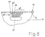
- the slat blocks 40, 41 clamp the level holder 20 against the opposite narrow side 12 of the hollow profile 11. Because the slats 43, 44, 45 each hollow profile in question 11 can adapt, this leads to an extremely stable and permanent fixation, even when using hollow profiles 11 with large tolerances and small wall thickness.
- the Slats 43, 44, 45 are graded so that they at least the entire tolerance range of the inner height of the hollow profile 11 cover.
- the fatigue strength of these long slats 45 is, however unsatisfactory, because the spring action over time Stress relief in the plastic decreases significantly.
- the secure, permanent hold of the dragonfly holder 20 is thereby ensuring that 40, 41 each per block of slats at least one lamella 44 is stretched in the hollow profile 11.
- This stretched lamella 44 is kinked stressed and can therefore permanently large forces record which when adjusting the level 1 and arise in particular when using the spirit level 10 can.
- the kink resistance is much higher than that Flexural strength.
- the lamellar blocks the dragonfly holder 20 also between the broad sides 15 of the hollow profile 11 can brace.
- FIG. 1 and 2 show the edge of the Viewing window 13 in the hollow profile 11, the edge of the Dragonfly body 2 and the visible parts of the Dragonfly holder 20 and the dragonfly holder 60 with the help a cover 50 optically covered.
- This lid 50 can with level holder 20, level holder 60 and / or Dragonfly body 2 locked, jammed, glued and / or are welded, in particular by means of ultrasound.
- Level holder 20 and / or level holder 60 toothing 29 be molded.
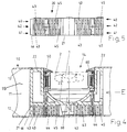
- FIGS. 4 and 5 show as a second embodiment a level holder 20 for a horizontal level.
- the Dragonfly holder 20 has compared to its two Support soles 22 two slat blocks 40, 41 each the slats of a slat block 40, 41 to gap the slats of the other slat block 40, 41, which the injection molding manufacturing easier.
- the vial holder 20 is also in this case by the inserted open end of the hollow profile 11 until it is correctly positioned to the viewing window 14. To the dragonfly To be able to adjust 1, the level holder 20 has one circular seat 23 for the corresponding trained bottom of the dragonfly receptacle 60.
- Suitable glue points are the spaces between the lamella blocks 40, 41, the spaces between the lamella blocks 40, 41 and the hollow profile 11, the spaces between the dragonfly holder 20 and hollow profile 11, as well as the gap between the Dragonfly holder 20, the dragonfly holder 60, the Dragonfly body 2 and cover 50.
- the Dragonfly holder 30 consists of two parts 31, 32 with each a support sole 22 and at least one each Lamella block 40.
- the two vial holder parts 31, 32 are preferably identical; in any case they are like that trained that they through the window 14 in the hollow profile 11 can be used simultaneously or in succession can.
- the two vial holder parts 31, 32 After assembly, the two vial holder parts 31, 32 by welding or gluing together and if necessary, be connected to the dragonfly receptacle 60.
- Two-part dragonfly holders 30 allow a special easy installation of horizontal vials in hollow profiles 11 of very long spirit levels 10.
Landscapes
- Physics & Mathematics (AREA)
- Engineering & Computer Science (AREA)
- General Physics & Mathematics (AREA)
- Radar, Positioning & Navigation (AREA)
- Remote Sensing (AREA)
- Toys (AREA)
- Control Of Motors That Do Not Use Commutators (AREA)
- Details Of Rigid Or Semi-Rigid Containers (AREA)
- Containers Having Bodies Formed In One Piece (AREA)
- Reinforcement Elements For Buildings (AREA)
Description
- Fig. 1
- ausschnittsweise einen Längsschnitt durch eine Wasserwaage mit teilmontierter Vertikal-Libelle,
- Fig. 2
- einen Querschnitt durch die Wasserwaage der Fig. 1 entlang der Linie II-II,
- Fig. 3
- eine Draufsicht auf die Oberseite des Libellenhalters der Fig. 1 und 2,
- Fig. 4
- ausschnittsweise einen Längsschnitt durch eine Wasserwaage mit montierter Horizontal-Libelle,
- Fig. 5
- eine Draufsicht auf die Oberseite des Libellenhalters für die Montage einer Horizontal-Libelle gemäß Fig. 4,
- Fig. 6
- einen zweiteiligen Libellenhalter für die Montage einer Horizontal-Libelle vor dem Montieren in einer Wasserwaage,
- Fig. 7
- ausschnittsweise einen Längsschnitt durch die Wasserwaage der Fig. 6 nach Montage des zweiteiligen Libellenhalters und
- Fig. 8
- ausschnittsweise einen Lamellenblock nach der Montage im Hohlprofil.
Claims (14)
- Wasserwaage (10) mit einem geschlossenen, toleranzbehafteten Hohlprofil (11), welches ein den Blick auf eine Libelle (1) freigebendes Fenster (13) besitzt, und einem Libellenhalter (20, 30) aus Kunststoff zum Einklemmen in das Hohlprofil (11), umfassendgekennzeichnet durch die Merkmale:einen Sitz (23) für die justierbare Aufnahme des Libellenkörpers (2),eine Fixiereinrichtung zur dauerhaften Fixierung des justierten Libellenkörpers (2)und eine Klemmeinrichtung zur dauerhaften Klemmbefestigung des Libellenhalters (20) im Hohlprofil (11),der Libellenhalter (20, 30) besitztmindestens eine Auflagesohle (22) undder Auflagesohle (22) gegenüber wenigstens einen Säulenblock (40, 41) mit einer Vielzahl elastischer, biegesteifer Säulen (43, 44, 45),die Säulen (43 ... 45) stehen quer zur Einschubrichtung (E) und sind in der Höhe derart abgestuft, daß die Oberseite (47) des Säulenblocks (40, 41) in Einschubrichtung (E) leicht keilförmig ansteigt,wenigstens eine auf Knickung beanspruchte Säule (44) verspannt den Libellenhalter (20) im Hohlprofil (11).
- Wasserwaage nach Anspruch 1, gekennzeichnet durch das Merkmal:die Säulen (43, 44, 45) sind als Lamellen mit rechteckigem Querschnitt ausgebildet.
- Wasserwaage nach Anspruch 1 oder 2, gekennzeichnet durch das Merkmal:es sind zwei parallele Säulenblöcke (40, 41) vorgesehen.
- Wasserwaage nach Anspruch 3, gekennzeichnet durch das Merkmal:die Säulen des einen Säulenblocks (40) stehen auf Lücke zu den Säulen des anderen Säulenblocks (41).
- Wasserwaage nach einem der Ansprüche 1 bis 4, gekennzeichnet durch das Merkmal:die Auflagesohle (22) bzw. die Säulen (44, 45) stützen sich an den Schmalseiten (12) und/oder den Breitseiten (15) des Hohlprofils (11) ab, bevorzugt an den steifen Profilecken.
- Wasserwaage nach einem der Ansprüche 1 bis 5, gekennzeichnet durch das Merkmal:am Libellenhalter (20, 30) sind in Einschubrichtung (E) vorne Montagehilfen (46) angeformt,die das Einführen in das Hohlprofil (11) erleichternund eine Beschädigung der Lamellen (43 ... 45) verhindern.
- Wasserwaage nach einem der Ansprüche 1 bis 6, gekennzeichnet durch das Merkmal:zwischen Libellenhalter (20, 30) und Libellenkörper (2) ist eine Libellenaufnahme (60) vorgesehen,Libellenhalter (20, 30) oder Libellenaufnahme (60) besitzen an der Schweißstelle eine feine Verzahnung (29).
- Wasserwaage nach einem der Ansprüche 1 bis 7, gekennzeichnet durch das Merkmal:die Libellenaufnahme (60) und/oder ein Deckel (50) fixieren den Libellenhalter (20) formschlüssig im Sichtfenster (13, 14).
- Wasserwaage nach einem der Ansprüche 1 bis 8, gekennzeichnet durch das Merkmal:die Lamellen eines Lamellenblocks (40, 41) sind zu einem Paket verschweißt.
- Wasserwaage nach einem der Ansprüche 1 bis 9, gekennzeichnet durch das Merkmal:eine Vergußmasse füllt alle Zwischenräume zwischen den Säulen (43, 44, 45) aus und befestigt den Libellenhalter (20, 30) zusätzlich im Hohlprofil (11).
- Wasserwaage nach einem der Ansprüche 1 bis 10, gekennzeichnet durch die Merkmale:der Libellenhalter (30) besteht aus zwei Teilen (31, 32),beide Teile (31, 32) lassen sich durch das Sichtfenster (14) in das Hohlprofil (11) einsetzen,jedes Teil (31, 32) besitzt mindestens eine Auflagesohle (22) und wenigstens einen Säulenblock (40),beide Teile (31, 32) sind im Hohlprofil (11) in ihre Endpositionen verschiebbar.
- Wasserwaage nach Anspruch 11, gekennzeichnet durch das Merkmal:beide Teile (31, 32) sind identisch.
- Wasserwaage nach Anspruch 11 oder 12, gekennzeichnet durch das Merkmal:jedes Teil (31, 32) besitzt eine angeformte Spreizschräge (33),passend zu einem Spreizwerkzeug (34) mit einem Spreizelement, z. B. einem Spreizkeil (35).
- Wasserwaage nach Anspruch 13, gekennzeichnet durch das Merkmal:der Spreizkeil (35) ist Teil des Libellenkörpers (2) oder der Libellenaufnahme (60).
Applications Claiming Priority (2)
| Application Number | Priority Date | Filing Date | Title |
|---|---|---|---|
| DE4441657 | 1994-11-23 | ||
| DE4441657A DE4441657A1 (de) | 1994-11-23 | 1994-11-23 | Wasserwaage |
Publications (2)
| Publication Number | Publication Date |
|---|---|
| EP0714014A1 EP0714014A1 (de) | 1996-05-29 |
| EP0714014B1 true EP0714014B1 (de) | 1999-01-27 |
Family
ID=6533928
Family Applications (1)
| Application Number | Title | Priority Date | Filing Date |
|---|---|---|---|
| EP95117501A Expired - Lifetime EP0714014B1 (de) | 1994-11-23 | 1995-11-07 | Wasserwaage |
Country Status (5)
| Country | Link |
|---|---|
| EP (1) | EP0714014B1 (de) |
| AT (1) | ATE176315T1 (de) |
| DE (2) | DE4441657A1 (de) |
| DK (1) | DK0714014T3 (de) |
| ES (1) | ES2129732T3 (de) |
Families Citing this family (1)
| Publication number | Priority date | Publication date | Assignee | Title |
|---|---|---|---|---|
| US7832112B2 (en) | 2008-11-10 | 2010-11-16 | Empire Level Mfg. Co. | Vial-mounting structure |
Family Cites Families (6)
| Publication number | Priority date | Publication date | Assignee | Title |
|---|---|---|---|---|
| DE2254456C3 (de) | 1972-11-07 | 1975-06-26 | Messwerkzeug Kg, Gustav Ullrich, 6747 Annweiler | Wasserwaage mit einem Wasserwaagenkörper aus einem Hohlprofil |
| DE2351194C2 (de) | 1973-10-11 | 1975-10-30 | Messwerkzeug Kg, Gustav Ullrich, 6747 Annweiler | Wasserwaage |
| DE3127399A1 (de) * | 1981-07-10 | 1983-01-27 | Stabila-Messgeräte Gustav Ullrich GmbH & Co KG, 6747 Annweiler | Wasserwaage |
| DE3532123A1 (de) | 1985-09-10 | 1987-03-12 | Keller Bayer Mass Ind | Wasserwaage |
| DE3606774A1 (de) | 1986-03-01 | 1987-09-03 | Keller Bayer Mass Ind | Vorrichtung zum befestigen der libelle einer wasserwaage |
| DE3707425A1 (de) * | 1987-03-07 | 1988-09-15 | Keller Bayer Mass Ind | Wasserwaage |
-
1994
- 1994-11-23 DE DE4441657A patent/DE4441657A1/de not_active Withdrawn
-
1995
- 1995-11-07 DE DE59504973T patent/DE59504973D1/de not_active Expired - Lifetime
- 1995-11-07 ES ES95117501T patent/ES2129732T3/es not_active Expired - Lifetime
- 1995-11-07 DK DK95117501T patent/DK0714014T3/da active
- 1995-11-07 EP EP95117501A patent/EP0714014B1/de not_active Expired - Lifetime
- 1995-11-07 AT AT95117501T patent/ATE176315T1/de active
Also Published As
| Publication number | Publication date |
|---|---|
| EP0714014A1 (de) | 1996-05-29 |
| DE59504973D1 (de) | 1999-03-11 |
| ATE176315T1 (de) | 1999-02-15 |
| DE4441657A1 (de) | 1996-05-30 |
| ES2129732T3 (es) | 1999-06-16 |
| DK0714014T3 (da) | 1999-09-13 |
Similar Documents
| Publication | Publication Date | Title |
|---|---|---|
| DE2502619C3 (de) | Bausatz zum Aufbau eines zur Aufnahme von Instrumenten, insbesondere Laborinstrumenten, bestimmten Gestells | |
| EP0683287B1 (de) | Profilschiene zur Befestigung flächiger Gegenstände | |
| DE3530694C2 (de) | ||
| DE202007015604U1 (de) | Verbindungsbeschlag für Leichtbauplatten | |
| DE2829715A1 (de) | Werkzeug- oder messmaschine | |
| DE3323624C2 (de) | ||
| DE4432607A1 (de) | Kraftmeßvorrichtung | |
| DE2636434B2 (de) | Rahmeneckverbindung | |
| EP0315936A1 (de) | Klotzteil zum Festsetzen von Glasscheiben od. dgl. | |
| DE2923903C2 (de) | ||
| AT516721B1 (de) | Geländer und Verfahren zur Herstellung eines Geländers | |
| DE2735825C2 (de) | ||
| DE4441657A1 (de) | Wasserwaage | |
| CH700182B1 (de) | Rohrhalterung. | |
| DE3203804C2 (de) | ||
| DE19505141A1 (de) | Verfahren zur Verbindung zweier parallel aufeinanderliegender Flachtafeln und Vorrichtung zur Durchführung des Verfahrens | |
| WO1991012360A1 (de) | Webschaft mit lösbaren eckverbindungen | |
| AT410978B (de) | Wasserwaage mit einem hohlprofil | |
| DE102005058386A1 (de) | Pfosten-Riegel-Verbindung | |
| DE1759642B2 (de) | Mehrfach verstellbares scharnier | |
| DE2416615C3 (de) | Eckverbindung für Abstandsprofile für Mehrscheibenisolierglas | |
| DE3236578A1 (de) | Rahmenspanngeraet | |
| EP3742003A1 (de) | Haltevorrichtung für ein flächenelement | |
| DE9011138U1 (de) | Montageelement | |
| DE20012299U1 (de) | Führungsgestell |
Legal Events
| Date | Code | Title | Description |
|---|---|---|---|
| PUAI | Public reference made under article 153(3) epc to a published international application that has entered the european phase |
Free format text: ORIGINAL CODE: 0009012 |
|
| AK | Designated contracting states |
Kind code of ref document: A1 Designated state(s): AT BE CH DE DK ES FR GB IT LI NL SE |
|
| 17P | Request for examination filed |
Effective date: 19960510 |
|
| GRAG | Despatch of communication of intention to grant |
Free format text: ORIGINAL CODE: EPIDOS AGRA |
|
| GRAG | Despatch of communication of intention to grant |
Free format text: ORIGINAL CODE: EPIDOS AGRA |
|
| GRAH | Despatch of communication of intention to grant a patent |
Free format text: ORIGINAL CODE: EPIDOS IGRA |
|
| 17Q | First examination report despatched |
Effective date: 19980414 |
|
| GRAH | Despatch of communication of intention to grant a patent |
Free format text: ORIGINAL CODE: EPIDOS IGRA |
|
| GRAA | (expected) grant |
Free format text: ORIGINAL CODE: 0009210 |
|
| AK | Designated contracting states |
Kind code of ref document: B1 Designated state(s): AT BE CH DE DK ES FR GB IT LI NL SE |
|
| REF | Corresponds to: |
Ref document number: 176315 Country of ref document: AT Date of ref document: 19990215 Kind code of ref document: T |
|
| REG | Reference to a national code |
Ref country code: CH Ref legal event code: EP |
|
| REF | Corresponds to: |
Ref document number: 59504973 Country of ref document: DE Date of ref document: 19990311 |
|
| ITF | It: translation for a ep patent filed | ||
| REG | Reference to a national code |
Ref country code: CH Ref legal event code: NV Representative=s name: PATENTANWAELTE SCHAAD, BALASS, MENZL & PARTNER AG |
|
| ET | Fr: translation filed | ||
| GBT | Gb: translation of ep patent filed (gb section 77(6)(a)/1977) |
Effective date: 19990429 |
|
| REG | Reference to a national code |
Ref country code: ES Ref legal event code: FG2A Ref document number: 2129732 Country of ref document: ES Kind code of ref document: T3 |
|
| REG | Reference to a national code |
Ref country code: DK Ref legal event code: T3 |
|
| PLBE | No opposition filed within time limit |
Free format text: ORIGINAL CODE: 0009261 |
|
| STAA | Information on the status of an ep patent application or granted ep patent |
Free format text: STATUS: NO OPPOSITION FILED WITHIN TIME LIMIT |
|
| 26N | No opposition filed | ||
| REG | Reference to a national code |
Ref country code: GB Ref legal event code: IF02 |
|
| PGFP | Annual fee paid to national office [announced via postgrant information from national office to epo] |
Ref country code: NL Payment date: 20081120 Year of fee payment: 14 Ref country code: DK Payment date: 20081121 Year of fee payment: 14 Ref country code: CH Payment date: 20081124 Year of fee payment: 14 |
|
| PGFP | Annual fee paid to national office [announced via postgrant information from national office to epo] |
Ref country code: ES Payment date: 20081121 Year of fee payment: 14 |
|
| PGFP | Annual fee paid to national office [announced via postgrant information from national office to epo] |
Ref country code: BE Payment date: 20081203 Year of fee payment: 14 Ref country code: IT Payment date: 20081126 Year of fee payment: 14 Ref country code: SE Payment date: 20081124 Year of fee payment: 14 |
|
| PGFP | Annual fee paid to national office [announced via postgrant information from national office to epo] |
Ref country code: FR Payment date: 20081118 Year of fee payment: 14 |
|
| BERE | Be: lapsed |
Owner name: STABILA-MESSGERATE GUSTAV *ULLRICH G.M.B.H. & CO. Effective date: 20091130 |
|
| REG | Reference to a national code |
Ref country code: NL Ref legal event code: V1 Effective date: 20100601 |
|
| EUG | Se: european patent has lapsed | ||
| REG | Reference to a national code |
Ref country code: CH Ref legal event code: PL |
|
| REG | Reference to a national code |
Ref country code: DK Ref legal event code: EBP |
|
| REG | Reference to a national code |
Ref country code: FR Ref legal event code: ST Effective date: 20100730 |
|
| PG25 | Lapsed in a contracting state [announced via postgrant information from national office to epo] |
Ref country code: NL Free format text: LAPSE BECAUSE OF NON-PAYMENT OF DUE FEES Effective date: 20100601 Ref country code: LI Free format text: LAPSE BECAUSE OF NON-PAYMENT OF DUE FEES Effective date: 20091130 Ref country code: FR Free format text: LAPSE BECAUSE OF NON-PAYMENT OF DUE FEES Effective date: 20091130 Ref country code: CH Free format text: LAPSE BECAUSE OF NON-PAYMENT OF DUE FEES Effective date: 20091130 Ref country code: BE Free format text: LAPSE BECAUSE OF NON-PAYMENT OF DUE FEES Effective date: 20091130 |
|
| PG25 | Lapsed in a contracting state [announced via postgrant information from national office to epo] |
Ref country code: DK Free format text: LAPSE BECAUSE OF NON-PAYMENT OF DUE FEES Effective date: 20091130 |
|
| REG | Reference to a national code |
Ref country code: ES Ref legal event code: FD2A Effective date: 20110304 |
|
| PG25 | Lapsed in a contracting state [announced via postgrant information from national office to epo] |
Ref country code: IT Free format text: LAPSE BECAUSE OF NON-PAYMENT OF DUE FEES Effective date: 20091107 |
|
| PG25 | Lapsed in a contracting state [announced via postgrant information from national office to epo] |
Ref country code: SE Free format text: LAPSE BECAUSE OF NON-PAYMENT OF DUE FEES Effective date: 20091108 |
|
| PG25 | Lapsed in a contracting state [announced via postgrant information from national office to epo] |
Ref country code: ES Free format text: LAPSE BECAUSE OF NON-PAYMENT OF DUE FEES Effective date: 20110303 |
|
| PG25 | Lapsed in a contracting state [announced via postgrant information from national office to epo] |
Ref country code: ES Free format text: LAPSE BECAUSE OF NON-PAYMENT OF DUE FEES Effective date: 20091108 |
|
| PGFP | Annual fee paid to national office [announced via postgrant information from national office to epo] |
Ref country code: GB Payment date: 20141120 Year of fee payment: 20 Ref country code: DE Payment date: 20141105 Year of fee payment: 20 |
|
| PGFP | Annual fee paid to national office [announced via postgrant information from national office to epo] |
Ref country code: AT Payment date: 20141119 Year of fee payment: 20 |
|
| REG | Reference to a national code |
Ref country code: DE Ref legal event code: R071 Ref document number: 59504973 Country of ref document: DE |
|
| REG | Reference to a national code |
Ref country code: GB Ref legal event code: PE20 Expiry date: 20151106 |
|
| REG | Reference to a national code |
Ref country code: AT Ref legal event code: MK07 Ref document number: 176315 Country of ref document: AT Kind code of ref document: T Effective date: 20151107 |
|
| PG25 | Lapsed in a contracting state [announced via postgrant information from national office to epo] |
Ref country code: GB Free format text: LAPSE BECAUSE OF EXPIRATION OF PROTECTION Effective date: 20151106 |