EP0714818B1 - Coussin gonflable pour collision latérale - Google Patents
Coussin gonflable pour collision latérale Download PDFInfo
- Publication number
- EP0714818B1 EP0714818B1 EP95118875A EP95118875A EP0714818B1 EP 0714818 B1 EP0714818 B1 EP 0714818B1 EP 95118875 A EP95118875 A EP 95118875A EP 95118875 A EP95118875 A EP 95118875A EP 0714818 B1 EP0714818 B1 EP 0714818B1
- Authority
- EP
- European Patent Office
- Prior art keywords
- gas bag
- ply
- wall
- folded
- section
- Prior art date
- Legal status (The legal status is an assumption and is not a legal conclusion. Google has not performed a legal analysis and makes no representation as to the accuracy of the status listed.)
- Expired - Lifetime
Links
- 238000005192 partition Methods 0.000 claims description 15
- 239000004744 fabric Substances 0.000 claims description 14
- 230000007704 transition Effects 0.000 claims description 7
- 238000004519 manufacturing process Methods 0.000 description 2
- 238000000034 method Methods 0.000 description 2
- 230000001681 protective effect Effects 0.000 description 2
- 230000003292 diminished effect Effects 0.000 description 1
- 230000006641 stabilisation Effects 0.000 description 1
- 238000011105 stabilization Methods 0.000 description 1
Images


Classifications
-
- B—PERFORMING OPERATIONS; TRANSPORTING
- B60—VEHICLES IN GENERAL
- B60R—VEHICLES, VEHICLE FITTINGS, OR VEHICLE PARTS, NOT OTHERWISE PROVIDED FOR
- B60R21/00—Arrangements or fittings on vehicles for protecting or preventing injuries to occupants or pedestrians in case of accidents or other traffic risks
- B60R21/02—Occupant safety arrangements or fittings, e.g. crash pads
- B60R21/16—Inflatable occupant restraints or confinements designed to inflate upon impact or impending impact, e.g. air bags
- B60R21/23—Inflatable members
- B60R21/231—Inflatable members characterised by their shape, construction or spatial configuration
- B60R21/233—Inflatable members characterised by their shape, construction or spatial configuration comprising a plurality of individual compartments; comprising two or more bag-like members, one within the other
-
- B—PERFORMING OPERATIONS; TRANSPORTING
- B60—VEHICLES IN GENERAL
- B60R—VEHICLES, VEHICLE FITTINGS, OR VEHICLE PARTS, NOT OTHERWISE PROVIDED FOR
- B60R21/00—Arrangements or fittings on vehicles for protecting or preventing injuries to occupants or pedestrians in case of accidents or other traffic risks
- B60R21/02—Occupant safety arrangements or fittings, e.g. crash pads
- B60R21/16—Inflatable occupant restraints or confinements designed to inflate upon impact or impending impact, e.g. air bags
- B60R21/23—Inflatable members
- B60R21/231—Inflatable members characterised by their shape, construction or spatial configuration
- B60R21/23138—Inflatable members characterised by their shape, construction or spatial configuration specially adapted for side protection
-
- B—PERFORMING OPERATIONS; TRANSPORTING
- B60—VEHICLES IN GENERAL
- B60R—VEHICLES, VEHICLE FITTINGS, OR VEHICLE PARTS, NOT OTHERWISE PROVIDED FOR
- B60R21/00—Arrangements or fittings on vehicles for protecting or preventing injuries to occupants or pedestrians in case of accidents or other traffic risks
- B60R21/02—Occupant safety arrangements or fittings, e.g. crash pads
- B60R21/16—Inflatable occupant restraints or confinements designed to inflate upon impact or impending impact, e.g. air bags
- B60R21/23—Inflatable members
- B60R21/237—Inflatable members characterised by the way they are folded
-
- B—PERFORMING OPERATIONS; TRANSPORTING
- B60—VEHICLES IN GENERAL
- B60R—VEHICLES, VEHICLE FITTINGS, OR VEHICLE PARTS, NOT OTHERWISE PROVIDED FOR
- B60R21/00—Arrangements or fittings on vehicles for protecting or preventing injuries to occupants or pedestrians in case of accidents or other traffic risks
- B60R2021/0002—Type of accident
- B60R2021/0006—Lateral collision
-
- B—PERFORMING OPERATIONS; TRANSPORTING
- B60—VEHICLES IN GENERAL
- B60R—VEHICLES, VEHICLE FITTINGS, OR VEHICLE PARTS, NOT OTHERWISE PROVIDED FOR
- B60R21/00—Arrangements or fittings on vehicles for protecting or preventing injuries to occupants or pedestrians in case of accidents or other traffic risks
- B60R21/02—Occupant safety arrangements or fittings, e.g. crash pads
- B60R21/16—Inflatable occupant restraints or confinements designed to inflate upon impact or impending impact, e.g. air bags
- B60R21/23—Inflatable members
- B60R21/231—Inflatable members characterised by their shape, construction or spatial configuration
- B60R21/233—Inflatable members characterised by their shape, construction or spatial configuration comprising a plurality of individual compartments; comprising two or more bag-like members, one within the other
- B60R2021/23324—Inner walls crating separate compartments, e.g. communicating with vents
Definitions
- the invention relates to a side impact gas bag for a Vehicle occupant restraint system, with a wall in which an inlet opening is provided for inflating the gas bag and a partition inside the airbag, which divides the interior of the airbag into two adjacent chambers, through a connection opening formed in the partition can communicate with each other the wall of the airbag saves space when stowed is folded and the airbag is inflated starting from the inlet opening essentially in one preferred unfolding direction unfolded.
- Such a side impact gas bag which is known e.g. from JP-A-06 227 348, is intended a vehicle occupant in the event of a side collision to protect, both in the event of a side impact of the vehicle on an obstacle as well as on a side Impact of another object on the vehicle.
- a side impact gas bag which is known e.g. from JP-A-06 227 348, is intended a vehicle occupant in the event of a side collision to protect, both in the event of a side impact of the vehicle on an obstacle as well as on a side Impact of another object on the vehicle.
- Contrast to conventional gas bags that are in the longitudinal direction of the vehicle seen in front of the vehicle occupant must be an airbag for such an impact obviously inflated to the side of the vehicle occupants become.
- Gas bags of this type are generally either in a door trim or in a side section of the Seat attached.
- the object of the invention is to provide an airbag that a first before it is fully developed Can provide protection for a vehicle occupant and for that appropriately positioned as it unfolds becomes.
- the wall is made of a single piece of fabric made from a first and a second rag and one in between Middle lobe exists, the partition from a middle Stripe of the middle lobe is formed, the middle lobe divided into a first and a second section.
- This embodiment offers the advantage that the Partition can be formed from the single piece of fabric and no additional tether or fabric walls necessary that need to be sewn in separately. This makes possible an inexpensive manufacture of the gas bag according to the invention.
- the wall continues to run in a cross section perpendicular to the preferred direction of deployment essentially in the form of an eight
- the Airbag is formed from the fabric part in that the first Flaps folded over the first section of the middle flap and is in the preferred direction of deployment running, lying on the side of the second lobe second edge area of the middle strip of the middle lobe with an edge area lying above the first section of the first flap is sewn, being at the transition between the first lobe and the middle lobe one in the preferred unfolding direction extending first fold line arises that the second rag over the second section of the middle lobe is folded and one in the preferred Unfolding direction, on the side of the first First edge area of the middle stripe lying in lobes of the middle lobe with one overlying the second section Edge area of the second flap can be sewn, being at the transition between the second lobe and the Middle lobe one in the preferred direction of deployment running second fold line arises, and that the outer edges of the gas bag are
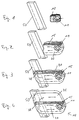
- FIGS The gas bag according to the invention is shown in FIGS different states.
- Fig. 1 you can see that ⁇ folded gas bag 10, for example in a Door trim of a motor vehicle is arranged.
- the gas bag 10 (see also FIG. 5) consists of two tabs 18, 20 made of tissue connected with a central lobe of tissue are made up of two sections 14, 16 and a middle one Strip 15 is made.
- the tab 18 there is an inlet opening for the in the event of a trigger by a (not shown)
- Gas generator developed gas for inflating the gas bag 10 formed in the middle strip 15 is a connection opening 38 formed by which one at the sewn Airbag 10 formed with first chamber 30 of the airbag 10 a second chamber 35 can communicate (see also Fig. 6).
- Fig. 1 In the folded state shown in Fig. 1 becomes the gas bag 10, the inflated shape of which in FIG. 4 see is transferred by the emptied spread Airbag essentially first along the partition 15 is folded lengthways so that the wall of the second chamber 35 is folded onto the wall of the first chamber 30. Then the wall of the two chambers is based on that of the inlet opening 11 facing away from the longitudinal end of the folded Wall 12 rolled up towards inlet opening 11. The result this folding can be seen in Fig. 1, in the left of the rolled-up part of the wall 12 to the inlet opening 11 see is. 1 is a vehicle B-pillar 50 shown that symbolizes part of the vehicle structure, which is of particular importance in the event of a side impact Is a danger to a vehicle occupant and therefore from one deployed gas bag must be covered.
- Airbag is the preferred direction of deployment further oriented so that the partition of the gas bag extends essentially horizontally in the inflated state.
- FIG. 2 shows the gas bag 10 with the first chamber partially unfolded 30 to see.
- a Gas generator through the inlet opening 11 in the gas bag 10 inflowing gas is symbolized by the arrows and first becomes the first chamber 30 along the preferred direction of deployment of the airbag 10 with the longitudinal direction the chamber agrees to deploy on the B pillar.
- Fig. 3 the airbag 10 is with the first fully deployed Chamber 30 can be seen.
- the end of the partition 15 is in particular the connection opening 38 to see through which the second chamber 35 the first chamber 30 communicates.
- This connection opening 38 is essentially only that shown in FIG. 3 Condition of the airbag released since it was previously closed by overlying wall parts of the gas bag 10 is. Since this connection opening 38 only then is released when the first chamber 30 substantially is fully deployed, the gas bag 10 during a first stage of the unfolding process essentially inflated only in the preferred direction of deployment, which is why he reaches a position particularly quickly, in which he provides initial protection for a vehicle occupant can train.
- the second chamber 35 becomes through the first chamber 30 and the connection opening 38 filled so that the Airbag its fully unfolded shown in Fig. 4 Maintains shape and full protection for a vehicle occupant can offer.
- the gas bag made from a single piece of fabric, in particular the partition 15 is part of this fabric part and therefore does not have to be sewn in separately.
- This piece of tissue is shown in Fig. 5.
- the fabric part from a first tab 18, a second Tab 20 and one arranged between these two tabs Middle lobe consists of a first section 14, a second section 16 and one between them lying middle strip 15 is formed.
- This streak 15 forms the partition in the sewn gas bag.
- Fig. 5 is also arranged in the first tab 18 Inlet opening 11 as well as that in the middle strip 15 arranged connection opening 38 to see.
- the gas bag is thereby formed from this part of the fabric (see also Fig. 6) that the first tab 18 so over the first Section 14 of the middle lobe is folded that a in the preferred direction of deployment, on the Second edge region lying on the side of the second tab 16 25 of the middle strip 15 of the middle lobe with one over the first section 14 edge region 23 of the first flap 18 can be sewn, being at the transition between the first tab 18 and the middle tab 14 a first in the preferred direction of deployment Fold line 40 arises, and that the second flap 20 then so folded over the second section 16 of the middle lobe is that a direction in the preferred direction of deployment the first lying on the side of the first flap 18 Edge region 21 of the middle strip 15 of the middle lobe with an edge region lying above the second section 16 27 of the second flap 20 can be sewn, whereby at the transition between the second lobe 20 and the middle lobe one in the preferred direction of deployment second fold line 42 is formed.
- first flap 18 or the second tab 20 with the outer edge of the first section 14 and the second section 16 of the middle flap, the fold line 40 or 42 at the transition between the first tab 18 and the second Tab 20 and the corresponding section 14 and 16 respectively of the middle lobe can be included in this seam, as can be seen in Fig. 6.
- the wall of the sewn gas bag due to this Production essentially in the form of an eight runs.
- the first chamber 30 and the second chamber 35 is essentially the same volume exhibit.
Landscapes
- Engineering & Computer Science (AREA)
- Mechanical Engineering (AREA)
- Air Bags (AREA)
Claims (7)
- Coussin d'air contre les chocs latéraux pour un système de retenue des passagers d'un véhicule, avec une paroi (12) dans laquelle est prévu un orifice d'entrée (11) pour gonfler le coussin d'air (10), et avec une cloison de séparation (15) à l'intérieur du coussin d'air, cloison qui subdivise l'intérieur du coussin d'air (10) en deux chambres voisines (30, 35), lesquelles peuvent être mises en liaison par un orifice de liaison (38), constitué dans la cloison de séparation (15), la paroi (12) du coussin d'air (10) étant repliée en position d'arrimage de façon à ne pas encombrer et le coussin d'air (10) se déployant lors du gonflage en partant de l'orifice d'entrée (11) essentiellement dans une direction privilégiée de déploiement, coussin d'air caractérisé en ce que les deux chambres (30, 35) sont allongées et leur direction longitudinale coïncide avec la direction privilégiée de déploiement, en ce que l'orifice d'entrée (11) est disposé à une première extrémité dans le sens de la longueur et l'orifice de liaison (38) est disposé à une seconde extrémité, dans le sens de la longueur, de la première chambre (30), et en ce que l'orifice de liaison (38), quand la paroi (12) est en position de repliement, est fermé par des éléments de paroi se trouvant au-dessus et quand la paroi (12) se déplie la première chambre (30) est libéré seulement en arrivant à proximité de la seconde extrémité, dans le sens de la longueur, de la première chambre (30).
- Coussin d'air selon la revendication 1, caractérisé en ce que la paroi (12), quand elle est en position d'arrimage, est repliée en direction de l'orifice d'entrée (11) par un pliage longitudinal sensiblement le long de la cloison de séparation (15) et en se mettant l'un sur l'autre, en partant de l'extrémité, dans le sens de la longueur, de la paroi repliée (12), située à l'opposé de l'orifice d'entrée (11).
- Coussin d'air selon la revendication 2, caractérisé en ce que la paroi (12) repliée dans le sens de la longueur est, en position d'arrimage, enroulée en direction de l'extrémité d'entrée.
- Coussin d'air selon la revendication 1, caractérisé en ce que la paroi (12) est fabriquée à partir d'une pièce de tissu unique, qui consiste en un premier et un second lés (18, 20) et un lé central (14, 15, 16), disposé entre eux, la cloison de séparation étant formée par une bande centrale (15) du lé du milieu (14, 15, 16), qui subdivise le lé du milieu (14, 15, 16) en une première et une seconde section (14, 16).
- Coussin d'air selon la revendication 4, caractérisé en ce que la paroi (12) s'étend dans une section transversale perpendiculairement à la direction privilégiée de déploiement en formant sensiblement un huit et en ce que le coussin d'air (10) est constitué à partir de la pièce de tissu d'une manière telle que le premier lé (18) est replié sur la première section (14) du lé du milieu et une deuxième zone de bordure (25), qui s'étend dans la direction privilégiée de déploiement et qui se trouve sur le côté du second lé (16), de la bande centrale (15) du lé du milieu, est cousue avec une zone de bordure (23) du premier lé (18), qui se trouve sur la première section (14), une première ligne de pliage (40), qui s'étend dans la direction privilégiée du déploiement, se produisant au passage entre le premier lé (18) et le lé du milieu (14), en ce que le second lé (20) est replié sur la seconde section (16) du lé du milieu et une première zone de bordure (21) de la bande centrale (15) du lé du milieu, zone de bordure qui s'étend dans le sens privilégié de déploiement et qui se trouve sur le coté du premier lé (18), est cousue avec une zone de bordure (27) du second lé (20), qui se trouve sur la seconde section (16), une seconde ligne de pliage (42), qui s'étend dans la direction privilégiée du déploiement, se produisant au passage entre le second lé (20) et le lé du milieu, et en ce que les bords extérieurs du coussin d'air (10) sont cousus ensemble.
- Coussin d'air selon l'une des revendications précédentes, caractérisé en ce que la cloison de séparation (15) s'étend de façon sensiblement horizontale et dans le sens de l'axe longitudinal du véhicule, quand le coussin d'air (10) est en position gonflée.
- Coussin d'air selon l'une des revendications précédentes, caractérisé en ce que la première et la seconde chambre (30, 35) présentent sensiblement le même volume.
Applications Claiming Priority (2)
| Application Number | Priority Date | Filing Date | Title |
|---|---|---|---|
| DE4443027A DE4443027A1 (de) | 1994-12-02 | 1994-12-02 | Seitenaufprall-Gassack |
| DE4443027 | 1994-12-02 |
Publications (2)
| Publication Number | Publication Date |
|---|---|
| EP0714818A1 EP0714818A1 (fr) | 1996-06-05 |
| EP0714818B1 true EP0714818B1 (fr) | 1999-01-27 |
Family
ID=6534802
Family Applications (1)
| Application Number | Title | Priority Date | Filing Date |
|---|---|---|---|
| EP95118875A Expired - Lifetime EP0714818B1 (fr) | 1994-12-02 | 1995-11-30 | Coussin gonflable pour collision latérale |
Country Status (9)
| Country | Link |
|---|---|
| US (1) | US5692774A (fr) |
| EP (1) | EP0714818B1 (fr) |
| JP (1) | JP2907556B2 (fr) |
| KR (1) | KR100231092B1 (fr) |
| CZ (1) | CZ225296A3 (fr) |
| DE (2) | DE4443027A1 (fr) |
| ES (1) | ES2087845T3 (fr) |
| PL (1) | PL315717A1 (fr) |
| WO (1) | WO1996016842A1 (fr) |
Families Citing this family (36)
| Publication number | Priority date | Publication date | Assignee | Title |
|---|---|---|---|---|
| US5566977A (en) * | 1995-06-01 | 1996-10-22 | Trw Vehicle Safety Systems Inc. | Air bag including restraint |
| DE29517372U1 (de) * | 1995-11-02 | 1996-02-01 | Trw Repa Gmbh | Gassack-Seitenaufprall-Schutzeinrichtung |
| JP3397041B2 (ja) * | 1996-03-28 | 2003-04-14 | 豊田合成株式会社 | 側突用エアバッグ |
| JP2962225B2 (ja) * | 1996-04-08 | 1999-10-12 | 三菱自動車工業株式会社 | 側面衝突用エアバッグ |
| DE29608055U1 (de) | 1996-04-24 | 1996-07-18 | Daimler Benz Ag | Gassack, insbesondere für ein Seitenairbagmodul |
| JP3016746B2 (ja) * | 1996-04-24 | 2000-03-06 | ペトリ・アーゲー | ガスバッグ |
| GB2317370B (en) * | 1996-09-21 | 1998-12-02 | Breed Automotive Tech | Apparatus for protecting a vehicle occupant |
| JP3430835B2 (ja) * | 1996-09-26 | 2003-07-28 | 三菱自動車工業株式会社 | エアバック装置 |
| DE19652019A1 (de) * | 1996-12-13 | 1998-06-18 | Takata Europ Gmbh | Luftsack für einen Seitenairbag |
| US5853191A (en) * | 1997-02-06 | 1998-12-29 | Alliedsignal Inc. | Vehicle restraint system with inflation control |
| DE29705133U1 (de) | 1997-03-20 | 1997-07-24 | Trw Repa Gmbh | Gassack für ein Fahrzeuginsassen-Schutzsystem |
| GB2324280A (en) * | 1997-04-18 | 1998-10-21 | Alliedsignal Deutschland Gmbh | A side impact airbag and a method of folding an airbag |
| DE19720585A1 (de) * | 1997-05-16 | 1998-11-19 | Porsche Ag | Seitenaufprallschutzeinrichtung für einen Insassen eines Fahrzeuges |
| DE19720584C2 (de) * | 1997-05-16 | 2000-11-23 | Porsche Ag | Seitenaufprallschutzeinrichtung für einen Insassen eines Fahrzeuges |
| DE19720588A1 (de) * | 1997-05-16 | 1998-11-19 | Porsche Ag | Aufprallschutzeinrichtung für einen Insassen eins Fahrzeuges |
| DE19720587A1 (de) * | 1997-05-16 | 1998-11-19 | Porsche Ag | Seitenaufprallschutzeinrichtung für einen Insassen eines Fahrzeuges |
| DE19720586C2 (de) * | 1997-05-16 | 2000-11-30 | Porsche Ag | Seitenaufprallschutzeinrichtung für einen Insassen eines Fahrzeuges |
| US5906391A (en) * | 1997-08-05 | 1999-05-25 | Takata, Inc. | Dual chamber airbag with improved assembly features |
| DE19860932A1 (de) * | 1998-12-30 | 2000-07-13 | Petri Ag | Airbagmodul |
| JP3474799B2 (ja) * | 1999-04-13 | 2003-12-08 | 日本プラスト株式会社 | エアバッグ |
| US20030168836A1 (en) * | 2002-03-11 | 2003-09-11 | Eiji Sato | Side airbag apparatus |
| JP3670249B2 (ja) * | 2002-04-12 | 2005-07-13 | 本田技研工業株式会社 | 車両外置きエアバッグ装置 |
| DE10236859A1 (de) | 2002-08-07 | 2004-02-19 | Takata Corp. | Gassack für ein Airbagmodul |
| JP4161705B2 (ja) * | 2002-12-19 | 2008-10-08 | タカタ株式会社 | サイドエアバッグ及びサイドエアバッグ装置 |
| JP4285167B2 (ja) * | 2003-01-30 | 2009-06-24 | タカタ株式会社 | 側突用エアバッグ装置 |
| JP2004243976A (ja) * | 2003-02-17 | 2004-09-02 | Takata Corp | 側突用エアバッグ装置 |
| JP4367119B2 (ja) * | 2003-05-07 | 2009-11-18 | タカタ株式会社 | エアバッグ及びエアバッグ装置 |
| GB2402912A (en) * | 2003-06-20 | 2004-12-22 | Autoliv Dev | Side air-bag |
| GB2403457A (en) * | 2003-06-30 | 2005-01-05 | Autoliv Dev | Improvements in or relating to an air-bag |
| US20060022439A1 (en) * | 2004-07-30 | 2006-02-02 | Trw Vehicle Safety Systems Inc. | Inflatable vehicle occupant protection device with differentially pressurized chambers |
| JP4345645B2 (ja) * | 2004-11-09 | 2009-10-14 | 豊田合成株式会社 | 膝保護用エアバッグ装置 |
| US7367586B2 (en) * | 2005-05-09 | 2008-05-06 | Ford Global Technologies, Llc | Airbag restraint for automotive vehicle |
| EP2008879B1 (fr) * | 2007-06-29 | 2012-06-27 | Dalphi Metal España, S.A. | Airbag latéral adaptatif à trois chambres |
| JP5259136B2 (ja) * | 2007-08-09 | 2013-08-07 | タカタ株式会社 | 側突用エアバッグ装置 |
| JP5278274B2 (ja) * | 2009-10-02 | 2013-09-04 | トヨタ紡織株式会社 | エアバッグ |
| GB2524292A (en) * | 2014-03-19 | 2015-09-23 | Ford Global Tech Llc | An airbag system |
Family Cites Families (8)
| Publication number | Priority date | Publication date | Assignee | Title |
|---|---|---|---|---|
| US4262931A (en) * | 1979-09-18 | 1981-04-21 | Ford Motor Company | Air bag restraint system |
| JP2754979B2 (ja) * | 1991-10-17 | 1998-05-20 | 日産自動車株式会社 | 自動車用エアバッグ装置 |
| JPH0544713U (ja) * | 1991-11-25 | 1993-06-15 | 株式会社東海理化電機製作所 | エアバツグ装置 |
| US5273309A (en) * | 1992-06-19 | 1993-12-28 | General Motors Corporation | Air bag for side impact |
| JPH06227348A (ja) * | 1993-02-05 | 1994-08-16 | Toyota Motor Corp | サイドエアバッグ装置 |
| US5454595A (en) * | 1994-09-08 | 1995-10-03 | Morton International, Inc. | Hidden volume cushion |
| US5586782A (en) * | 1995-06-26 | 1996-12-24 | Alliedsignal Inc. | Dual pressure side impact air bag |
| US5520413A (en) * | 1995-09-11 | 1996-05-28 | Morton International, Inc. | Partitioned multi-cell air bag |
-
1994
- 1994-12-02 DE DE4443027A patent/DE4443027A1/de not_active Withdrawn
-
1995
- 1995-11-30 ES ES95118875T patent/ES2087845T3/es not_active Expired - Lifetime
- 1995-11-30 PL PL95315717A patent/PL315717A1/xx unknown
- 1995-11-30 JP JP8518202A patent/JP2907556B2/ja not_active Expired - Fee Related
- 1995-11-30 EP EP95118875A patent/EP0714818B1/fr not_active Expired - Lifetime
- 1995-11-30 CZ CZ962252A patent/CZ225296A3/cs unknown
- 1995-11-30 DE DE59504975T patent/DE59504975D1/de not_active Expired - Fee Related
- 1995-11-30 US US08/693,156 patent/US5692774A/en not_active Expired - Fee Related
- 1995-11-30 WO PCT/EP1995/004731 patent/WO1996016842A1/fr not_active Ceased
-
1996
- 1996-07-30 KR KR1019960704111A patent/KR100231092B1/ko not_active Expired - Fee Related
Also Published As
| Publication number | Publication date |
|---|---|
| KR100231092B1 (en) | 1999-11-15 |
| ES2087845T1 (es) | 1996-08-01 |
| US5692774A (en) | 1997-12-02 |
| DE59504975D1 (de) | 1999-03-11 |
| DE4443027A1 (de) | 1996-06-05 |
| JPH09501888A (ja) | 1997-02-25 |
| ES2087845T3 (es) | 1999-06-01 |
| CZ225296A3 (en) | 1997-02-12 |
| PL315717A1 (en) | 1996-11-25 |
| KR970700605A (ko) | 1997-02-12 |
| EP0714818A1 (fr) | 1996-06-05 |
| JP2907556B2 (ja) | 1999-06-21 |
| WO1996016842A1 (fr) | 1996-06-06 |
Similar Documents
| Publication | Publication Date | Title |
|---|---|---|
| EP0714818A1 (fr) | Coussin gonflable pour collision latérale | |
| EP0495409B1 (fr) | Coussin d'air gonflable pour un système de retenue dans des véhicules | |
| DE60023205T2 (de) | Luftsack | |
| EP0771699B1 (fr) | Dispositif de protection contre les chocs latéraux à coussin gonflable, pour occupants de véhicules | |
| DE19714267B4 (de) | Seitenaufprall-Airbagsystem | |
| EP0974498B1 (fr) | Système de retenue à sac de sécurité gonflable | |
| EP0771698B1 (fr) | Dispositif de protection contre les chocs latéraux à coussin gonflable | |
| DE19964446B4 (de) | Beifahrersitz-Airbagsystem | |
| DE102009019930A1 (de) | Gassackmodul zum Schutz des Thorax- und Kopfbereichs eines Fahrzeuginsassen | |
| DE4116162A1 (de) | Sicherheitsgurt fuer fahrzeugsitze, insbesondere kraftfahrzeugsitze | |
| EP0936981B1 (fr) | Sac a gaz pour un module airbag, et procede et dispositif de pliage d'un sac a gaz | |
| DE10063473B4 (de) | Dachholm-Verkleidung für aufblasbares Rückhaltesystem | |
| DE10045667A1 (de) | Airbageinrichtung | |
| EP2582551A2 (fr) | Ensemble coussin de sécurité pour les genoux pour véhicules | |
| DE102005041085A1 (de) | Vorhang-Airbag für Fahrzeuge | |
| DE4138645A1 (de) | Airbag fuer eine kraftfahrzeug-sicherheitsvorrichtung | |
| DE4439259A1 (de) | Luft- bzw. Gassackeinrichtung | |
| EP0453740B1 (fr) | Dispositif de logement pour sac à air | |
| DE102017108493B4 (de) | Kniegassackmodul und Verfahren zum Packen eines Kniegassackes in ein Gehäuse | |
| DE10246769A1 (de) | Seitenaufprall-Schutzvorrichtung | |
| DE4439267A1 (de) | Luft bzw. Gassack | |
| DE102019216887A1 (de) | Gassackmodul für ein Kraftfahrzeug | |
| EP0992404B1 (fr) | Dispositif de coussin de sécurité | |
| DE10204486A1 (de) | Schutzeinrichtung für Insasssen von Kraftfahrzeugen | |
| DE19837897B4 (de) | Aufblasbarer Luftsack für Kraftfahrzeuge |
Legal Events
| Date | Code | Title | Description |
|---|---|---|---|
| PUAI | Public reference made under article 153(3) epc to a published international application that has entered the european phase |
Free format text: ORIGINAL CODE: 0009012 |
|
| AK | Designated contracting states |
Kind code of ref document: A1 Designated state(s): DE ES FR GB IT SE |
|
| REG | Reference to a national code |
Ref country code: ES Ref legal event code: BA2A Ref document number: 2087845 Country of ref document: ES Kind code of ref document: T1 |
|
| GBC | Gb: translation of claims filed (gb section 78(7)/1977) | ||
| EL | Fr: translation of claims filed | ||
| REG | Reference to a national code |
Ref country code: ES Ref legal event code: BA2A Ref document number: 2087845 Country of ref document: ES Kind code of ref document: T1 |
|
| 17P | Request for examination filed |
Effective date: 19960812 |
|
| RAP1 | Party data changed (applicant data changed or rights of an application transferred) |
Owner name: TRW OCCUPANT RESTRAINT SYSTEMS GMBH & CO. KG |
|
| GRAG | Despatch of communication of intention to grant |
Free format text: ORIGINAL CODE: EPIDOS AGRA |
|
| GRAH | Despatch of communication of intention to grant a patent |
Free format text: ORIGINAL CODE: EPIDOS IGRA |
|
| 17Q | First examination report despatched |
Effective date: 19980609 |
|
| GRAH | Despatch of communication of intention to grant a patent |
Free format text: ORIGINAL CODE: EPIDOS IGRA |
|
| GRAA | (expected) grant |
Free format text: ORIGINAL CODE: 0009210 |
|
| AK | Designated contracting states |
Kind code of ref document: B1 Designated state(s): DE ES FR GB IT SE |
|
| PG25 | Lapsed in a contracting state [announced via postgrant information from national office to epo] |
Ref country code: SE Free format text: THE PATENT HAS BEEN ANNULLED BY A DECISION OF A NATIONAL AUTHORITY Effective date: 19990127 |
|
| ITF | It: translation for a ep patent filed | ||
| GBT | Gb: translation of ep patent filed (gb section 77(6)(a)/1977) |
Effective date: 19990128 |
|
| REF | Corresponds to: |
Ref document number: 59504975 Country of ref document: DE Date of ref document: 19990311 |
|
| ET | Fr: translation filed | ||
| REG | Reference to a national code |
Ref country code: ES Ref legal event code: FG2A Ref document number: 2087845 Country of ref document: ES Kind code of ref document: T3 |
|
| PLBE | No opposition filed within time limit |
Free format text: ORIGINAL CODE: 0009261 |
|
| STAA | Information on the status of an ep patent application or granted ep patent |
Free format text: STATUS: NO OPPOSITION FILED WITHIN TIME LIMIT |
|
| 26N | No opposition filed | ||
| PGFP | Annual fee paid to national office [announced via postgrant information from national office to epo] |
Ref country code: GB Payment date: 20001004 Year of fee payment: 6 |
|
| PGFP | Annual fee paid to national office [announced via postgrant information from national office to epo] |
Ref country code: FR Payment date: 20011105 Year of fee payment: 7 |
|
| PGFP | Annual fee paid to national office [announced via postgrant information from national office to epo] |
Ref country code: ES Payment date: 20011121 Year of fee payment: 7 |
|
| PG25 | Lapsed in a contracting state [announced via postgrant information from national office to epo] |
Ref country code: GB Free format text: LAPSE BECAUSE OF NON-PAYMENT OF DUE FEES Effective date: 20011130 |
|
| REG | Reference to a national code |
Ref country code: GB Ref legal event code: IF02 |
|
| GBPC | Gb: european patent ceased through non-payment of renewal fee |
Effective date: 20011130 |
|
| PG25 | Lapsed in a contracting state [announced via postgrant information from national office to epo] |
Ref country code: ES Free format text: LAPSE BECAUSE OF NON-PAYMENT OF DUE FEES Effective date: 20021201 |
|
| PG25 | Lapsed in a contracting state [announced via postgrant information from national office to epo] |
Ref country code: FR Free format text: LAPSE BECAUSE OF NON-PAYMENT OF DUE FEES Effective date: 20030731 |
|
| REG | Reference to a national code |
Ref country code: FR Ref legal event code: ST |
|
| PGFP | Annual fee paid to national office [announced via postgrant information from national office to epo] |
Ref country code: DE Payment date: 20031128 Year of fee payment: 9 |
|
| REG | Reference to a national code |
Ref country code: ES Ref legal event code: FD2A Effective date: 20031213 |
|
| PG25 | Lapsed in a contracting state [announced via postgrant information from national office to epo] |
Ref country code: DE Free format text: LAPSE BECAUSE OF NON-PAYMENT OF DUE FEES Effective date: 20050601 |
|
| PG25 | Lapsed in a contracting state [announced via postgrant information from national office to epo] |
Ref country code: IT Free format text: LAPSE BECAUSE OF NON-PAYMENT OF DUE FEES Effective date: 20051130 |