EP0715164A2 - Appareil de contrÔle de faces latérales d'articles pressés, convoyeur pour articles pressés, et appareil de contrÔle de l'apparence d'articles pressés - Google Patents
Appareil de contrÔle de faces latérales d'articles pressés, convoyeur pour articles pressés, et appareil de contrÔle de l'apparence d'articles pressés Download PDFInfo
- Publication number
- EP0715164A2 EP0715164A2 EP95118538A EP95118538A EP0715164A2 EP 0715164 A2 EP0715164 A2 EP 0715164A2 EP 95118538 A EP95118538 A EP 95118538A EP 95118538 A EP95118538 A EP 95118538A EP 0715164 A2 EP0715164 A2 EP 0715164A2
- Authority
- EP
- European Patent Office
- Prior art keywords
- pressed articles
- pockets
- pressed
- cross
- section
- Prior art date
- Legal status (The legal status is an assumption and is not a legal conclusion. Google has not performed a legal analysis and makes no representation as to the accuracy of the status listed.)
- Withdrawn
Links
Images


Classifications
-
- G—PHYSICS
- G01—MEASURING; TESTING
- G01N—INVESTIGATING OR ANALYSING MATERIALS BY DETERMINING THEIR CHEMICAL OR PHYSICAL PROPERTIES
- G01N21/00—Investigating or analysing materials by the use of optical means, i.e. using sub-millimetre waves, infrared, visible or ultraviolet light
- G01N21/84—Systems specially adapted for particular applications
- G01N21/88—Investigating the presence of flaws or contamination
- G01N21/95—Investigating the presence of flaws or contamination characterised by the material or shape of the object to be examined
- G01N21/9508—Capsules; Tablets
Definitions
- This invention relates to a side face examination apparatus for pressed articles such as tablets having a substantially circular cross-section, a conveyor for pressed articles which is suitable to the side face examination apparatus, and an external appearance examination apparatus for pressed articles using the side face examination apparatus and the conveyor.
- FIG. 12(a) is a plan view of a first tablet when the circular cross-section is horizontal.
- FIG. 12(b) is a side view of the first tablet shown in FIG.12(a).
- FIG.13 (a) is a plan view of a second tablet when the circular cross-section is horizontal.
- FIG.13(b) is a side view of the second tablet shown in FIG.13(a).
- a cross-section perpendicular to the circular cross-section has substantially elliptical shape.
- a cross-section perpendicular to the circular cross-section has substantially rectangular shape, so that the side face of second tablet is cylindrical.
- the whole external appearance of the second tablet can not be examined from two directions shown by arrows A and B in FIG.13(b). It is necessary to examine the external appearance of the second tablet further from a direction shown by arrow C.
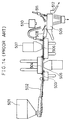
- a conventional external appearance examination apparatus for pressed articles for example, shown in Publication Gazette of Unexamined Japanese Patent Application Hei 2-107383, which can examine the external appearance of the pressed article from the above-mentioned three directions shown by arrows A, B and C, is described referring to FIG.14.
- the pressed articles supplied from a hopper 501 are arranged by an arranging apparatus 502 in a manner so that the direction of the circular cross-section of the pressed articles becomes horizontal.
- the arranged pressed articles are conveyed in a horizontal direction by a conveyor 503.
- the pressed articles are held on a suction conveyor 504 by suction force of negative pressure.
- the posture of the pressed articles are changed by a posture changing apparatus 508 in a manner so that the circular cross-section becomes vertical.
- the pressed articles are rotated by the rotation apparatus 509 under a condition that the circular cross-section is vertical
- picture images of side faces of the pressed articles are taken by an image pickup apparatus 510. If the appearance is found to be inferior on at least one of the front, rear and side faces, the pressed article is judged as an inferior article.
- the inferior article is removed by an inferior article removing apparatus 511. Excellent articles, which are not found to be inferior in appearance, are conveyed to next stage from a shoot 512.
- the pressed articles contained in the hopper 501 are arranged in a condition that the circular cross-section becomes horizontal for examining the rear and front surfaces of the pressed articles.
- the posture of the pressed articles are converted to another condition that the circular cross-section is vertical by the posture changing apparatus 508 for examining the side faces of the pressed articles.
- the hopper 501, the arranging apparatus 502, the conveyor 504, 506, the posture changing apparatus 508, the rotation apparatus 509, the shoot 512 are arranged in the horizontal direction.
- the above-mentioned conventional apparatus has a problem that a width of the apparatus becomes wider in a horizontal direction.
- the external appearance examination apparatus is generally disposed in a clean room. If the space of the clean room is not so wide, the apparatus occupying a wide space in a horizontal direction wastes valuable space of the clean room. Thus, the width of the apparatus, which is to be disposed in the clean room, should be narrower.
- guide rails having substantially the same width as the diameter of the pressed articles are generally used as a conventional conveyor for conveying the pressed articles in an arranged condition.
- slats with pockets having substantially the same size of the articles are used for conveying the pressed articles.
- the conveyors 504, 506 and the image pickup apparatuses 505, 507 which are used for observing the front and rear surfaces of the pressed articles, have generally well-known configurations. Therefore, there is an opportunity that the side face examination apparatus of the pressed articles, which is configured by the posture changing apparatus 508, the rotation apparatus 509 and the image pickup device 510 and so on, is used in combination with another apparatus different from the above-mentioned conveyors 504, 506 and the image pickup apparatuses 505, 507. Alternatively, there is an opportunity that the side face examination apparatus is used independently. However, a precondition of the use of the side face examination apparatus, the pressed articles supplied to the posture changing apparatus 508 must be arranged in the horizontal direction, previously. Namely, the conventional side face examination apparatus can not examine the pressed articles which are supplied at random.
- This invention is to solve the above-mentioned problems of the prior art, and aims to provide a simply configured and compact side face examination apparatus for pressed articles which can examine the side faces of the pressed articles directly received at random from a hopper or the like, to provide a conveyor for pressed articles which can convey the articles with no relation to the size of the articles to be conveyed, and to provide an external appearance examination apparatus for pressed articles using them.
- a side face examination apparatus for pressed articles of this invention comprises: an arranging apparatus for arranging pressed articles, which are supplied at random, in a manner so that a cross-section of a pressed article having a largest area is substantially vertical, and having a plurality of guide grooves having a width wider by a predetermined tolerance than a width of the pressed article in a direction perpendicular to the cross-section; a conveying drum intermittently rotated around a horizontal axis, and having pockets arranged for facing the guide grooves and holding the pressed articles, which are arranged by the arranging apparatus, in a manner so that the cross-section is substantially vertical; a pressed article rotating roller disposed at a predetermined position in the inside of the conveying drum, and rotating the pressed articles in the pockets stopped at the predetermined position more than one turn around horizontal axes; and an image pickup apparatus disposed for facing an outer surface of the conveying drum at the predetermined position, and picking up picture images of side faces of
- the side face examination apparatus for pressed articles of this invention configured above, since the width of the guide grooves of the arranging apparatus is wider a predetermined tolerance than the width of the pressed articles in the direction perpendicular to the direction where the pressed articles have the largest cross-sectional area, the pressed articles, which are supplied at random, are arranged in the guide grooves in a manner so that the cross-section having the largest area is substantially vertical.
- the arranged pressed articles are transferred to the pockets which are arranged for facing the guide grooves, and intermittently conveyed by rotation around the horizontal axis under a condition that the cross-section having the largest area is substantially vertical.
- the pressed articles in the pockets stopped at the predetermined position are rotated more than one turn around the horizontal axis by the pressed article rotating roller, so that the whole side faces of the pressed articles are observed by the image pickup apparatus.
- the examination of the side face of the pressed articles becomes easy.
- the pressed article rotating roller is disposed in the inside of the conveying drum, and the image pickup apparatus is disposed for facing the conveying drum, the size of the apparatus in a horizontal direction is not much larger than the size of the conveying drum, and the configuration of the side face examination apparatus for pressed articles becomes simple and compact.
- the conveying drum comprises a fixed hollow inner sleeve and an outer sleeve rotatably engaged with an outer surface of the inner sleeve with a predetermined tolerance; the pockets are provided on the outer sleeve; connection holes or slits are provided at portions of the inner sleeve facing the guide grooves; and the inside of the inner sleeve is connected to a vacuum suction apparatus. Therefore, the pressed articles arranged in the guide grooves are transferred to the pockets one by one from the lowest point by the negative pressure. The omission of the pocket, in which a pressed article is not contained, hardly ever occurs.
- the pressed article rotating roller is rotatably borne on the inner sleeve, and has a plurality of larger diameter portions corresponding to the arrangement of the pockets, the larger diameter portions are protruded from the outer periphery of the inner sleeve. Therefore, the side faces of the pressed articles are largely protruded from the outer surface of the outer sleeve in the examination of the side faces. The side faces of the pressed articles are easily distinguished from the pockets or the outer surface of the outer sleeve in the displayed picture image.
- a width of the larger diameter portions of the pressed article rotating roller in a direction parallel to a rotation axis thereof is wider than a width of the pockets in that direction, and centers of the larger diameter portions are inconsistent with centers of the pockets. Therefore, the larger diameter portion covers the bottom of the pocket. Furthermore, there is a difference between lengths of air paths from both sides of the larger diameter portion to the center of the pocket. Thereby, a differential pressure is generated by the difference of the lengths in the air paths. The pressed article is pushed on an edge of the pocket in the air path of shorter length by the differential pressure. Accordingly, by standardizing the edge on which the pressed article is pushed, the quality judgement in the examination of the side face can be made easier.
- openings of the pockets are formed substantially as parallelograms, a pair of parallel sides are parallel to the rotation axis of the conveying drum and the other parallel sides are inclined against the rotation axis of the conveying drum. Therefore, the pressed article is pushed on the rear end face against the conveying direction (rotating direction of the conveying drum). As a result, by standardizing the end face on which the pressed article is pushed, the quality judgement in the examination of the side face can be made easier.
- each of the guide grooves of the arranging apparatus includes a slanted portion and a straight portion, wherein a width in the slanted portion becomes gradually narrower when the position progresses downward, a width in the straight portion is a width wider by a predetermined tolerance than a width of the pressed articles in a direction perpendicular to the cross-section having the largest area, and a vibration is applied to the arranging apparatus. Therefore, the pressed articles, which are supplied at random, can easily be arranged in the guide grooves.
- a conveyor for pressed articles of this invention comprises: a conveying drum having an equilateral polygonal cross-section in a vertical direction, and rotated around a horizontal axis; and connection holes provided at predetermined positions on each side of the equilateral polygon for holding pressed articles by negative pressure via the connection holes in a manner so that a cross-section of the pressed article having a largest area is substantially parallel to the horizontal axis. Therefore, many kinds of pressed articles can be conveyed by the same conveying drum, regardless of the sizes of the pressed articles.
- another conveyor for pressed articles of this invention comprises: a conveying drum having an equilateral polygonal cross-section in a vertical direction, and rotated around a horizontal axis; and connection holes and wide use pockets provided at predetermined positions on each side of the equilateral polygon for holding pressed articles by negative pressure via the connection holes in the pockets in a manner so that a cross-section of the pressed article having a largest area of the pressed articles is substantially parallel to the horizontal axis. Therefore, many kinds of pressed articles can be conveyed by the same conveying drum, regardless of the sizes of the pressed articles.
- each wide use pocket has a portion parallel to a rotation direction of the conveying drum and a substantially V-letter shaped portion having an apex angle of substantially 90 degrees which has an apex at a point distant a predetermined distance from center of the connection hole in the rotation direction. Therefore, a side face of the pressed article contacts edges of the V-letter shaped portion, and the connection hole positions in the vicinity of the center of the pressed article, regardless of the sizes of the pressed articles.
- the pressed articles are stably held in the wide use pocket by absorption of the negative pressure via the connection hole.
- the wide use pockets are formed on a block having a substantially rectangular cross-section in each direction, and each block is interchangeably fixed on a side of the equilateral polygon of the conveying drum. Therefore, many kinds of pressed articles having different sizes can be conveyed by the same conveyor when several kinds of the blocks respectively having different size of wide use pocket are prepared.
- Still another conveyor for pressed articles of this invention comprises: an arranging apparatus for arranging pressed articles, which are supplied at random, in a manner so that a cross-section of the pressed article having a largest area is substantially vertical, and having a plurality of guide grooves which have a width wider by a predetermined tolerance than a width of the pressed articles in a direction perpendicular to the cross-section; a first conveying drum intermittently rotated around a horizontal axis, and having first pockets arranged for facing the guide grooves and holding the pressed articles, which are arranged by the arranging apparatus, in a manner so that the cross-section of the pressed article having alargest area is substantially vertical; a posture changing apparatus disposed below the first conveying drum, having second pockets arranged for facing the first pockets, and changing posture of the pressed articles in a manner so that a direction of the cross-section of the pressed article having the largest area is changed from substantially vertical to substantially horizontal; and a second conveying apparatus disposed below the posture changing apparatus, having an
- the pressed articles which are supplied at random, can be arranged and conveyed in a manner so that the cross-section having the largest area is substantially parallel to the rotation axis of the conveying drum. Furthermore, the arranging apparatus, the first conveying drum, the posture changing apparatus and the second conveying drum are arranged in a substantially vertical direction, so that the size of the apparatus in the horizontal direction is not so much larger than the size of the conveying drum.
- the configuration of the conveyor for pressed articles becomes simple and compact.
- the afore-mentioned conveying drum having the wide use pockets can be used as the second conveying drum in the above-mentioned conveyor for pressed articles. Therefore, many kinds of the pressed articles can be conveyed by the same conveying drum, regardless of the sizes of the pressed articles.
- the posture changing apparatus comprises a rotating drum rotating around a horizontal axis and having the second pockets, and a guide plate provided for facing an outer surface of the drum with a predetermined tolerance, the guide plate has slanted grooves which contacts pressed articles protruded from the second pockets and slanted from a position on an upper end of the guide plate where the second pockets are not covered to a position where the second pockets are completely covered. Therefore, when the drum rotates around the horizontal axis, the pressed articles, which are protruded from the second pockets, contact the slanted edges of the grooves of the guide plate. When the drum further rotates, the pressed articles gradually fall sideways in the axial direction, and finally the posture of the pressed articles can be changed in a manner so that the cross-section of the largest area is substantially horizontal.
- an external appearance examination apparatus for pressed articles of this invention comprises the afore-mentioned arranging apparatus, the conveying drums, the pressed article rotating roller, the image pickup apparatuses, and the posture changing apparatus. Therefore, the external appearance examination apparatus for pressed articles operates the operations of the above-mentioned side face examination apparatus for pressed articles and conveyor for pressed articles. Furthermore, the posture changing apparatus is disposed below the first conveying drum. The posture of the pressed articles can be changed in a manner so that a direction of the cross-section having the largest area is changed to substantially horizontal from substantially vertical. The second conveying drum is disposed below the posture changing apparatus, and the third conveying drum is disposed below the second conveying drum.
- the front and rear surfaces of the pressed articles which are conveyed by the second and third conveying drums are examined by the second and third image pickup apparatuses. Not only the side face but also the front and rear surfaces of the pressed articles can be examined. Furthermore, the arranging apparatus, the first conveying drum, the posture changing apparatus, the second conveying drum, the third conveying drum and the inferior article removing apparatus are arranged in substantially vertical direction, so that the size of the apparatus in the horizontal direction is not so much larger than the size of the conveying drum.
- the configuration of the external appearance examination apparatus becomes simple and compact.
- an inferior article removing apparatus which is disposed below the third conveying drum, has third pockets provided at positions facing the second connection holes or the second wide use pockets and having an area larger than a largest cross-sectional area of the pressed articles and has third connection holes provided in the third pockets for blasting a compressed air. Therefore, an inferior article in which an inferior is found on at least one of the side face, first and second surface can be removed by blasting the compressed air through the third connection hole.
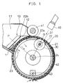
- FIG.1 is a cross-sectional side view showing a configuration of the side face examination apparatus for pressed articles
- FIG.2 is a cross-sectional view taken along line O-P in FIG.1
- FIG.3 is a cross-sectional view taken along line O-Q in FIG.1.
- the side face examination apparatus for pressed articles of this invention comprises an arranging apparatus 10, a conveying drum 20, a pressed article rotating roller 30, an image pickup apparatus 40, a brush roller 41 and a guide plate 42.
- the arranging apparatus 10 has a container portion 11 for containing pressed articles 1 which are supplied from a hopper or the like (not shown in the figure) at random.
- a plurality of guide grooves 12 are formed at the bottom of the container portion 11 and arranged in a horizontal direction.
- each guide groove 12 has a slanted portion 12a and a straight portion 12b.
- a width at an upper end is the widest and the width becomes gradually narrower when a position progresses downward.
- the width is a predetermined constant value which is wider by a predetermined tolerance than a width of the pressed articles 1 in a direction perpendicular to a cross-section having the largest cross-sectional area.
- the conveying drum 20 is comprised of a fixed hollow inner sleeve 21, a rotatable outer sleeve 22 and a rotation shaft 24.
- the inner sleeve 21 has a cylindrical outer surface and is held in a manner so that a center axis becomes horizontal.
- the outer sleeve 22 has a cylindrical shape and engages with an outer surface 21a of the inner sleeve 21 with a predetermined tolerance.
- the rotation shaft 24 is borne in a horizontal direction for bearing the rotation of the outer sleeve 22 in a vertical plane.
- An inside 21b of the inner sleeve 21 is connected to a vacuum suction apparatus (not shown in the figure) via a connection pipe 21c.
- slits 23 are formed at portions of the inner sleeve 21 which face the guide grooves 12.
- a plurality of lines of pockets 22b are arranged on an outer surface 22a of the outer sleeve 22 for facing the guide grooves 12 of the arranging apparatus 10.
- air flows which flow from the guide grooves 12 through the pockets 22b, connection holes or slits 23, inside 21b of the inner sleeve 21, and the connection pipe 21c, are generated.
- the pressed articles 1 arranged in the guide grooves 12 are transferred to the pockets 22b one by one at the bottom by negative pressure.
- Each pocket 22b holds the pressed article 1 in a manner so that the cross-section having the largest cross-sectional area becomes substantially vertical and a direction perpendicular to the cross-section is substantially parallel to the rotation axis of the rotation shaft 24. As a result, omission of the pressed article 1 in the pocket 22 will not occur.
- the brush roller 41 is disposed for contacting the outer surface 22a of the outer sleeve 22 for removing surplus pressed articles 1 getting on the outer surface 22a of the outer sleeve 22.
- the guide plate 42 which is disposed outside the outer sleeve 22 with a predetermined gap, guides the pressed articles 1 so as not to drop out from the pocket 22b by gravity.
- a compressed air blasting apparatus 43 is provided at a bottom portion in an inside of the conveying drum 20 for forcibly transferring the pressed articles 1 which are conveyed by the conveying drum 20 to another apparatus.
- the conveying drum 20 is intermittently rotated in a predetermined direction by a predetermined angles by a driving mechanism which is not shown in the figure.
- the pressed article rotating roller 30 is disposed at a predetermined position in the inside of the conveying drum 20, and a rotation shaft 31 in a horizontal direction is rotatably borne by the inner sleeve 21 and a fixed block 25.
- the rotation shaft 31 and the pressed article rotating roller 30 are independent from the conveying drum 20, and they are continuously rotated in a predetermined direction by another driving mechanism not shown in the figure.
- the pressed article rotating roller 30 has a plurality of larger diameter portions 32 which are disposed corresponding to the lines of the pockets 22b and protruded outside the outer surface 21a of the inner sleeve 21. Accordingly, the side face of the pressed article 1 in the pocket 22b stopping at the above-mentioned predetermined position is protruded outside the outer surface 22a of the outer sleeve 22. Furthermore, the pressed article 1 is rotated in the predetermined direction by the pressed article rotating roller 30.
- the image pickup apparatus 40 is disposed at a position facing the larger diameter portions 32 of the pressed article rotating roller 30.
- the image pickup apparatus 40 takes a picture image of the side faces of the pressed articles 1 rotated by the pressed article rotating roller 30.
- the pressed article rotating roller 30 rotates the pressed articles 1 more than one turn, while the conveying drum 20 stops in the intermittent movement.
- the whole side faces of the pressed articles 1 can be observed.
- the side faces of the pressed articles 1 can easily be distinguished from the pocket 22b or the outer surface 22a of the outer sleeve 22 in a picture image taken by the image pickup apparatus 40.
- a width of the larger diameter portion 32 of the pressed article rotating roller 30 in a direction of the shaft 31 is wider than a width of the pocket 22b for covering an opening at the bottom of the pocket 22b.
- the center of the larger diameter portions 32 and the center of the pocket 22b are inconsistent with each other.
- lengths of air paths flown from both sides of the larger diameter portion 32 to the center of the pocket 22b becomes different.
- a differential pressure is generated between air flows in the air paths.
- the pressed article 1 is pushed on an edge of the pocket 22b which is positioned in a shorter air path.
- the shape of the opening of the pocket 22b is a parallelogram.
- a pair of parallel sides are parallel to the rotation shaft 24, and the other parallel sides are inclined against the rotation direction of the conveying drum 20.
- the pressed article 1 is pushed on the rear edge in the rotating direction of the conveying drum 20.
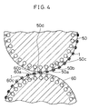
- FIG.4 is a cross-sectional side view of the conveyor for pressed articles
- FIG.5 is an enlarged cross-sectional side view of a main part thereof.
- vertical cross-sections of conveying drums 50 and 60 in the conveyor for pressed articles are respectively equilateral polygons.
- connection hole 50b or 60b is provided at a position facing, for example, the pocket 22b of the conveying drum 20 in the above-mentioned side face examination apparatus for pressed articles.
- the conveying drums 50 and 60 are respectively rotatably borne around horizontal axes. The rotation of the conveying drums 50 and 60 is acceptable to be continuous or intermittent, if the movement of the sides 50a and 60a or the connection holes 50b or 60b are synchronized.
- connection holes 50b and 60b are respectively connected to connection pipes 50c and 60c which are provided parallel to the rotation axes of the conveying drums 50 and 60.
- the connection pipes 50c and 60c are respectively connected to a vacuum suction apparatus not shown in the figure. Accordingly, the pressed articles 1 are sucked and held on the sides 50a and 60a of the equilateral polygons by negative pressure via the connection holes 50b and 60b and connection pipes 50c and 60c in a manner so that the cross-section of the pressed article 1 having the largest cross-sectional area is substantially parallel to the rotation axes of the conveying drums 50 and 60.
- the negative pressure in the connection hole 50c at the lowest portion 50d is released.
- the pressed article 1 falls by gravity to be transferred to the conveying drum 60.
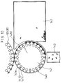
- FIG.6 is a cross-sectional side view showing the conveyor for pressed articles
- FIG.7 is a plan view showing a block 100 in FIG.6.
- vertical cross-sections of conveying drums 70 and 80 are respectively equilateral polygons.
- the block 100 having wide use pockets 101 is fixed on each side 70a or 80a of the equilateral polygon of the conveying drum 70 or 80.
- the wide use pockets 101 and connection holes 102 are provided at positions for facing, for example, the pockets 22b of the conveying drum 20 in the above-mentioned side face examination apparatus for pressed articles.
- the conveying drums 70 and 80 are respectively rotatably borne around horizontal axes.
- the rotation of the conveying drums 70 and 80 is acceptable to be continuous or intermittent, if the movement of the sides 70a and 80a or the wide use pockets 101 or connection holes 102 of the blocks 100 are synchronized.
- connection holes 70b and 80b which are respectively connected to the connection holes 102 of the blocks 100, and connection pipes 70c and 80c, which are provided in axial direction, are provided on the conveying drums 70 and 80.
- the connection pipes 70c and 80c are respectively connected to a vacuum suction apparatus not shown in the figure.
- the pressed articles 1 are sucked and held in the wide use pockets 101 by negative pressure via the connection holes 70b and 80b, the connection pipes 70c and 80c and the connection holes 102 in a manner so that the cross-section of the pressed article 1 having the largest cross-sectional area is substantially parallel to the rotation axes of the conveying drums 70 and 80.
- the conveying drum 70 disposed above the conveying drum 80 when the pressed article 1 held in the wide use pocket 101 reaches to a lowest position 70d, the negative pressure in the connection hole 102 of the block 100 at the lowest portion 70d is released. Thus, the pressed article 1 falls from the wide use pocket 101 by gravity to be transferred to the conveying drum 80.
- each wide use pocket 101 has a portion 101a having sides parallel to the rotation direction of the conveying drums 70 and 80 (shown by arrow Y) and a substantially V-letter shaped portion 101b having an apex angle of about 90 degrees.
- the apex of the V-letter shaped portion 101b is distant a predetermined distance from the center of the connection hole 102 in the rotation direction shown by arrow Y.
- a side opposite to the V-letter shaped portion 101b is opened.
- connection hole 102 is positioned in the vicinity of the center of the pressed article 1 regardless of the size of the pressed article 1.
- the pressed article 1 can stably be held in the wide use pocket 101 by negative pressure via the connection hole 102.
- the wide use pockets 101 are formed on the block 100, and the block 100 is interchangeably mounted on each side 70a or 80a of the equilateral polygon of the conveying drum 70 or 80.
- the blocks 100 respectively having different sizes of wide use pockets 101 are prepared, many kinds of pressed articles respectively having largely different sizes can be conveyed by the same conveyor.
- the conveyor for pressed articles comprises at least the conveying drum 50 or 70
- a plane conveyor such as a belt conveyor, slats and so on can be used instead of the other conveying drum 60 or 80.
- FIG.8 is a perspective view of the conveyor.
- the conveyor comprises an arranging apparatus 10, a first conveying drum 20, a posture changing apparatus 110, and a second conveying drum 50.
- the arranging apparatus 10 arranges the pressed articles 1, which are supplied at random, in a manner so that the cross-section having the largest cross-sectional area is substantially vertical.
- the first conveying drum 20 is disposed for facing the arranging apparatus 10 and intermittently rotated around a horizontal axis.
- the arranging apparatus 10 and the first conveying drum 20 are substantially the same as those of the above-mentioned side face examination apparatus for pressed articles shown in FIGs. 1 to 3, but the pressed articles rotating roller 30 and the image pickup apparatus 40 are omitted.
- the posture changing apparatus 110 receives the pressed article 1 from the first conveying drum 20 in a posture such that the cross-section having the largest cross-sectional area is substantially vertical, and changes the posture of the pressed article 1 to another posture in which the cross-section having the largest area is substantially horizontal.
- the second conveying drum 50 is disposed below the posture changing apparatus 110, rotated around a horizontal axis.
- the second conveying drum 50 receives the pressed articles from the posture changing apparatus 110 in the posture that the cross-section having the largest cross-section is substantially horizontal, and holds the pressed articles 1 as they are.
- the second conveying drum 50 is substantially the same as the conveying drum 50 in the conveyor for pressed articles shown in FIGs. 4 and 5.
- the conveying drum 70 shown in FIGs. 6 and 7 can be used as a second conveying drum instead of the conveying drum 50.
- the posture changing apparatus 110 comprises a rotating drum 111 rotating around a horizontal axis and a guide plate 112 disposed for facing an outer surface 111a of the drum 111 with a predetermined tolerance.
- the drum 111 has second pockets 111b, which are arranged for facing the first pockets of the first conveying drum 20, on its outer surface 111a.
- the guide plate 112 has substantially V-letter shaped grooves 112a. An edge of the guide grooves 112a is slanted from a position on upper end of the guide plate 112 where the second pockets 111b are not covered to a position where the second pockets 111b are completely covered by the guide plate 112. Each pressed article 1 protruded from the second pocket 111b contacts the slanted edge of the groove 112a.
- the pressed articles 1 When the pressed articles 1 are supplied at random from a hopper (not shown in the figure), they are dropped in the guide grooves 12 by the vibration applied to the arranging apparatus 10, and arranged in the guide grooves 12 in a manner so that the cross-section of the largest cross-sectional area is substantially vertical.
- the pressed articles 1 arranged in the grooves 12 are transferred to the first pockets 22b, and held in the first pockets 22b in a manner so that the cross-section of the largest area is substantially vertical.
- the first conveying drum 20 is intermittently rotated around a horizontal axis. When the pressed articles 1 held in the first pockets 22b reaches to the lowest position of the first conveying drum 20, the pressed articles 1 are transferred to the second pockets 111b on the drum 111 of the posture changing apparatus 110.
- the second pocket 111b initially holds the pressed articles 1 for protruding from the second pockets 111b in a condition that the cross-section of the pressed article 1 having the largest cross-sectional area is substantially vertical.
- the drum 111 rotates around the horizontal axis, the pressed articles 1 contact the slanted edges of the grooves 112a of the guide plate 112.
- the drum 111 further rotates, the pressed articles 1 gradually fall sideways in the axial direction, and finally the posture of the pressed articles 1 is changed in a manner so that the cross-section of the largest area is substantially horizontal.
- the pressed articles 1 conveyed in the second pockets 111b on the drum 111 are transferred to the second conveying drum 50.
- the second conveying drum 50 receives the pressed articles 1 from the posture changing apparatus 110 in a posture that the cross-section of the largest area is substantially horizontal, and holds the pressed articles 1 on the sides 501 in a manner so that the cross-section of the largest area is substantially parallel to the rotation axis of the second conveying drum.
- the second pockets 111b are moved in synchronism with the movement of the first pocket 22b.
- the drum 111 can alternatively be driven by a intermittent driving method and a continuous driving method.
- the conveyor for pressed articles configured above comprises the arranging apparatus 10, the first conveying drum 20 and the posture changing apparatus 110, it can arrange and convey the pressed articles 1, which are supplied at random, in a manner so that the cross-section having the largest area is substantially parallel to the rotation axis of the conveying drum. Accordingly, the conveyor for pressed articles of this invention can be applied not only for the external appearance examination apparatus, but also a printing apparatus, PTP packaging apparatus, and so on.
- FIG.9 is a side view showing positions of respective units in the external appearance examination apparatus
- FIG.10 is a cross-sectional side view showing a configuration of an inferior article removing apparatus.
- elements designated by the same numerals as those of the above-mentioned embodiments of the side face examination apparatus for pressed articles and the conveyor for pressed articles are substantially the same, so that the explanation of them are omitted.
- the external appearance examination apparatus for pressed articles comprises an arranging apparatus 10 for arranging pressed articles 1 (not shown in FIG.9) in a manner so that a cross-section having the largest area is substantially vertical.
- a first conveying drum 20 is disposed for facing the arranging apparatus 10 and is intermittently rotated around a horizontal axis.
- a pressed article rotating roller 30 (not shown in FIG.9) is provided inside the first conveying drum 20 and rotates the pressed articles 1 at least more than one turn around a horizontal axis.
- a first image pickup apparatus 40 is disposed for facing an outer surface of the first conveying drum 20 and picks up a picture of side faces of the pressed articles 1.
- a posture changing apparatus 110 is disposed below the first conveying drum 20 and changes postures of the pressed articles 1 received from the first conveying drum 20 under a posture that the cross-section having the largest area is substantially vertical to another posture that the cross-section is substantially horizontal.
- a second conveying drum 50 or 70 is disposed below the posture changing apparatus 110, is rotated around a horizontal axis, and holds the pressed articles 1 in a posture that the cross-section of the largest area is substantially parallel to its axis.
- a second image pickup apparatus 120 is disposed for facing an outer surface of the second conveying drum 50 or 70 and for picking up a picture of first surfaces of the pressed articles 1 which are parallel to the cross-section of the largest area.
- a third conveying drum 60 or 80 is disposed below the second conveying drum 50 or 70, is rotated around a horizontal axis, and holds the pressed articles 1 in a posture that the cross-section of the largest area is substantially parallel to its axis.
- a third image pickup apparatus 130 is disposed to face an outer surface of the third conveying drum 60 or 80 and picks up a picture of second surfaces of the pressed articles which corresponds to the back face of the first surfaces and are parallel to the cross-section of the largest area.
- an inferior article removing apparatus 140 for removing an inferior article which is found to be inferior on at least one of the side face and first and second surfaces is provided below the third conveying drum 60 or 80, as occasion demands.
- the first conveying drum 20 is intermittently driven.
- the posture changing apparatus 110, the second conveying drum 50 or 70, the third conveying drum 60 or 80 and the inferior article removing apparatus 140 can be driven either by the intermittent driving method and the continuous driving method, as long as the movement of, for example, the first and second pockets are synchronized.
- the inferior article removing apparatus 140 comprises a drum 141 rotating around a horizontal axis, an inferior article removing shoot 142 disposed at a side of the drum 141, and an excellent article conveying shoot 143 disposed for facing the bottom portion of the drum 141.
- the drum 141 has third pockets 141b having an area larger than the largest cross-sectional area of the pressed articles 1 and provided at positions facing the second connection holes or second wide use pockets of the third conveying drum 60 or 80 and third connection holes 141c provided in the third pockets.
- first and second surfaces of a pressed article 1 When an inferiority is found on at least one of the side face, first and second surfaces of a pressed article 1, compressed air is blasted against the pressed article 1 via the connection hole at a position 141d facing the inferior article removing shoot 142. The pressed article 1 is blown into the inferior article removing shoot 142 and removed from the external appearance examination process. On the other hand, pressed articles 1, which are not found to be inferior on the side face, first and second surfaces, are conveyed to the lowest portion of the drum 141, dropped into the excellent article conveying shoot 143, and conveyed to a next process.
- the external appearance examination apparatus configured above includes the afore-mentioned side face examination apparatus and the conveyor for pressed articles of this invention. Furthermore, the posture changing apparatus 110 is provided below the first conveying drum 20. The posture changing apparatus 110 changes the posture of the pressed articles 1 in a manner so that the direction of the cross-section having the largest area is changed from substantially vertical to substantially horizontal.
- the second conveying drum 50 or 70 is provided below the posture changing apparatus 110, and the third conveying drum 60 or 80 is provided below the second conveying drum 50 or 70.
- the front and rear surfaces of the pressed articles 1 conveyed by the second conveying drum 50 or 70 and the third conveying drum 60 or 80 are examined by the second and third image pickup apparatuses 120 and 130.
- the inferior article removing apparatus is provided below the third conveying drum 60 or 80, so that an inferior article, which is found to be inferior on at least one of the side face, first and second surfaces, can be removed.
- the pressed articles 1 can be positioned in the wide use pockets 101 by using a method shown in FIG. 11.
- the pressed article 1 is received from the posture changing apparatus 110, the pressed article 1 is forcibly sucked in the wide use pocket 101 of the conveying drum 70 by the negative pressure in the connection hole 70c-1.
- the position of the pressed article 1 in the wide use pocket 101 is not necessarily constant. Therefore, the negative pressure is once released when the wide use pocket 101 reaches at a position of the adjoining connection hole 70c-2.
- the pressed article 1 is slid in the wide use pocket 101 by own weight or by blowing compressed air.
- the side face of the pressed article 1 contacts the edges of the apex side of the V-letter shaped portion 101b of the wide use pocket 101.
- the wide use pocket 101 containing the pressed article 1 under such a condition reaches a position of the connection hole 70c-3, the sucking by the negative pressure is reopened.
- the pressed article 1 is stably held in a condition that the side face always contacts the edges of the apex side of the V-letter shaped portion 101b of the wide use pocket 101.
- the pressed articles 1 are forcibly positioned.
- This method can be used when the pressed articles 1 are transferred between the second conveying drum 70 and the third conveying drum 80.
- the positions of the pressed articles 1 against the wide use pockets 101 become stable, quality judgement becomes easy and the accuracy of the quality judgement increases.
Landscapes
- General Health & Medical Sciences (AREA)
- Health & Medical Sciences (AREA)
- Life Sciences & Earth Sciences (AREA)
- Chemical & Material Sciences (AREA)
- Analytical Chemistry (AREA)
- Biochemistry (AREA)
- Physics & Mathematics (AREA)
- General Physics & Mathematics (AREA)
- Immunology (AREA)
- Pathology (AREA)
- Specific Conveyance Elements (AREA)
- Investigating Materials By The Use Of Optical Means Adapted For Particular Applications (AREA)
- Feeding Of Articles To Conveyors (AREA)
Priority Applications (1)
| Application Number | Priority Date | Filing Date | Title |
|---|---|---|---|
| EP02008662A EP1236994A2 (fr) | 1994-11-29 | 1995-11-24 | Convoyeur pour des articles pressés |
Applications Claiming Priority (2)
| Application Number | Priority Date | Filing Date | Title |
|---|---|---|---|
| JP294176/94 | 1994-11-29 | ||
| JP06294176A JP3105752B2 (ja) | 1994-11-29 | 1994-11-29 | 偏平物品の側面検査装置、偏平物品の搬送装置及びそれらを用いた偏平物品の外観検査装置 |
Related Child Applications (1)
| Application Number | Title | Priority Date | Filing Date |
|---|---|---|---|
| EP02008662A Division EP1236994A2 (fr) | 1994-11-29 | 1995-11-24 | Convoyeur pour des articles pressés |
Publications (2)
| Publication Number | Publication Date |
|---|---|
| EP0715164A2 true EP0715164A2 (fr) | 1996-06-05 |
| EP0715164A3 EP0715164A3 (fr) | 1997-06-18 |
Family
ID=17804301
Family Applications (2)
| Application Number | Title | Priority Date | Filing Date |
|---|---|---|---|
| EP95118538A Withdrawn EP0715164A3 (fr) | 1994-11-29 | 1995-11-24 | Appareil de contrÔle de faces latérales d'articles pressés, convoyeur pour articles pressés, et appareil de contrÔle de l'apparence d'articles pressés |
| EP02008662A Withdrawn EP1236994A2 (fr) | 1994-11-29 | 1995-11-24 | Convoyeur pour des articles pressés |
Family Applications After (1)
| Application Number | Title | Priority Date | Filing Date |
|---|---|---|---|
| EP02008662A Withdrawn EP1236994A2 (fr) | 1994-11-29 | 1995-11-24 | Convoyeur pour des articles pressés |
Country Status (3)
| Country | Link |
|---|---|
| US (1) | US5750979A (fr) |
| EP (2) | EP0715164A3 (fr) |
| JP (1) | JP3105752B2 (fr) |
Cited By (2)
| Publication number | Priority date | Publication date | Assignee | Title |
|---|---|---|---|---|
| EP0859227A3 (fr) * | 1997-02-17 | 1999-02-17 | Shionogi Qualicaps Co., Ltd. | Appareil pour l'inspection de l'aspect de capsules |
| EP1226879A4 (fr) * | 1999-09-30 | 2003-04-09 | Kanebo Ltd | Appareils de transfert, d'inspection, et d'alimentation aligne |
Families Citing this family (30)
| Publication number | Priority date | Publication date | Assignee | Title |
|---|---|---|---|---|
| US20070000939A1 (en) * | 2002-10-29 | 2007-01-04 | Vasilios Vasiadis | Device for handling and orientating pills or tablets in a precise manner |
| US20050092660A1 (en) * | 2003-10-29 | 2005-05-05 | Vasilios Vasiadis | Device for handling and orientating pills or tablets in a precise manner |
| US20070194034A1 (en) * | 2006-02-17 | 2007-08-23 | Vasilios Vasiadis | Device for printing pills, tablets or caplets in a precise manner |
| JP2008008897A (ja) * | 2006-06-02 | 2008-01-17 | Taizo Yamamoto | 錠剤の表裏面外観検査装置、側面外観検査装置及び外観検査装置 |
| JP2009161260A (ja) * | 2007-12-28 | 2009-07-23 | Nisshin Kasei Kk | 錠剤の搬送装置、整列供給装置及び側面外観検査装置 |
| JP5463834B2 (ja) * | 2009-10-02 | 2014-04-09 | 澁谷工業株式会社 | 物品検査装置 |
| CN103501924B (zh) * | 2011-04-28 | 2016-08-31 | 夸利森斯股份公司 | 分类设备 |
| US20120293649A1 (en) * | 2011-05-17 | 2012-11-22 | Gii Acquisition, Llc Dba General Inspection, Llc | Method and system for inspecting dosage forms having code imprints and sorting the inspected dosage forms |
| US9150673B2 (en) | 2011-07-06 | 2015-10-06 | Basf Se | Process for preparing (meth)acrylic esters |
| CN103635462B (zh) | 2011-07-06 | 2016-09-14 | 巴斯夫欧洲公司 | 制备(甲基)丙烯酸酯的方法 |
| US9108431B2 (en) | 2012-07-19 | 2015-08-18 | Otsuka Pharmaceuticals Co., Ltd. | Printer and tablet |
| JP6537373B2 (ja) * | 2015-01-14 | 2019-07-03 | クオリカプス株式会社 | 製剤搬送装置 |
| DE102015013500A1 (de) | 2015-10-16 | 2017-04-20 | Mühlbauer Gmbh & Co. Kg | Bildgebender Sensor für eine Bauteilhandhabungsvorrichtung |
| DE102015013494B3 (de) * | 2015-10-16 | 2017-04-06 | Mühlbauer Gmbh & Co. Kg | Bauteilhandhabungsvorrichtung und Verfahren zum Entnehmen von Bauteilen von einem strukturierten Bauteilvorrat und zum Ablegen an einer Empfangseinrichtung |
| DE102015013495B4 (de) | 2015-10-16 | 2018-04-26 | Mühlbauer Gmbh & Co. Kg | Empfangseinrichtung für Bauteile und Verfahren zum Entnehmen fehlerhafter Bauteile aus dieser |
| JP6062584B1 (ja) * | 2016-01-26 | 2017-01-18 | Ckd株式会社 | Ptp包装機 |
| JP6803785B2 (ja) * | 2017-03-29 | 2020-12-23 | 三菱重工機械システム株式会社 | 搬送システム |
| WO2018188731A1 (fr) | 2017-04-11 | 2018-10-18 | Muehlbauer GmbH & Co. KG | Dispositif de réception pour composant pourvu d'un capteur optique |
| KR101939367B1 (ko) * | 2017-04-17 | 2019-01-16 | (주)엔클로니 | 자세전환장치 |
| KR101918165B1 (ko) * | 2017-04-17 | 2018-11-14 | (주)엔클로니 | 피이송물의 이송장치 |
| KR102033912B1 (ko) * | 2017-04-17 | 2019-10-21 | (주)엔클로니 | 진동피더 |
| JP6889053B2 (ja) * | 2017-07-10 | 2021-06-18 | クオリカプス株式会社 | 製剤搬送装置および製剤印刷装置 |
| DE102017008869B3 (de) | 2017-09-21 | 2018-10-25 | Mühlbauer Gmbh & Co. Kg | Bauteilzentrierung |
| JP7156304B2 (ja) * | 2017-10-25 | 2022-10-19 | 株式会社湯山製作所 | 調剤支援システム |
| JP2019189403A (ja) * | 2018-04-25 | 2019-10-31 | 株式会社Kec | 部品供給装置 |
| JP7072802B2 (ja) * | 2018-06-29 | 2022-05-23 | インダストリーネットワーク株式会社 | 種子の品質評価・選別システム |
| DE102019125134B4 (de) | 2019-09-18 | 2025-12-18 | Mühlbauer Gmbh & Co. Kg | Vorrichtung und Verfahren zur Bauteilhandhabung |
| DE102019125127A1 (de) | 2019-09-18 | 2021-03-18 | Mühlbauer Gmbh & Co. Kg | Bauteilhandhabung, Bauteilinspektion |
| DE102021111953A1 (de) | 2021-05-07 | 2022-11-10 | Mühlbauer Gmbh & Co. Kg | Optische Bauteilinspektion |
| KR102680743B1 (ko) * | 2021-12-30 | 2024-07-02 | 주식회사 한랩 | 검체 튜브 분류 장치 및 분류 방법 |
Family Cites Families (16)
| Publication number | Priority date | Publication date | Assignee | Title |
|---|---|---|---|---|
| US3811552A (en) * | 1971-01-11 | 1974-05-21 | Lilly Co Eli | Capsule inspection apparatus and method |
| CH642174A5 (de) * | 1978-03-17 | 1984-03-30 | Fuji Electric Co Ltd | Einrichtung zur kontrolle des aussehens von festkoerpermedikamenten. |
| JPS573032A (en) * | 1980-06-06 | 1982-01-08 | Fuji Electric Co Ltd | Capsule inspector for medical purpose |
| JPS5733353A (en) * | 1980-08-06 | 1982-02-23 | Furonto Sangyo Kk | Tester for physical properties of solid agent |
| ATE14417T1 (de) * | 1981-04-24 | 1985-08-15 | Schmittmann Sk Pharma | Aufbereitungsmittel fuer abfallprodukte. |
| WO1982003842A1 (fr) * | 1981-05-04 | 1982-11-11 | Michael E Ackley | Procede et appareil d'orientation et d'impression de materiaux |
| JPS5850452A (ja) * | 1981-09-21 | 1983-03-24 | Sankyo Co Ltd | 固形剤保持ポケツトの自動クリ−ニング装置 |
| JPS60114708A (ja) * | 1983-11-26 | 1985-06-21 | Takeda Chem Ind Ltd | 固形製剤の搬送装置 |
| EP0172663B1 (fr) * | 1984-07-23 | 1994-09-14 | Mutual Corporation | Méthode et appareil pour l'inspection automatisée de tablettes |
| JPS62111822A (ja) * | 1985-10-17 | 1987-05-22 | Ikegami Tsushinki Co Ltd | 固形製剤転載装置 |
| JP2538994B2 (ja) * | 1988-06-22 | 1996-10-02 | 池上通信機株式会社 | 円形偏平物品の側面検査装置 |
| JPH02107383A (ja) * | 1988-10-17 | 1990-04-19 | Ikegami Tsushinki Co Ltd | 円形偏平物品の表面倹査装置 |
| JP2798155B2 (ja) * | 1989-08-07 | 1998-09-17 | 池上通信機株式会社 | 円形偏平物品の側面検査装置 |
| FR2700007B1 (fr) * | 1992-12-29 | 1995-03-10 | Fabrication Combustibles Ste Fra | Procédé et dispositif optiques de classification automatique de pastilles cylindriques de combustible nucléaire. |
| JP2897801B2 (ja) * | 1993-03-18 | 1999-05-31 | シオノギクオリカプス株式会社 | 直径に比べて小さい厚みをもつ円板状固形製剤の搬送装置 |
| JP3043924B2 (ja) * | 1993-07-16 | 2000-05-22 | シオノギクオリカプス株式会社 | 固形製剤の外観検査装置 |
-
1994
- 1994-11-29 JP JP06294176A patent/JP3105752B2/ja not_active Expired - Fee Related
-
1995
- 1995-08-21 US US08/517,212 patent/US5750979A/en not_active Expired - Fee Related
- 1995-11-24 EP EP95118538A patent/EP0715164A3/fr not_active Withdrawn
- 1995-11-24 EP EP02008662A patent/EP1236994A2/fr not_active Withdrawn
Non-Patent Citations (1)
| Title |
|---|
| None |
Cited By (4)
| Publication number | Priority date | Publication date | Assignee | Title |
|---|---|---|---|---|
| EP0859227A3 (fr) * | 1997-02-17 | 1999-02-17 | Shionogi Qualicaps Co., Ltd. | Appareil pour l'inspection de l'aspect de capsules |
| KR100542477B1 (ko) * | 1997-02-17 | 2006-03-23 | 시오노기쿠오리카프스 가부시키가이샤 | 고형 제제의 외관검사장치 |
| EP1226879A4 (fr) * | 1999-09-30 | 2003-04-09 | Kanebo Ltd | Appareils de transfert, d'inspection, et d'alimentation aligne |
| US6886683B1 (en) | 1999-09-30 | 2005-05-03 | Kanebo, Ltd. | Conveying apparatus, inspecting apparatus and aligningly and supplying apparatus |
Also Published As
| Publication number | Publication date |
|---|---|
| JP3105752B2 (ja) | 2000-11-06 |
| JPH08152411A (ja) | 1996-06-11 |
| EP1236994A2 (fr) | 2002-09-04 |
| EP0715164A3 (fr) | 1997-06-18 |
| US5750979A (en) | 1998-05-12 |
Similar Documents
| Publication | Publication Date | Title |
|---|---|---|
| US5750979A (en) | Side face examination apparatus for pressed articles, conveyor for pressed articles and external appearance examination apparatus for pressed articles | |
| JP3846532B2 (ja) | 錠剤の側面検査装置及び該側面検査装置を用いた錠剤の外観検査装置 | |
| KR100542477B1 (ko) | 고형 제제의 외관검사장치 | |
| US6079284A (en) | Visual inspection apparatus for tablets | |
| US6741731B1 (en) | Side surface inspecting apparatus for tablet, front and back surface inspecting apparatus for tablet, and tablet appearance inspecting apparatus using the same | |
| JP2505273Y2 (ja) | 被検体搬送装置 | |
| JP4241439B2 (ja) | チップ型電子部品の取扱い装置 | |
| JPH06271086A (ja) | 固形製剤搬送装置 | |
| JPH066442B2 (ja) | 固形製剤の供給装置 | |
| JPH0565405B2 (fr) | ||
| JP4121319B2 (ja) | 多面体検査用フィーダー | |
| US5463465A (en) | Apparatus for examining the external appearance of solid articles | |
| JP5279172B2 (ja) | 搬送装置および搬送物検査装置 | |
| JP3724583B2 (ja) | 錠剤・カプセル剤の外観検査装置 | |
| JP2001219908A (ja) | 充填装置及びptp包装機 | |
| EP1226879B1 (fr) | Dispositif de transport et dispositif d'inspection | |
| JP2002296191A (ja) | 錠剤の外観検査装置 | |
| JPH10185824A (ja) | 小製品の製品検査装置及びそれを用いた小製品の製品検査方法 | |
| JP3059715B1 (ja) | 圧縮成形品の外観検査装置 | |
| JP4632818B2 (ja) | 円板製品の検査装置、及び検査装置に適用される搬送装置 | |
| JPH11201904A (ja) | 偏平錠剤の側面検査装置及び該側面検査装置を具備した外観検査装置 | |
| JPH0979986A (ja) | 偏平物品の整列装置、偏平物品の搬送装置及びそれらを用いた偏平物品の外観検査装置 | |
| JPH1151872A (ja) | 錠剤の側面検査装置、錠剤の姿勢変換装置及びこれらを備えた錠剤の外観検査装置 |
Legal Events
| Date | Code | Title | Description |
|---|---|---|---|
| PUAI | Public reference made under article 153(3) epc to a published international application that has entered the european phase |
Free format text: ORIGINAL CODE: 0009012 |
|
| AK | Designated contracting states |
Kind code of ref document: A2 Designated state(s): DE ES FR GB IT |
|
| PUAL | Search report despatched |
Free format text: ORIGINAL CODE: 0009013 |
|
| AK | Designated contracting states |
Kind code of ref document: A3 Designated state(s): DE ES FR GB IT |
|
| 17P | Request for examination filed |
Effective date: 19970603 |
|
| RAP1 | Party data changed (applicant data changed or rights of an application transferred) |
Owner name: SHIONOGI QUALICAPS CO., LTD. |
|
| 17Q | First examination report despatched |
Effective date: 20010629 |
|
| STAA | Information on the status of an ep patent application or granted ep patent |
Free format text: STATUS: THE APPLICATION IS DEEMED TO BE WITHDRAWN |
|
| 18D | Application deemed to be withdrawn |
Effective date: 20030827 |