EP0715429A2 - Kontrolle der Wellenlänge in einem WDM-System - Google Patents
Kontrolle der Wellenlänge in einem WDM-System Download PDFInfo
- Publication number
- EP0715429A2 EP0715429A2 EP95118786A EP95118786A EP0715429A2 EP 0715429 A2 EP0715429 A2 EP 0715429A2 EP 95118786 A EP95118786 A EP 95118786A EP 95118786 A EP95118786 A EP 95118786A EP 0715429 A2 EP0715429 A2 EP 0715429A2
- Authority
- EP
- European Patent Office
- Prior art keywords
- wavelength
- transmission
- optical transmitter
- self
- passing
- Prior art date
- Legal status (The legal status is an assumption and is not a legal conclusion. Google has not performed a legal analysis and makes no representation as to the accuracy of the status listed.)
- Granted
Links
Images


Classifications
-
- H—ELECTRICITY
- H04—ELECTRIC COMMUNICATION TECHNIQUE
- H04J—MULTIPLEX COMMUNICATION
- H04J14/00—Optical multiplex systems
- H04J14/02—Wavelength-division multiplex systems
- H04J14/0227—Operation, administration, maintenance or provisioning [OAMP] of WDM networks, e.g. media access, routing or wavelength allocation
- H04J14/0241—Wavelength allocation for communications one-to-one, e.g. unicasting wavelengths
-
- H—ELECTRICITY
- H04—ELECTRIC COMMUNICATION TECHNIQUE
- H04J—MULTIPLEX COMMUNICATION
- H04J14/00—Optical multiplex systems
- H04J14/02—Wavelength-division multiplex systems
- H04J14/0278—WDM optical network architectures
- H04J14/028—WDM bus architectures
-
- H—ELECTRICITY
- H04—ELECTRIC COMMUNICATION TECHNIQUE
- H04J—MULTIPLEX COMMUNICATION
- H04J14/00—Optical multiplex systems
- H04J14/02—Wavelength-division multiplex systems
- H04J14/0278—WDM optical network architectures
- H04J14/0282—WDM tree architectures
-
- H—ELECTRICITY
- H04—ELECTRIC COMMUNICATION TECHNIQUE
- H04J—MULTIPLEX COMMUNICATION
- H04J14/00—Optical multiplex systems
- H04J14/02—Wavelength-division multiplex systems
- H04J14/0278—WDM optical network architectures
- H04J14/0283—WDM ring architectures
Definitions
- the present invention relates to an optical communication system, and more particularly to an optical communication system for transmitting optical signals of a plurality of different wavelengths as wavelength-multiplexing them.
- the wavelength-multiplexing optical communication method is arranged to transmit optical signals of different wavelengths through a single transmission line, thereby improving a utilization factor of the transmission line.
- a system for the method is normally composed of a plurality of stations for transmitting the optical signals of different wavelengths, light superimposing means for guiding these optical signals into the single transmission line, the single transmission line, wavelength separating means for separating only a signal of a necessary wavelength out from a wavelength-multiplexed signal, and a plurality of stations receiving the multiplexed signal.
- the system of this type mainly uses a semiconductor laser as a light source provided in each station, an optical fiber as the transmission line, an optical multiplexing element composed of a half mirror and light waveguides as the light superimposing means, and an optical wavelength filter as the wavelength separating means.
- the semiconductor laser as a light source has such a drawback that the wavelength of emitted light therefrom easily changes depending upon factors including the temperature etc.
- it has the following problems: (1) spacings between the wavelengths must be increased in order to avoid interference, which makes it difficult to raise multiplicity; (2) introduction of wavelength reference and precise temperature control is necessary for precise wavelength control, which makes the system complicated.
- Fig. 5 is a schematic drawing to show a system for achieving the wavelength-multiplexing optical communication method of the conventional example.
- reference numeral 301 designates an optical star coupler, 302-1 to 302-n optical fibers as being optical transmission lines, and 303-1 to 303-n terminal stations for optical communication.
- Fig. 1 is a schematic drawing of an optical transmitter-receiver portion in each terminal station 303-1 to 303-n as shown in Fig. 5.
- reference numeral 2102 denotes a wavelength-variable light source such as a semiconductor laser capable of changing an oscillation wavelength by control from the outside
- numeral 2103 an optical dividing / power multiplexing element for dividing signal light from the wavelength-variable light source 2102 into beams guided to the transmission line and to an optical dividing element 2107 and transmitting the wavelength-multiplexed light from the transmission line to the optical dividing element 2107
- numeral 2107 the optical dividing element for distributing the light from the optical dividing / power multiplexing element to wavelength-variable filters 2106-1 to 2106-3
- numeral 2104 a circuit for extracting necessary information from photodetectors 2105-2, 2105-3
- numeral 2101 a control circuit for sending or receiving data to or from terminal equipment and controlling the wavelength-variable light source 2102 and wavelength-variable filters 2106-1 to
- Fig. 2 is a drawing to show a relative relation among passing wavelengths of the wavelength-variable filters 2106-1 to 2106-3 as shown in Fig. 1.
- 2201 to 2203 indicate wavelength transmitting or passing characteristics of the respective wavelength-variable filters 2106-1 to 2106-3.
- wavelength-variable filters are arranged in such a manner that when external control changes the passing wavelengths, the three passing characteristics simultaneously change by a same wavelength and in a same direction while maintaining the relative relation among the passing characteristics.
- wavelength ⁇ 1 and wavelength ⁇ 2 are proximal to each other but apart more than the wavelength width necessary for communication from each other, thus not causing interference.
- the optical dividing / power multiplexing element 2103 sends part of the signal light of wavelength ⁇ 1 from the wavelength-variable light source 2102 out to the transmission line to be transmitted to the terminal station 303-2.
- the rest is transmitted to the optical dividing element 2107 to be divided into three beams, which reach the wavelength-variable filters #1 (2106-1), #2 (2106-2), #3 (2106-3).
- the wavelength-variable filter #1 (2106-1) is controlled by a control signal from the control circuit 2101 so that the center of the passing wavelength thereof may be coincident with the wavelength ⁇ 1.
- the photodetector #1 (2105-1) supplies a large output.
- the photodetectors #2 (2105-2), #3 (2105-3) supply outputs associated with response amplitudes to the wavelength ⁇ 1, of the wavelength-variable filters #2 (2105-2), #3 (2105-3).
- the optical transmitter-receiver in the terminal station 303-2 on the other hand, light of the wavelengths ⁇ 1, ⁇ 2 coming through the transmission line passes the optical dividing / power multiplexing element 2103 and the optical dividing element 2107 to reach the wavelength-variable filters #1 (2106-1), #2 (2106-2), #3 (2106-3). Since the wavelength-variable filter #1 (2106-1) is controlled so that the center of the passing wavelength thereof may match with the wavelength ⁇ 1, the light of wavelength ⁇ 2 is interrupted here, and only the light of wavelength ⁇ 1 is converted into an electric signal by the photodetector #1 (2106-1). Then the electric signal is transmitted through the control circuit 2101 to the terminal equipment.
- the semiconductor laser is used as the wavelength-variable light source 2102, and the oscillation wavelength thereof easily changes depending upon the temperature. Then here is explained the operation in the case where the wavelength changes so that the signal of wavelength ⁇ 2 sent from the terminal station 303-3 approaches the wavelength ⁇ 1.
- an adjacent channel approach detection circuit 2104 can detect approach of light of a wavelength shorter than the wavelength ⁇ 1 by checking the outputs from the two photodetectors. The adjacent channel approach detection circuit 2104 transfers this information detected to the control circuit 2101.
- control circuit 2101 uses a control signal of passing wavelength to effect such control as to continuously move the wavelength of the wavelength-variable light source 2102 to longer wavelengths than ⁇ 1 and thereby to avoid interference of signal with the wavelength ⁇ 2 approaching.
- control circuit 2101 performs such control that the wavelength ⁇ 1 after moved may become coincident with the passing center wavelength of the wavelength-variable filter #1 (2106-1), using control signals of passing wavelengths of the wavelength-variable filters #1 (2106-1), #2 (2106-2), #3 (2106-3).
- the terminal station 303-2 In response to the operation that the terminal station 303-1 moved the wavelength ⁇ 1 in order to avoid interference, the terminal station 303-2 receiving the signal of wavelength ⁇ 1 experiences a decrease in the output signal from the photodetector thereof #1 (2105-1). Then, using a control signal of passing wavelength, the control circuit 2101 in the terminal station 303-2 controls the center of passing wavelength of the wavelength-variable filter #1 (2106-1) so as always to maximize the output signal from the photodetector #1 (2105-1). This operation permits the terminal station 303-1 to prevent interference when the output wavelength from the terminal station 303-3 changes to approach the output wavelength of the terminal station 303-1. At the same time, the terminal station 303-2 can continuously receive the signal from the terminal station 303-1 without being out of tuning.
- the above function is also effective to the cases where the wavelength ⁇ 2 approaches the wavelength ⁇ 1 from the longer wavelength region, where only ⁇ 1 changes while ⁇ 2 is fixed, and where both ⁇ 1, ⁇ 2 change, whereby communication can continuously be maintained as avoiding interference.
- the signals from the respective stations are scattered on the wavelength axis as guaranteed not to interfere with each other. There was, however, no positive device given to increase the wavelength multiplicity in order to improve the utilization factor of the usable wavelength region.
- the arrangement using the wavelength filters required three wavelength-variable band-pass filters upon transmission.
- An object of the present invention is to realize wavelength control without use of reference wavelength or precise wavelength stabilizing control and to improve the wavelength multiplicity. Another object is not to increase a number of necessary filters and not to use a large-scale detection unit as used in heterodyne detection or homodyne detection.
- the present invention provides the following transmission wavelength control method to achieve the objects.
- a transmission wavelength control method in an optical transmitter used in an optical communication system for performing wavelength-multiplexing communication comprising a step of: in a transmission state, detecting at least either one of a transmission wavelength of a self optical transmitter and a wavelength adjacent to the transmission wavelength of the self optical transmitter on a wavelength axis either on a longer wavelength side or on a shorter wavelength side than the transmission wavelength of the self optical transmitter, and controlling the transmission wavelength of the self optical transmitter so that a wavelength spacing between the transmission wavelength of the self optical transmitter and the wavelength adjacent thereto may become a predetermined wavelength spacing, wherein the detecting of wavelength is carried out using a wavelength-variable band-pass filter capable of sweeping a passing wavelength thereof.
- the detecting at least either one wavelength of the transmission wavelength of the self optical transmitter and the wavelength adjacent thereto is carried out using a common wavelength-variable band-pass filter; wherein in a steady state in which the wavelength spacing is controlled at the predetermined wavelength spacing and in one sweep step of the wavelength-variable filter, the both wavelengths of the transmission wavelength of the self optical transmitter and the wavelength adjacent thereto are detected; wherein during a period of approaching a steady state in which the wavelength spacing is controlled at the predetermined wavelength spacing and in one sweep step of the wavelength-variable filter, the both wavelengths of the transmission wavelength of the self optical transmitter and the wavelength adjacent thereto are detected; wherein during a period of approaching a steady state in which the wavelength spacing is controlled at the predetermined wavelength spacing and in one sweep step of the wavelength-variable filter, either one wavelength of the transmission wavelength of the self optical transmitter and the wavelength adjacent thereto is detected; wherein upon detecting at least either one wavelength of the transmission wavelength of the self optical transmitter and the wavelength adjacent thereto using the wavelength-vari
- the present invention provides the following optical communication method.
- An optical communication method in an optical communication system for performing wavelength-multiplexing communication by connecting a plurality of terminal stations each having their own optical transmitters comprising a step of: using the transmission wavelength control method of either one of the above methods, in an optical transmitter of a terminal station in a communication state; whereby transmission wavelengths of the optical transmitters of the plural terminal stations are wavelength-multiplexed in order of transmission starts from either the longer wavelength side or the shorter wavelength side.
- the present invention also provides the following optical transmitter.
- An optical transmitter used in an optical communication system for performing wavelength-multiplexing communication comprising: transmission means arranged as capable of changing a transmission wavelength; wavelength detecting means capable of detecting the transmission wavelength of the self optical transmitter and a wavelength adjacent thereto on a wavelength axis either on a longer wavelength side or on a shorter wavelength side than the transmission wavelength of the self optical transmitter; and means for, in a transmission state, controlling the transmission wavelength of the self optical transmitter so that a wavelength spacing between the transmission wavelength of the self optical transmitter and the wavelength adjacent thereto may become a predetermined wavelength spacing, based on a result obtained when the wavelength-variable band-pass filter detects at least either one wavelength of the transmission wavelength of the self optical transmitter and the wavelength adjacent to the transmission wavelength of the self optical transmitter on the wavelength axis either on the longer wavelength side or on the shorter wavelength side than the transmission wavelength of the self optical transmitter; wherein the wavelength detecting means is a wavelength-variable band-pass filter capable of sweeping a passing wavelength thereof.
- the wavelength-variable band-pass filter is one wavelength-variable band-pass filter, the one wavelength-variable band-pass filter detecting the transmission wavelength of the self optical transmitter and the wavelength adjacent thereto on the wavelength axis either on the longer wavelength side or on the shorter wavelength side than the transmission wavelength of the self optical transmitter; wherein the wavelength-variable band-pass filter is two wavelength-variable band-pass filters, the two separate wavelength-variable band-pass filters each detecting the transmission wavelength of the self optical transmitter and the wavelength adjacent thereto on the wavelength axis either on the longer wavelength side or on the shorter wavelength side than the transmission wavelength of the self optical transmitter.
- the present invention also provides an optical transmitter-receiver apparatus obtained by adding to the above optical transmitter an optical receiver comprising: receiving means for receiving a light signal to be received by the self optical transmitter-receiver apparatus from a light signal input thereinto as following up a change in a wavelength of the light signal.
- the present invention also provides an optical communication system using either the above optical transmitter or optical transmitter-receiver apparatus.
- Fig. 3 is a structural drawing of a wavelength control system in the transmitter of the present invention.
- Reference numeral 101 designates a control circuit, which controls an output wavelength of a wavelength-variable light source 103 and a passing wavelength of a wavelength-variable band-pass filter (hereinafter referred to as a wavelength-variable filter) 105.
- Numeral 102-1 denotes a drive circuit, which drives the wavelength-variable light source 103, based on a signal from the control circuit 101.
- This light source is arranged so that the wavelength of output light therefrom can be changed by control from the outside, for example like a semiconductor laser. Further, for example the intensity of the output light can be modulated according to a transmission signal from the outside.
- Numeral 104 is an optical dividing / power multiplexing element, which outputs the output light from the wavelength-variable light source 103 into a transmission line and which outputs received light through the transmission line to the wavelength-variable filter 105.
- Numeral 105 is the wavelength-variable filter, which is a filter that can change the wavelength region of transmitted light by external control, for example such as a fiber Fabry-Perot filter.
- Numeral 106 represents a light receiving element, which receives the light emitted from the wavelength-variable light source 103 and then transmitted by the wavelength-variable filter 105.
- Numeral 107 denotes an amplifier, which amplifies a signal from the light receiving element 106 to output the amplified signal to the control circuit 101.
- Numeral 102-2 stands for a drive circuit, which drives the wavelength-variable filter 105, based on a signal from the control circuit 101.
- the optical dividing / power multiplexing element 104 is constructed for example of a half mirror or a beam splitter.
- the wavelength-variable light source 103 can be realized for example by a semiconductor laser of the DBR type.
- This is a semiconductor laser having a structure that can continuously change the oscillation wavelength by injecting carriers into a region of DBR (distributed Bragg reflector) to change the Bragg wavelength thereof.
- DBR distributed Bragg reflector
- a specific example of the wavelength-variable light source 103 is the one as described in K. KOTANI, M. MATSUDA, M. YANO, H. ISIKAWA, and H. IMAI, Electronics Letters vol. 23, No. 7, p325-p327, 1987.
- the wavelength-variable light source 103 is composed of a wavelength adjusting section for changing the wavelength of the output light thereof and an output light modulating section for modulating the output light.
- the DBR portion corresponds to the wavelength adjusting section and the active region to the output light modulating section.
- the drive circuit 102-1 is connected to the wavelength adjusting section.
- the output light modulating section receives a transmission signal from the transmitter of its own station (the self station) to modulate the intensity of the output light.
- a specific example of the wavelength-variable filter 105 is an FFP (fiber Fabry-Perot) type filter.
- This filter is constructed in such a manner that two optical fibers are opposed at the end faces thereof to each other to form an FP (Fabry-Perot) resonator and a distance between the end faces (that is, the resonator length) can finely be adjusted by a piezoelectric device. By changing the resonator length, the passing wavelength of the filter can be changed.
- a specific example of this wavelength-variable filter is the one constructed as described in J. STONE and L. W. STULTS, Electronics Letters vol. 23, No. 15, p781-p783, 1987.
- the wavelength of the wavelength-variable light source 103 and the passing wavelength of the wavelength-variable filter 105 each change to longer wavelengths in this example.
- Fig. 4 is a drawing to show a setup of the control circuit 101 shown in Fig. 3.
- Numeral 201 designates a CPU, which receives a control signal from the terminal equipment, receives data from an A/D converter 203, and sends data to D/A converters 202-1 and 202-2 after completion of necessary calculation.
- Numeral 202-1 represents a D/A converter, which outputs a control signal to determine the transmission wavelength of the wavelength-variable light source 103 to the drive circuit 102-1, based on the data from the CPU 201.
- Numeral 202-2 represents a D/A converter, which outputs a control signal to determine the passing wavelength of the wavelength-variable filter 105 to the drive circuit 102-2, based on the data from the CPU 201.
- Numeral 203 denotes an A/D converter, which converts a signal obtained from the amplifier 107 into numerical data and outputs it to the CPU 201.
- Fig. 5 is a schematic drawing to show a system for achieving the wavelength-multiplexing optical communication method of the present embodiment.
- numeral 301 is an optical star coupler
- 302-1 to 302-n are optical fibers as being optical transmission lines
- 303-1 to 303-n are terminal stations for optical communication.
- Fig. 6 is a schematic drawing of the optical transmitter-receiver portion of each terminal station 302-1 to 302-n shown in Fig. 5.
- numeral 401 stands for an optical dividing / power multiplexing element, 402 for a transmitter, and 403 for a receiver.
- Figs. 7A to 7D are drawings to show relations on the wavelength axis between communication wavelengths and the passing wavelength of the wavelength filter where there are a plurality of stations communicating by the present method.
- ⁇ 1 to ⁇ k-1 represent transmission wavelengths of other stations, ⁇ k a transmission wavelength of a self station, ⁇ f1 a sweep start wavelength of the wavelength-variable filter 105 in the self station, ⁇ f2 a sweep end wavelength thereof, ⁇ a and ⁇ b margins upon sweep of passing wavelength, ⁇ c a wavelength spacing between ⁇ k and ⁇ k-1, ⁇ c0 a predetermined value for the wavelength spacing ⁇ c, and ⁇ d a moving amount of ⁇ k.
- ⁇ c0 as the predetermined spacing is a clearance necessary for avoiding interference between ⁇ k and ⁇ k-1 and is a constant value.
- This predetermined spacing ⁇ c0 is preferably set to be approximately equal to those in the other stations.
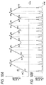
- Figs. 8A and 8B are drawings to illustrate the operation of the control circuit 101 in the present embodiment.
- Fig. 8A is a drawing to show a time change of numerical data N output from the CPU 201 to the D/A converter 202-2. In other words, it shows a time change of the passing wavelength of the wavelength-variable filter 105.
- A1 to A5 represent points where the transmission wavelength of the self station is detected and B1 to B5 points where the transmission wavelength of the other station is detected.
- Fig. 8B is a drawing to show a time change of numerical data M output from the A/D converter 203 to the CPU 201. The time scale of the abscissa corresponds to that of Fig. 8A.
- the transmitter 402 is connected through the optical dividing / power multiplexing element 401 to the transmission line.
- the setup of the wavelength control system enclosed in the transmitter 402 is shown in Fig. 3.
- the control circuit 101 controls the wavelength (i.e., the transmission wavelength) of the output light from the wavelength-variable light source 103 and the passing wavelength of the wavelength-variable filter 105 in the following manner.
- the control circuit 101 first sets the transmission wavelength ⁇ k and further sets the passing wavelength ⁇ f1 of the wavelength-variable filter 105 on the shorter wavelength side than ⁇ k. Then it sweeps the passing wavelength to the longer wavelength side, so that it then detects the transmission wavelength ⁇ k of the self station and the transmission wavelength ⁇ k-1 of the other station adjacent thereto on the longer wavelength side. This operation yields the wavelength spacing ⁇ c between the two wavelengths. Further, the control circuit 101 controls the transmission wavelength of the self station so that ⁇ c may be equal to the predetermined value ⁇ c0. After that, the control circuit repeats the operation of setting the sweep start wavelength, sweeping the passing wavelength to obtain ⁇ c, and controlling the transmission wavelength ⁇ k of the self station.
- the wavelength spacing ⁇ c converges to ⁇ c0.
- a state in which the wavelength spacing is converged at the predetermined spacing ⁇ c0 will be called as a steady state, and a state before reaching it as a non-steady state. It is, however, noted that the predetermined spacing cannot be precisely one value even in the steady state, but it has the permissible width.
- Figs. 7A to 7D show states of the control.
- the control circuit 101 starts the sweep from the wavelength ⁇ f1 shifted by ⁇ a from ⁇ k on the shorter wavelength side and monitors the intensity of transmitted light as sweeping the passing wavelength of the filter to the longer wavelength side.
- a first peak is obtained at the transmission wavelength ⁇ k of the self station, and a second peak at the transmission wavelength ⁇ k-1 of the other station.
- the control circuit 101 finishes the sweep of the passing wavelength at the wavelength ⁇ f2 shifted by ⁇ b from ⁇ k-1 on the longer wavelength side.
- This sweep from ⁇ f1 to ⁇ f2 is one sweep step.
- ⁇ a is a margin for surely detecting the transmission wavelength of the self station and ⁇ b similarly a margin for surely detecting the transmission wavelength of the other station.
- ⁇ c can approach ⁇ c0 most quickly.
- ⁇ d and ⁇ d' are set to
- a suitable arrangement is such that a proper fixed value ⁇ d0 is determined and the transmission wavelength ⁇ k of the self station is changed by ⁇ d0, if
- the transmission wavelength ⁇ k is set so as not to cause interference with transmission wavelengths under communication, which have already been sent to the transmission line. This can be realized for example by setting a transmission start region in a region on the shortest wavelength side in the wavelength range handled by itself.
- transmission is started in the transmission start region, and if the steady state is achieved in the transmission start region the transmission is interrupted.
- the transmission start region may be properly set to a region including approximately the predetermined spacing as described above or including an error of the wavelength-variable filter if it cannot be ignored.
- the entire wavelength range is arranged as a transmissible region without setting a specific transmission start region, it is first checked whether transmission light of other stations is present or absent near the transmission start wavelength prior to transmission start, and then transmission is started only when a necessary wavelength region is secured. Specifically, supposing that all transmission start wavelengths of respective stations are over a wavelength ⁇ limit and that errors of the wavelength-variable filters in the transmitters of respective stations (differences between actual wavelengths and transmission wavelengths expected for the transmitters) are below ⁇ error, the wavelength-variable filter is swept upon transmission start at least from the shorter wavelength side than ⁇ limit to ⁇ limit + ⁇ error + ⁇ c0 , and, without detection of a transmission wavelength of any other station, transmission is started as judging that the wavelength range not to cause interference upon transmission start can be secured.
- interference occurs if a transmission wavelength of one other station exists near the transmission start wavelength upon transmission start. Even with interference, because the transmission wavelength of the station which started transmission later is controlled so as to keep the predetermined spacing relative to the adjacent transmission wavelength in accordance with the above-described control, the transmission of the station having started the transmission later is quickly interrupted.
- transmission data in the interfered communication is data which permits abnormal receiving of partial data (for example, data permitting partial lack like dynamic picture data) the former transmission is continued without interruption; if the data does not permit abnormal receiving of partial data, a receiving station requests retransmission.
- a transmission start method may be selected depending upon the wavelength region handled, the predetermined spacing ⁇ c0, data transmitted, etc. from the above methods upon transmission start.
- the control circuit 101 changes the transmission wavelength of the self station to the longest wavelength side and stops there. Specifically, it holds an output from the drive circuit 102-1 for driving the wavelength-variable light source 103 at the output corresponding to the longest wavelength side.
- the control circuit 101 sets the transmission wavelength ⁇ k of the self station by outputting a suitable voltage to the drive circuit 102-1.
- the voltage corresponds to the numerical data output from the CPU 201 to the D/A converter 202-1.
- the control circuit 101 always sweeps the passing wavelength of the wavelength-variable filter 105 in order to obtain the wavelength spacing ⁇ c between the transmission wavelength ⁇ k of the self station and the transmission wavelength ⁇ k-1 of the other station.
- the CPU 201 sends the numerical data N to the D/A converter 202-2 and increases a value thereof by ⁇ n every short period ⁇ t.
- the a numerical value sent to the D/A converter 202-2 corresponds to the passing wavelength of the wavelength-variable filter 105, and ⁇ n to the smallest change of the passing wavelength of the wavelength-variable filter 105.
- the CPU 201 monitors the numerical value M output from the A/D converter 203.
- the numerical value M corresponds to the intensity of the light transmitted by the wavelength-variable filter 105.
- the CPU 201 increases the numerical data N sent to the D/A converter 202-2 (Fig. 8A), the numerical value M output from the A/D converter 203 comes to have a peak at a transmission wavelength of each station (Fig. 8B).
- the first peak (numerical value NA1) at point A1 corresponds to the transmission wavelength ⁇ k of the self station, and the second peak (numerical value NB1) at point B1 to the transmission wavelength ⁇ k-1 of the other station.
- the CPU 201 again sets the transmission wavelength ⁇ k of the self station and the sweep start wavelength ⁇ f1, based on a result of the comparison.
- the wavelength control as described forms an array of transmission wavelengths from the respective stations with the head on the longer wavelength side on the wavelength axis in the transmission line. After a certain station ends transmission, a gap appears in the array of transmission wavelengths thus arranged. On that occasion, an array of transmission wavelengths located on the shorter wavelength side than the gap move to the longer wavelength side so as to bridge the gap, whereby the wavelength region can be effectively used.
- the terminal station 303-k transmitting its signal with the wavelength ⁇ k stops transmission. Since the transmission wavelength ⁇ k is now absent in the transmission line, the terminal station 303-k + 1 comes not to detect any transmission signal from the other stations. Accordingly, the control circuit 101 in the terminal station 303-k + 1 changes the transmission wavelength ⁇ k + 1 of the self station to the longer wavelength side before it detects a transmission signal of another station.
- the terminal stations transmission their signals using the respective wavelengths on the shorter wavelength side than the terminal station 303-k + 1 control their own transmission wavelengths so that each station may keep constant a wavelength difference between the transmission wavelength of the self station and the transmission wavelength of the other station one wavelength adjacent thereto on the longer wavelength side. Therefore, the transmission wavelengths of those terminal stations move to the longer wavelength side as following up the transmission wavelength of the terminal station 303-k + 1, thereby finally filling the gap.
- the light coming from the transmission line advances through the optical dividing / power multiplexing element 401 to reach the receiver 403.
- the receiver receives only a light signal of the transmission wavelength ⁇ k of a terminal station intended to receive and then converts it into an electric signal to output it to the terminal equipment.
- the receiver 403 always checks whether there exists a signal newly sent to the transmission line or not. This will be called as a receiving standby state. Any terminal station not transmitting or receiving a signal is in the receiving standby state. A terminal station in the receiving standby state sets the receiving wavelength thereof on the longer wavelength side than the transmission start wavelengths of the respective stations to wait for a transmission signal from one other station. If there is a signal newly sent, the terminal station in the standby state determines whether it is a signal directed to the self station. If the signal is directed to the self station, it receives the signal; if not, the terminal station continues checking presence or absence of the signal.
- While a certain receiver 403 is receiving, for example, the transmission wavelength ⁇ k from the terminal station 303-1 and when the terminal station 303-1 moves the transmission wavelength ⁇ k in order to avoid interference or in order to keep the wavelength spacing at the predetermined spacing, the receiver 403 also moves the receiving wavelength in accordance therewith.
- This can be realized for example by applying the control method for making the passing wavelength of the wavelength-variable filter coincident with the transmission wavelength in the transmitter, as described previously, to the wavelength-variable filter in the receiver.
- a transmitting station can continue transmission as avoiding interference and a receiving station can continue receiving without being out of tuning. Since the transmission wavelengths of the respective stations are arranged at suitable intervals on the wavelength axis in the transmission line, the wavelength multiplicity can be increased. Further, it is not necessary to achieve precise stability of the transmission wavelength of each station.
- the present embodiment has the same configuration as the first embodiment, but is different in the method for controlling the wavelength-variable light source and the wavelength-variable filter in the transmitter. Specifically, return sweep is also utilized as one sweep step upon obtaining the wavelength spacing ⁇ c between the transmission wavelength of the self station and the transmission wavelength of the other station.
- FIG. 5 The schematic drawing of a system for achieving the wavelength-multiplexing optical communication method of the present embodiment is shown in Fig. 5, the schematic drawing of the optical transmitter-receiver portion in each station in Fig. 6, the setup of the transmitter in Fig. 3, and the setup of the control circuit in the transmitter in Fig. 4. Since the elements in the respective portions are the same as those in the first embodiment, description thereof is omitted herein.
- Figs. 10A, 10B are drawings to illustrate the operation of the control circuit 101 in the present embodiment.
- Fig. 10A is a drawing to show a time change of the numerical data N output from the CPU 201 to the D/A converter 202-2. In other words, it shows a time change of the wavelength transmitted by the wavelength-variable filter 105.
- A1 to A10 are points where the transmission wavelength of the self station is detected, and B1 to B10 points where the transmission wavelength of the other station is detected.
- Fig. 8B is a drawing to show a time change of the numerical data M output from the A/D converter 203 to the CPU 201.
- the time scale of the abscissa corresponds to that of Fig. 10A.
- control circuit 101 controls the wavelength (or the transmission wavelength) of the output light and the passing wavelength of the wavelength-variable filter 105.
- the passing wavelength of the wavelength-variable filter 105 is swept back to the shorter wavelength side from ⁇ f2 to ⁇ f1 thus updated, thereby detecting ⁇ k-1, ⁇ k in order and then obtaining the wavelength spacing ⁇ c.
- the control circuit 101 again controls the transmission wavelength of the self station so that ⁇ c may become equal to ⁇ c0. After that, the control circuit repeats the operation of obtaining the wavelength spacing ⁇ c as alternately changing the sweep direction of the passing wavelength every sweep step and controlling the transmission wavelength ⁇ k of the self station.
- the wavelength spacing ⁇ c comes to converge to ⁇ c0.
- ⁇ c can approach ⁇ c0 most quickly. If it is not suitable, a possible arrangement is such that a suitable fixed value ⁇ d0 is selected and that the transmission wavelength of the self station ⁇ k is changed by ⁇ d0, if
- the wavelength spacing ⁇ c can come to converge to ⁇ c0 faster than in the first embodiment.
- the numerical data output from the CPU 201 to the D/A converter 202-1 corresponds to the transmission wavelength ⁇ k of the self station.
- the numerical data N sent from the CPU 201 to the D/A converter 202-2 corresponds to the passing wavelength of the wavelength-variable filter 105, and sweep of the passing wavelength is effected by increasing or decreasing the value of the numerical data by ⁇ n every very short period ⁇ t.
- the numerical value M output from the A/D converter 203 corresponds to the intensity of the light transmitted by the wavelength-variable filter 105.
- the CPU 201 increases the numerical data N sent to the D/A converter 202-2 (Fig. 10A), the numerical value M output from the A/D converter 203 comes to have a peak at a transmission wavelength of each station (Fig. 10B). For example, suppose that a peak corresponding to the transmission wavelength ⁇ k of the self station appears at the numerical value NA1 and a peak corresponding to the transmission wavelength ⁇ k-1 of the other station at the numerical value NB1.
- the CPU 201 shifts the transmission wavelength of the self station ⁇ k by ⁇ d to the longer wavelength side. Namely, the CPU increases the numerical data sent to the D/A converter 202-1 by a value corresponding to ⁇ d (from A1 to A2 and from A2 to A3), and continues sweeping.
- the CPU 201 maintains the same setting as upon the previous sweep (from A5 to A6, from A6 to A7, from A8 to A9, and from A9 to A10), and again executes sweeping.
- the CPU 201 shifts the transmission wavelength of the self station ⁇ k by ⁇ d' to the shorter wavelength side. Namely, the CPU decreases the numerical data sent to the D/A converter 202-1 by a value corresponding to ⁇ d' (from A7 to A8), and continues sweeping.
- the wavelength control as described above forms an array of transmission wavelengths from the respective stations with the head on the longer wavelength side in the order of starts of communication on the wavelength axis in the transmission line, similarly as in the first embodiment. Further, with end of transmission of a certain terminal station, a gap appearing in the array of transmission wavelengths is also automatically bridged in the same manner as in the first embodiment.
- the setting method of the transmission wavelength ⁇ k upon transmission start, the control method when the transmission wavelength of the self station reaches the longest wavelength side of the wavelength range handled by itself, and the operation upon receiving are based on those in the first embodiment.
- the transmitting station can continue transmitting signals as avoiding interference, and the receiving station can continue receiving signals without being out of tuning. Since the transmission wavelengths of the respective stations are arranged at suitable intervals on the wavelength axis in the transmission line, the wavelength multiplicity can be increased. Further, precise stabilization is not necessary for the transmission wavelength of each station. Since the present embodiment also utilizes the return sweep as one sweep step, the wavelength spacing can be converged faster without quickly changing the passing wavelength of the wavelength-variable filter, as compared with Embodiment 1, and the margin for surely detecting the transmission wavelength of the self station can be set to 0 or to be very small.
- the present embodiment has the same configuration as the first embodiment, but is different from the first and second embodiments in the control method of the wavelength-variable light source and the wavelength-variable filter in the transmitter.
- Embodiments 1, 2 were arranged to detect the two wavelengths, i.e. the transmission wavelength of the self station and an adjacent transmission wavelength, in one sweep step even in the non-steady state, whereas Embodiments 3 and 4 to follow are arranged to detect only one wavelength in one sweep step before approach of the steady state.
- the present embodiment is so arranged that, in order to obtain the wavelength spacing ⁇ c between the transmission wavelength of the self station and the transmission wavelength of the other station, the passing wavelength of the wavelength-variable filter is repeatedly swept in a longer wavelength region in the proximity wavelength region to the transmission wavelength of the self station.
- FIG. 5 The schematic drawing of a system for achieving the wavelength-multiplexing optical communication system of the present embodiment is shown in Fig. 5, the schematic drawing of the optical transmitter-receiver portion of each station in Fig. 6, the setup of the transmitter in Fig. 3, and the setup of the control circuit in the transmitter in Fig. 4. Since the elements in the respective portions are the same as those in the first embodiment, the description thereof is omitted herein.
- Figs. 11A to 11D are drawings to show relations on the wavelength axis between the communicating wavelengths and the passing wavelength of the wavelength filter where a plurality of terminal stations are in communication by the present method.
- ⁇ 1 to ⁇ k-1 represent the transmission wavelengths of other stations, ⁇ k the transmission wavelength of the self station, ⁇ f1 the sweep start wavelength of the wavelength-variable filter 105 of the self station, ⁇ f2 the sweep return wavelength thereof, and ⁇ a a margin for surely detecting the transmission wavelength of the self station.
- ⁇ e is the width of sweep for surely detecting the transmission wavelength of the other station without causing interference with the transmission wavelength of the self station.
- ⁇ c represents the wavelength spacing between ⁇ k and ⁇ k-1, and ⁇ d, ⁇ d' moving amounts of ⁇ k, ⁇ f1 and ⁇ f2.
- Figs. 11A and 11B show cases where ⁇ c is greater than the predetermined value, Fig. 11C a case where ⁇ c is equal to the predetermined value, and Fig. 11D a case where ⁇ c is smaller than the predetermined value.
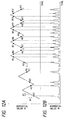
- Figs. 12A and 12B are drawings to illustrate the operation of the control circuit 101 in the present embodiment.
- Fig. 12A is a drawing to show a time change of the numerical data N output from the CPU 201 to the D/A converter 202-2. In other words, it shows a time change of the passing wavelength of the wavelength-variable filter 105.
- A1 to A12 represent points where the transmission wavelength of the self station is detected, and B5 to B12 points where the transmission wavelength of the other station is detected.
- Fig. 12B is a drawing to show a time change of the numerical data M output from the A/D converter 203. The time scale of the abscissa corresponds to that of Fig. 12A.
- the control circuit 101 Upon sending signals, in order to avoid interference and to effectively use the wavelengths, the control circuit 101 repeats the following operation.
- the control circuit first sets the transmission wavelength ⁇ k and then sets the passing wavelength of the wavelength-variable filter 105 on the shorter wavelength side than ⁇ k.
- the control circuit 101 sweeps the passing wavelength to the longer wavelength side as checking presence or absence of a transmission wavelength. Sweep is continued after detecting the transmission wavelength ⁇ k of the self station and turns back to the shorter wavelength side at a suitable wavelength. Then the control circuit continues sweeping to the shorter wavelength side as checking presence or absence of a transmission wavelength. Once it detects the transmission wavelength of the self station ⁇ k, sweep again turns back to the longer wavelength side.
- Figs. 11A to 11D show the details of the control.
- the control circuit 101 starts sweeping from the wavelength ⁇ f1 shifted by ⁇ a on the shorter wavelength side than ⁇ k and monitors the intensity of transmitted light as sweeping the passing wavelength of the filter to the longer wavelength side. A peak appears at the transmission wavelength of the self station ⁇ k, and the control circuit 101 continues sweeping up to the wavelength ⁇ f2 shifted by ⁇ e on the longer wavelength side from ⁇ k. Then the control circuit reverses the direction of sweep to the shorter wavelength side, and, detecting another peak of the transmission wavelength of the self station ⁇ k, it continues sweeping up to the wavelength ⁇ f1' shifted by ⁇ a on the shorter wavelength side from ⁇ k.
- the control circuit 101 shifts the transmission wavelength of the self station ⁇ k by ⁇ d to the longer wavelength side.
- the transmission wavelength of the self station ⁇ k, the sweep start wavelength ⁇ f1, and the sweep turning wavelength ⁇ f2 each increase by ⁇ d.
- control circuit 101 If the control circuit detects the transmission wavelength of the other station ⁇ k-1 and if the difference from the transmission wavelength of the self station ⁇ k'' is equal to the predetermined value ⁇ c0 (Fig. 11C), the, control circuit 101 maintains the value of ⁇ k''.
- control circuit 101 If the control circuit detects the transmission wavelength of the other station ⁇ k-1 and if the difference ⁇ c'' between the transmission wavelength of the self station ⁇ k''' and the transmission wavelength of the other station ⁇ k-1 is smaller than the predetermined value ⁇ c0, the control circuit 101 shifts the transmission wavelength of the self station by ⁇ d' to the shorter wavelength side.
- control circuit 101 sweeps back the passing wavelength of the wavelength-variable filter 105 to the shorter wavelength side to detect ⁇ k-1, ⁇ k in order, thereby obtaining the wavelength spacing ⁇ c. Then the control circuit 101 again controls the transmission wavelength of the self station so that ⁇ c may become equal to ⁇ c0.
- control circuit repeats such operation as to obtain the wavelength spacing ⁇ c as alternately changing the sweep direction of the passing wavelength and then to control the transmission wavelength ⁇ k of the self station.
- the wavelength spacing ⁇ c comes to converge to ⁇ c0.
- the spacing ⁇ c can approach ⁇ c0 most quickly by setting the value of ⁇ d to ⁇ e if the control circuit 101 does not detect the transmission wavelength of the other station ⁇ k-1 or to
- the numerical data output from the CPU 201 to the D/A converter 202-1 corresponds to the transmission wavelength ⁇ k of the self station.
- the numerical data N sent from the CPU 201 to the D/A converter 202-2 corresponds to the passing wavelength of the wavelength-variable filter 105, and sweep of the passing wavelength is carried out by increasing or decreasing the value by ⁇ n every very short period ⁇ t.
- the numerical value M output from the A/D converter 203 corresponds to the intensity of the light transmitted by the wavelength-variable filter 105.
- the CPU 201 increases or decreases the numerical data N sent to the D/A converter 202-2 (Fig. 12A), the numerical value M output from the A/D converter 203 comes to have peaks corresponding to the transmission wavelengths of the respective stations (Fig. 12B).
- the CPU 201 sweeps regions near the peaks (point A1 to point A12) corresponding to the transmission wavelength ⁇ k of the self station within a certain sweep width (corresponding to ⁇ a + ⁇ e in Figs. 11A to 11D) in order to find the peaks (point B5 to point B12) corresponding to the transmission wavelength ⁇ k-1 of the other station.
- the CPU 201 shifts the transmission wavelength of the self station ⁇ k by ⁇ d to the longer wavelength side. Namely, the CPU increases the numerical data N sent to the D/A converter 202-1 by the value corresponding to ⁇ d (from A1 to A2, from A2 to A3, and from A3 to A4), and thus continues sweeping.
- the CPU 201 shifts ⁇ k by ⁇ d to the longer wavelength side. Namely, the CPU increases the numerical data sent to the D/A converter 202-1 by the value corresponding to ⁇ d (from A5 to A6), and then continues sweeping.
- the CPU 201 maintains the same setting as upon previous sweep (from A6 to A7, from A7 to A8, from A8 to A9, from A10 to A11, and from A11 to A12), and again performs sweeping.
- the CPU 201 shifts the transmission wavelength of the self station ⁇ k by ⁇ d' to the shorter wavelength side. Namely, the CPU decreases the numerical data sent to the D/A converter 202-1 by the value corresponding to ⁇ d' (from A9 to A10), and then continues sweeping.
- the wavelength control as described above forms an array of the transmission wavelengths from the respective stations with the head on the longer wavelength side in order of communication start on the wavelength axis in the transmission line, similarly as in the first embodiment. Further, with transmission end of a certain terminal station, a gap appearing in the array of transmission wavelengths is automatically bridged, which is also the same.
- the setting method of the transmission wavelength ⁇ k upon transmission start, the control method when the transmission wavelength of the self station reaches the longest wavelength side of the wavelength range handled by itself, and the operation upon receiving signals are also based on those in the first embodiment.
- a transmitting station can continue transmission as avoiding interference and a receiving station can continue receiving without being out of tuning. Since the transmission wavelengths of the respective stations are arranged at suitable intervals on the wavelength axis in the transmission line, the wavelength multiplicity can be increased. Further, it is not necessary to achieve precise stability of the transmission wavelength of each station.
- the present embodiment is arranged to detect only one wavelength in one sweep step before approach of the steady state, similarly as in Embodiment 3.
- the present embodiment is different from Embodiment 3 in that, in order to obtain the wavelength spacing ⁇ c between the transmission wavelength of the self station and the transmission wavelength of the other station, the passing wavelength of the wavelength-variable filter is repeatedly swept in a shorter-wavelength-side region in the proximity wavelength region to the transmission wavelength of the other station adjacent to the transmission wavelength of the self station on the longer wavelength side.
- FIG. 5 The schematic drawing of a system for achieving the wavelength-multiplexing optical communication method of the present embodiment is shown in Fig. 5, the schematic drawing of the optical transmitter-receiver portion of each station in Fig. 6, the setup of the transmitter in Fig. 3, and the setup of the control circuit in the transmitter in Fig. 4. Since the elements in the respective portions are the same as those in the first embodiment, the description thereof is omitted herein.
- Figs. 13A to 13D are drawings to show relations on the wavelength axis between the communicating wavelengths and the passing wavelength of the wavelength-variable filter where there are a plurality of terminal stations communicating by the present method.
- ⁇ 1 to ⁇ k-1 represent transmission wavelengths of other stations, ⁇ k the transmission wavelength of the self station, ⁇ f1 the sweep start wavelength of the wavelength-variable filter 105 of the self station, ⁇ f2 the sweep turning wavelength thereof, and ⁇ a a margin for surely detecting the transmission wavelength of the self station ⁇ k before the transmission wavelength ⁇ k of the self station comes to interfere with the transmission wavelength ⁇ k-1 of the other station.
- ⁇ b is a margin for surely detecting the transmission wavelength of the other station ⁇ k-1.
- ⁇ c is the wavelength spacing between ⁇ k and ⁇ k-1.
- ⁇ d, ⁇ d' represent moving amounts of ⁇ k, ⁇ f1, and ⁇ f2.
- Figs. 13A and 13B show cases where ⁇ c is greater than the predetermined value, Fig. 13C a case where ⁇ c is equal to the predetermined value, and Fig. 13D a case where ⁇ c is smaller than the predetermined value.
- Figs. 14A and 14B are drawings to illustrate the operation of the control circuit 101 in the present embodiment.
- Fig. 14A is a drawing to show a time change of the numerical data N output from the CPU 201 to the D/A converter 202-2.
- Fig. 14A shows a time change of the passing wavelength of the wavelength-variable filter 105.
- A1, A3 to A10 represent points where the transmission wavelength of the self station is detected, and B1 to B10 points where the transmission wavelength of the other station is detected.
- Fig. 14B is a drawing to show a time change of the numerical data M output from the A/D converter 203.
- the time scale of the abscissa corresponds to that of Fig. 14A.
- control circuit 101 Upon transmission, in order to avoid interference and to effectively use the wavelengths, the control circuit 101 repeats the following operation.
- the control circuit first sets the transmission wavelength ⁇ k and then sets the passing wavelength of the wavelength-variable filter 105 on the shorter wavelength side than ⁇ k.
- the control circuit 101 then sweeps the passing wavelength to the longer wavelength side as checking presence or absence of a transmission wavelength, thereby detecting the transmission wavelength of the self station ⁇ k and the transmission wavelength ⁇ k-1 of the other station adjacent thereto on the longer wavelength side.
- control circuit 101 turns the passing wavelength of the wavelength-variable filter 105 back to the shorter wavelength side, and then continues sweeping as checking presence or absence of a transmission wavelength. After detecting the transmission wavelength of the other station ⁇ k-1, the control circuit continues sweeping and then turns sweep back to the longer wavelength side at an appropriate wavelength. Then it continues sweeping as checking presence or absence of a transmission wavelength, and, once detecting the transmission wavelength ⁇ k-1 of the other station, it again turns sweep back to the longer wavelength side.
- This is carried out for the purpose of checking presence or absence of the transmission wavelength of the self station and a change thereof in the proximity wavelength region on the shorter wavelength side of the transmission wavelength of the other station ⁇ k-1. If the control circuit 101 does not detect the transmission wavelength of the self station ⁇ k it changes the transmission wavelength of the self station ⁇ k to the longer wavelength side; if it detects ⁇ k it controls the transmission wavelength of the self station ⁇ k so that the wavelength spacing ⁇ c ⁇ k-1 - ⁇ k between the two wavelengths may become equal to the predetermined value ⁇ c0.
- Figs. 13A to 13D show the details of the control.
- the control circuit 101 starts sweeping from the wavelength ⁇ f1 shifted by ⁇ a to the shorter wavelength side from ⁇ k, and monitors the intensity of the transmitted light as sweeping the passing wavelength of the filter to the longer wavelength side. A peak appears at a transmission wavelength of each station.
- the control circuit 101 first detects the transmission wavelength ⁇ k of the self station and the transmission wavelength ⁇ k-1 of the other station adjacent thereto on the longer wavelength side. After detecting ⁇ k-1, the control circuit 101 continues sweeping from ⁇ k-1 up to the wavelength ⁇ f2 shifted by ⁇ b on the longer wavelength side.
- control circuit 101 reverses the direction of sweep to the shorter wavelength side, and, once detecting a peak of the transmission wavelength of the other station ⁇ k-1, it continues sweeping from ⁇ k-1 to the wavelength ⁇ f1' shifted by ⁇ a + ⁇ c0 on the shorter wavelength side.
- control circuit 101 shifts the transmission wavelength of the self station ⁇ k by ⁇ d to the longer wavelength side.
- control circuit 101 If the control circuit detects the transmission wavelength of the self station ⁇ k'' and if the difference from ⁇ k-1 is equal to ⁇ c0 (Fig. 13C), the control circuit 101 maintains the value of ⁇ k''.
- control circuit 101 shifts the transmission wavelength of the self station by ⁇ d' to the shorter wavelength side.
- the passing wavelength of the wavelength-variable filter 105 is swept back to the longer wavelength side to detect ⁇ k, ⁇ k-1 in order, thereby obtaining the wavelength spacing ⁇ c.
- the control circuit 101 again controls the transmission wavelength of the self station so that ⁇ c may become equal to ⁇ c0.
- control circuit repeats such operation as to sweep the passing wavelength in the proximity wavelength region of ⁇ k-1, obtain the wavelength spacing ⁇ c, and then control the transmission wavelength ⁇ k of the self station, as alternately changing the direction of sweep.
- the wavelength spacing ⁇ c comes to converge to ⁇ c0.
- ⁇ c can approach ⁇ c0 most quickly. If it is not suitable, a possible arrangement may be constructed in such a manner that a proper fixed value ⁇ d0 is selected and the transmission wavelength of the self station ⁇ k is changed by ⁇ d0, if
- the numerical data output from the CPU 201 to the D/A converter 202-1 corresponds to the transmission wavelength ⁇ k of the self station.
- the numerical data N sent from the CPU 201 to the D/A converter 202-2 corresponds to the passing wavelength of the wavelength-variable filter 105, and sweep of the passing wavelength is carried out by increasing or decreasing the value by ⁇ n every very short period ⁇ t.
- the numerical value M output from the A/D converter 203 corresponds to the intensity of the light transmitted by the wavelength-variable filter 105.
- the CPU 201 increases or decreases the numerical data N sent to the D/A converter 202-2 (Fig. 14A), the numerical value M output from the A/D converter 203 comes to have a peak corresponding to the transmission wavelength of each station (Fig. 14B).
- the CPU 201 repeatedly sweeps the vicinity of a peak (point B1 to point B10) corresponding to the transmission wavelength of the other station ⁇ k-1 with a certain sweep width (corresponding to ⁇ a + ⁇ b + ⁇ c0 in Figs. 13A-13B) to look for a peak corresponding to the transmission wavelength of the self station ⁇ k.
- the CPU 201 shifts the transmission wavelength of the self station ⁇ k by ⁇ d to the longer wavelength side. Namely, the CPU increases the numerical data N sent to the D/A converter 202-1 by the value corresponding to ⁇ d, and continues sweeping.
- the CPU 201 executes the following processing. For example, suppose that a peak corresponding to ⁇ k appears when the numerical value sent to the D/A converter 202-2 is NA and a peak corresponding to ⁇ k-1 appears when the numerical value is NB.
- the CPU 201 shifts ⁇ k by ⁇ d to the longer wavelength side. Namely, it increases the numerical data N sent to the D/A converter 202-1 by the value corresponding to ⁇ d (from A3 to A4), and continues sweeping.
- the CPU 201 maintains the same setting as upon the previous sweep (from A5 to A6, from A8 to A9, and from A9 to A10), and again performs sweeping.
- the CPU 201 shifts the transmission wavelength of the self station ⁇ k by ⁇ d' to the shorter wavelength side. Namely, it decreases the numerical data N sent to the D/A converter 202-1 by the value corresponding to ⁇ d' (from A7 to A8), and continues sweeping.
- the wavelength control as described above forms an array of the transmission wavelengths from the respective stations with the head on the longer wavelength side in order of communication starts on the wavelength axis in the transmission line, similarly as in the first embodiment. Further, with transmission end of a certain terminal station, a gap appearing in the array of transmission wavelengths is automatically bridged in the same manner as in the first embodiment.
- the setting method of the transmission wavelength ⁇ k upon transmission start, the control method when the transmission wavelength of the self station reaches the longest wavelength side of the wavelength range handled by itself, and the operation upon receiving are based on those in the first embodiment.
- a transmitting station can continue sending signals as avoiding interference, and a receiving station can continue receiving signals without being out of tuning. Since the transmission wavelengths of the respective stations are arranged at suitable intervals on the wavelength axis in the transmission line, the wavelength multiplicity can be increased. Further, it is not necessary to achieve precise stability of the transmission wavelength of each station.
- Embodiment 3 Since the present embodiment, as well as Embodiment 3, is arranged to detect only either one of the transmission wavelength of the self station and the adjacent transmission wavelength before reaching the steady state, one sweep step is short. In the previous embodiments and the present embodiment, the transmission wavelength is moved properly for each sweep step.
- the time for convergence to the steady state can be made shorter in Embodiments 3 and 4 because one sweep step in Embodiments 3 and 4 is short.
- the present embodiment is different from Embodiments 1 to 4 as described above in that each station has two wavelength-variable filters for wavelength control.
- the present embodiment employs an analog circuit as the control circuit, and performs feedback control by the wobbling method.
- Fig. 15 is a structural drawing of a wavelength control system in the transmitter of the present embodiment.
- Reference numeral 1303 designates a control circuit, which controls an output wavelength of a wavelength-variable light source 1303 and passing wavelengths of wavelength-variable filters 1307-1 and 1307-2 in order to avoid interference with another terminal station.
- Numeral 1302-1 denotes a drive circuit, which drives the wavelength-variable light source 1303, based on a signal from the control circuit 1301.
- Numeral 1303 is the wavelength-variable light source, which outputs light to an optical dividing element 1304. This light source can change the wavelength of the output light therefrom by control from the outside, for example like a semiconductor laser.
- the light source can also modulate, for example, the intensity of the output light in accordance with a transmission signal from the outside.
- Numeral 1304 denotes the optical dividing element, which divides the output light from the wavelength-variable light source 1303 into two beams and outputs them to the wavelength-variable filter 1307-1 and to an optical dividing / power multiplexing element 1308.
- Numerals 1307-1 and 1307-2 denote the wavelength-variable filters, which are filters that can change their wavelength regions of the transmitted light by external control, for example such as fiber Fabry-Perot filters.
- Numeral 1306-1 is a light receiving element, which receives the light from the wavelength-variable light source 1303, having been transmitted by the wavelength-variable filter 1307-1.
- Numeral 1305-1 denotes an amplifier, which amplifies a signal from the light receiving element 1306-1 and outputs it to the control circuit 1301.
- Numeral 1302-2 is a drive circuit, which drives the wavelength-variable filter 1307-1, based on a signal from the control circuit 1301.
- Numeral 1308 is the optical dividing / power multiplexing element, which outputs the output light from the optical dividing element 1304 to the transmission line and outputs received light from the transmission line to the wavelength-variable filter 1307-2.
- Numeral 1306-2 represents a light receiving element, which receives the light from the transmission line, having been transmitted by the wavelength-variable filter 1307-2.
- Numeral 1305-2 is an amplifier, which amplifies a signal from the light receiving element 1306-2 and outputs it to the control circuit 1301.
- Numeral 1302-3 is a drive circuit, which drives the wavelength-variable filter 1307-2, based on a signal from the control circuit 1301.
- each of the optical dividing element 1304 and the optical dividing / power multiplexing element 1308 is constructed for example of a half mirror or a beam splitter.
- the wavelength-variable light source 1303 may be the one as used in Embodiments 1 to 4.
- the wavelength-variable light source 1303 is also composed of the wavelength adjusting section for changing the wavelength of the output light and the output light modulating section for modulating the output light.
- the DBR portion corresponds to the wavelength adjusting section and the active region to the output light modulating section.
- the drive circuit 1302-1 is connected to the wavelength adjusting section. Further, a transmission signal from the terminal equipment is input into the output light modulating section.
- the present embodiment may also employ, for example, the FFP (fiber Fabry-Perot) type filters as the wavelength-variable filters 1307-1, 1307-2.
- FFP fiber Fabry-Perot
- the wavelength of the wavelength-variable light source 1303 and the passing wavelengths of the wavelength-variable filters 1307-1, 1307-2 each change to the longer wavelength side. Further, when a same voltage is applied to the drive circuits 1302-2 and 1302-3, the passing wavelengths of the wavelength-variable filters 1307-1 and 1307-2 coincide with each other. Namely, the drive circuits 1302-2 and 1302-3 are arranged to absorb the difference in sweep characteristics of the passing wavelengths between the wavelength-variable filters 1307-1 and 1307-2.
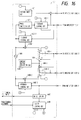
- Fig. 16 is a drawing to show the setup of the control circuit 1301 shown in Fig. 15.
- Numeral 1401 is a voltage sweep circuit, which outputs a control signal for determining the output wavelength of the wavelength-variable light source 1303 to the drive circuit 1302-1.
- Numeral 1402-1 is a feedback control circuit, which generates a control signal, based on a signal from the amplifier 1305-1 and a signal from the phase inversion circuit 1403, and outputs it to the drive circuit 1302-1.
- Numeral 1403 denotes a phase inversion circuit, which inverts the phase of the signal from the oscillator 1404 and outputs the inverted signal to feedback control circuit 1402-1.
- Numeral 1402-2 is a feedback control circuit, which generates a control signal, based on the signal from the amplifier 1305-1 and the signal from an oscillator 1404, and outputs it to a switch 1405-1.
- Numeral 1404 denotes the oscillator, which outputs a signal to the feedback control circuits 1402-2, 1402-3, phase inversion circuit 1403, and switches 1405-1, 1405-2.
- Numeral 1405-1 is a switch for switching two inputs, which outputs either one of a sum signal between the control signal from the feedback control circuit 1402-2 and the signal from the oscillator 1404 and a difference signal between the output signal from the switch 1405-2 and a signal from a constant voltage generation circuit 1406 to the drive circuit 1302-2 and to the switch 1405-2.
- Numeral 1406 is the constant voltage generation circuit, which generates a constant voltage and outputs it to the switches 1405-1 and 1405-2.
- Numeral 1405-2 is a switch for switching two inputs, which outputs either one of a sum signal between the control signal from the feedback control circuit 1402-3 and the signal from the oscillator 1404 and a sum signal between the output signal from the switch 1405-2 and the signal from the constant voltage generation circuit 1406 to the drive circuit 1302-3 and the switch 1405-1.
- Numeral 1402-3 denotes the feedback control circuit, which generates a control signal, based on the signal from the amplifier 1305-2 and the signal from the oscillator 1404 and outputs it to the switch 1405-2.
- Numeral 1407 designates a detection circuit, which determines upon transmission whether there exists a transmission wavelength of one other station in the proximity wavelength region of the transmission wavelength of the self station or not and outputs a signal indicating a result thereof to an ON/OFF control circuit 1408. Upon receiving, the detection circuit 1407 detects a receiving signal based on the signal from the amplifier 1305-2 and outputs it to the terminal equipment.
- Numeral 1408 is the ON/OFF control circuit, which controls ON/OFF of sweep of the voltage sweep circuit 1401, ON/OFF of feedback of the feedback control circuits 1402-1 to -3, and switch of inputs of the switches 1405-1, 1405-2.
- Numeral 1409-1 is an adder, which adds the output from the feedback control circuit 1402-2 to the output from the oscillator 1404 and outputs a result to the switch 1405-1.
- Numeral 1409-2 is also the adder, which adds an output from the feedback control circuit 1402-3 to the output from the oscillator 1404 and outputs a result to the switch 1405-2.
- Numeral 1409-3 is an adder, which adds the output from the switch 1405-1 to the output from the constant voltage generation circuit 1406 and outputs a result to the switch 1405-2.
- Numeral 1410 is a subtracter, which subtracts the output from the constant voltage generation circuit 1406 from the output from the switch 1405-2 and outputs a result to the switch 1405-1.
- a system for achieving the wavelength-multiplexing optical communication method of the present embodiment is the one shown in Fig. 5.
- the setup of the optical transmitter-receiver portion of each terminal 302-1 to 302-n is the same as the one shown in Fig. 6.
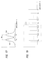
- Fig. 17 is a drawing to show a relative relation between the passing wavelengths of the wavelength-variable filters 1307-1, 1307-2 shown in Fig. 15 and the output wavelength of the wavelength-variable light source 1303.
- numeral 1501 indicates a wavelength transmission characteristic of the wavelength-variable filter 1307-1
- numeral 1502 a wavelength transmission characteristic of the wavelength-variable filter 1307-2.
- ⁇ k represents the transmission wavelength of the wavelength-variable light source 1303 and the passing wavelength of the wavelength-variable filter 1307-1
- ⁇ 1 the passing wavelength of the wavelength-variable filter 1307-2.
- Figs. 18A to 18C show relations on the wavelength axis between the communicating wavelengths and the passing wavelengths of the wavelength filters where there are a plurality of terminal stations communicating by the present method.
- ⁇ 1 to ⁇ k-1 represent transmission wavelengths of other terminals.
- ⁇ k and ⁇ k' are transmission wavelengths of the self terminal (say a terminal 303-1).
- Numeral 1601 represents a transmitting spectrum of the wavelength-variable filter 1307-1 of the self terminal.
- Numeral 1602 indicates a transmitting spectrum of the wavelength-variable filter 1307-2 of the self terminal.
- Fig. 18A shows a case where the self terminal starts transmission
- Fig. 18B a case where the self terminal detects a transmission wavelength of another terminal
- Fig. 18C a case where the transmission wavelength of the self terminal reaches the longest wavelength side of the wavelength range handled by itself.
- Fig. 19 is a drawing to illustrate a state of the control of communication wavelengths where there are a plurality of terminals communicating by the present method.
- ⁇ 1 to ⁇ m represent the transmission wavelengths of the respective terminals.
- Fig. 22 is a drawing to illustrate the operation of the ON/OFF control circuit 1408 in the control circuit 1301 in the present embodiment.
- the transmitter 402 is connected through the optical dividing / power multiplexing element 401 to the transmission line.
- the setup of the wavelength control system enclosed in the transmitter 402 is shown in Fig. 15.
- the control circuit 1301 controls the wavelength of the output light from the wavelength-variable light source 1303, i.e., the transmission wavelength, and the passing wavelengths of the wavelength-variable filters 1307-1, 1307-2 in the following manner.
- Fig. 17 shows the relative relation among the transmission wavelength and the two passing wavelengths of the wavelength-variable filters.
- Figs. 18A to 18C show relations on the wavelength axis between the transmission wavelengths and the passing wavelengths of the wavelength-variable filters for plural terminals in communication by the present method.
- Fig. 18A shows a case where a transmission signal of another terminal is not detected or where the intensity of the transmitted light by the wavelength-variable filter 1307-2 does not exceed a predetermined value.
- the control circuit 1301 controls the passing wavelength of the wavelength-variable filter 1307-1 so as to follow up the transmission wavelength.
- the control circuit controls the passing wavelength of the wavelength-variable filter 1307-2 so that it can follow up the passing wavelength of the wavelength-variable filter 1307-1 as keeping the wavelength difference ⁇ constant. Further, the control circuit continuously changes the transmission wavelength ⁇ k of the self terminal to the longer wavelength side.
- a method for starting transmission of the self terminal may be selected from those as described in Embodiment 1.
- the transmission wavelength of the self terminal reaches the longest wavelength side of the wavelength range handled by itself without detecting a transmission signal of any other terminal (Fig. 18C).
- a transmission signal of any other terminal Fig. 18C
- the control circuit 1301 stops changing the transmission wavelength to the further longer wavelength side.
- the control circuit holds the output from the drive circuit 1302-1 for driving the wavelength-variable light source 1303.
- Fig. 18B shows a case where a transmission signal of another terminal is detected, that is, where the intensity of the transmitted light by the wavelength-variable filter 1307-2 exceeds the predetermined value.
- the control circuit 1301 controls the passing wavelength of the wavelength-variable filter 1307-2 so as to make it coincide with the transmission wavelength ⁇ k-1 from another terminal.
- the control circuit controls the passing wavelength of the wavelength-variable filter 1307-1 so as to make it follow up the passing wavelength of the wavelength-variable filter 1307-2 as keeping the wavelength difference ⁇ constant.
- the control circuit controls the transmission wavelength ⁇ k' so as to make it coincide with the passing wavelength of the wavelength-variable filter 1307-1.
- This control forms an array of the transmission wavelengths from the respective terminals with the head on the longer wavelength side on the wavelength axis in the transmission line.
- Fig. 19 shows a state of the control.
- m terminals of 303-1 to 303-m are transmitting respective signals, using their own wavelengths of ⁇ 1 to ⁇ m.
- control circuit 1301 performing the wavelength control as described above.
- This control circuit is arranged to switch the control methods of wavelengths in accordance with determination of the ON/OFF control circuit, based on a signal from the terminal equipment or a signal from the detection circuit 1407, as discriminating the following two cases from each other: (1) a case where a transmission signal of another terminal is not detected; (2) a case where a transmission signal of another terminal is detected.
- Fig. 22 shows the control performed by the ON/OFF control circuit for the respective cases. The operation in the respective cases is explained in order.
- the control circuit 1301 controls the wavelength-variable light source 1303 to output a signal from the terminal equipment as gradually increasing the transmission wavelength.
- the voltage sweep circuit 1401 outputs to the drive circuit 1302-1 a signal to gradually increase the voltage as a wavelength control signal, thereby increasing the transmission wavelength of the wavelength-variable light source 1303.
- the feedback control circuit 1402-1 is not actuated.
- control circuit 1301 controls the passing wavelength of the wavelength-variable filter 1307-1 so as to make it coincide with the transmission wavelength of the wavelength-variable light source 1303.
- the feedback control circuit 1402-2 is actuated to generate a control signal for the wavelength-variable filter 1307-1, based on the signal from the amplifier 1305-1 (a light signal transmitted by the wavelength-variable filter 1307-1).
- the switch 1405-1 is on on the side A to output the control signal as described above to the drive circuit 1302-2, thereby controlling the passing wavelength of the wavelength-variable filter 1307-1.
- each feedback control circuit 1402-1 to 1402-3 is arranged to compare an input signal with a modulation signal from a modulator 204 for effecting fine modulation, and to output a control signal which is positive if the two signals have the same phase or negative if the signals have the opposite phases, as a control signal.
- a control signal which is positive if the two signals have the same phase or negative if the signals have the opposite phases.
- the passing wavelength of the wavelength-variable filter is also finely modulated.
- the passing wavelength can be made coincide with the transmission wavelength by feeding the above output back to the passing wavelength of the wavelength-variable filter.
- the principle and constitution of such feedback control circuit and filter control system are explained in detail for example in Japanese Laid-open Patent Application No. 1-177518.
- the wavelength control circuit 1301 controls the passing wavelength of the wavelength-variable filter 1307-2 to keep the difference ⁇ of the center passing wavelength from the wavelength-variable filter 1307-1 always constant.
- the feedback control circuit 1402-2 is actuated and the output therefrom is added to the output from the constant voltage generation circuit 1406 to generate a control signal for the wavelength-variable filter 1307-2.
- a voltage generated by the constant voltage generation circuit corresponds to a wavelength of the difference between the passing wavelengths of the two wavelength-variable filters.
- the switch 1405-2 is on on the side A, and the control signal as described above is output to the drive circuit 1302-3, thereby controlling the passing wavelength of the wavelength-variable filter 1307-2.
- the feedback control circuit 1402-3 is not actuated.
- the detection circuit 1407 is monitoring the signal from the amplifier 1305-2. When the signal exceeds a predetermined level, the detection circuit sends a control signal of "detected" to the ON/OFF control circuit 1408. This level is set lower than the level of the signal output from the amplifier 1305-2 when the transmission wavelength of the other terminal approaches the transmission wavelength of the self terminal up to immediately before causing interference.
- a special case conceivable is a case where the transmission wavelength of the self terminal is located on the longest wavelength side among the transmission wavelengths on the transmission line. This corresponds to the case of Fig. 18C.
- the output voltage of the voltage sweep circuit 1401 is arranged to saturate at a certain value. This value is set on the as longer wavelength side as possible in a common portion of the wavelength-variable ranges of the wavelength-variable light source and the two wavelength-variable filters.
- the control circuit 1301 controls the wavelength-variable light source 1303 to make the transmission-wavelength coincide with the passing wavelength of the wavelength-variable filter 1307-1. For that, the control circuit keeps the output from the voltage sweep circuit at the same magnitude as that at the time of change from the state of the case (1). Further, the feedback control circuit 1402-1 is actuated to generate a control signal for the wavelength-variable light source 1303, based on the signal from the amplifier 1305-2.
- the control circuit 1301 also controls the passing wavelength of the wavelength-variable filter 1307-1 to keep a wavelength difference from the passing wavelength of the wavelength-variable filter 1307-2 always constant. For that, the switches 1405-1 and 1405-2 are made on on the side B.
- the feedback control circuit 1402-3 is actuated, an output from the constant voltage generation circuit 1406 is subtracted from the output from the feedback control circuit, and thereafter the result is output to the drive circuit 1302-2 to change the passing wavelength of the wavelength-variable filter 1307-1.
- the feedback control circuit 1402-2 is not actuated.
- control circuit 1301 controls the passing wavelength of the wavelength-variable filter 1307-2 to make the passing wavelength coincide with a transmission wavelength of another terminal located on the longer wavelength side than and closest to the transmission wavelength of the self terminal out of the transmission wavelengths of the other terminals.
- This wavelength corresponds to ⁇ k-1 in Fig. 18B.
- the feedback control circuit 1402-3 is actuated to generate a control signal for the wavelength-variable filter 1307-2, based on the signal from the amplifier 1305-2 (the light signal transmitted by the wavelength-variable filter 1307-2).
- the switch 1405-2 is made on on the side B, and the control signal as described above is output to the drive circuit 1302-3, thereby controlling the passing wavelength of the wavelength-variable filter 1307-2.
- the detection circuit 1407 is monitoring the signal from the amplifier 1305-2, and sends a control signal of "not detected” to the ON/OFF control circuit 1408 when the signal becomes lower than the predetermined level.
- a transmitting terminal can continue transmitting signals as avoiding interference, and a receiving terminal can continue receiving signals without being out of tuning. Since the transmission wavelengths of the respective stations are arranged at suitable intervals on the wavelength axis in the transmission line, the wavelength multiplicity can be increased. Further, it is not necessary to achieve precise stability of the transmission wavelength of each station.
- the basic constitution and operation of the present embodiment are the same as those of Embodiment 5.
- the present embodiment realizes the control of the wavelength-variable light source and wavelength-variable filters in the transmitter by using a control circuit having a construction different from that in Embodiment 5.
- a digital circuit is used as the control circuit, and thus, feedback control is carried out by digital control.
- FIG. 5 The schematic drawing of a system for achieving the wavelength-multiplexing optical communication method of the present embodiment is shown in Fig. 5, and the schematic drawing of the optical transmitter-receiver portion of each terminal in Fig. 15. The operation of each portion is the same as in Embodiment 5, and thus, the description is omitted herein.
- Fig. 20 is a drawing to show the setup in the present embodiment, of the control circuit 1301 shown in Fig. 15.
- Numeral 1801 designates a CPU, which receives a control signal from terminal equipment, receives data from A/D converters 1803-1 and 1803-2, and sends data to D/A converters 1802-1 to 1802-3 after completion of necessary calculation.
- Numeral 1802-1 is a converter, which outputs a control signal for determining the transmission wavelength of the wavelength-variable light source 1303 to the drive circuit 1302-1, based on the data from the CPU 1801.
- Numeral 1802-2 is a D/A converter, which outputs a control signal for determining the passing wavelength of the wavelength-variable filter 1307-1 to the drive circuit 1302-2, based on the data from the CPU 1801.
- Numeral 1802-3 is a D/A converter, which outputs a control signal for determining the passing wavelength of the wavelength-variable filter 1307-2 to the drive circuit 1302-3, based on the data from the CPU 1801.
- Numeral 1803-1 is an A/D converter, which converts the signal obtained from the amplifier 1305-1 into a digital signal and outputs it to the CPU 1801.
- Numeral 1803-2 is an A/D converter, which converts the signal obtained from the amplifier 1305-2 into a digital signal and outputs it to the CPU 1801.
- Figs. 21A to 21C are drawings to illustrate the operation of the control circuit 1301 in the present embodiment.
- Fig. 21A shows a time change of transmission spectrum of the wavelength-variable filter
- Fig. 21B a time change of a numerical value sent from the control circuit to the D/A converter
- Fig. 21C a time change of a numerical value received by the control circuit from the A/D converter.
- control circuit 1301 in the present embodiment, having the above arrangement. Also in this control circuit, the operation is different between the following two cases: (1) the case where a transmission signal of another terminal is not detected; (2) the case where a transmission signal of another terminal is detected.
- the operation states are switched by the CPU 1801, judging either based on the signal from the terminal equipment and the signal from the A/D converter 1803-2. The two cases will be explained in order.
- the control circuit 1301 controls the wavelength-variable light source 1303 to output the signal from the terminal equipment to the transmission line as gradually increasing the transmission wavelength.
- the CPU 1801 controls the D/A converter 1802-1 to gradually increase the output therefrom.
- the output from the D/A converter 1802-1 is sent to the drive circuit 1302-1 to increase the wavelength of the output light from the wavelength-variable light source 1303.
- the control circuit 1301 controls the passing wavelength of the wavelength-variable filter 1307-1 to make it coincide with the transmission wavelength of the wavelength-variable light source 1303.
- Figs. 21A to 21C are drawings to illustrate it.
- numeral 1901 represents the transmission wavelength
- 1902-1 to 1902-5 transmission spectra of the filter As shown in Fig. 21A, the passing wavelength of the wavelength-variable filter 1307-1 is swept in a certain range and the sweep start wavelength is controlled so as to keep the transmission wavelength of the wavelength-variable light source 1303 within the range.
- the CPU 1801 sends numerical data to the D/A converter 1802-2 to increase the value by ⁇ n every very short period ⁇ t.
- the numerical value sent to the D/A converter 1802-2 corresponds to an output voltage thereof and the passing wavelength of the wavelength-variable filter 1307-1, and ⁇ n to the minimum change ⁇ s of the passing wavelength of the wavelength-variable filter 1307-1.
- the CPU 1801 monitors the numerical value output from the A/D converter 1803-1.
- the numerical value from the A/D converter 1803-1 corresponds to the intensity of the light transmitted by the wavelength-variable filter 1307-1.
- the numerical value obtained from the A/D converter 1803-1 comes to have a peak when the passing wavelength of the wavelength-variable filter 1307-1 comes to coincide with the transmission wavelength of the wavelength-variable light source 1303. Once a peak is found, the numerical value sent to the D/A converter 1802-2 is swept within a proper range, and then the sweep start value is controlled always to find a peak.
- Fig. 21B shows an example of the time change of the numerical value sent from the CPU 1801 to the D/A converter 1802-2 when the above control is performed.
- Fig. 21C shows a time change of the numerical data obtained from the A/D converter 1803-1 by the CPU 1801 on that occasion.
- the minimum unit ⁇ n of the change of the numerical value sent to the D/A converter is preliminarily set to a value suitable for the CPU finding a peak, taking the filter finesse and range of sweep into consideration.
- control circuit 1301 controls the passing wavelength of the wavelength-variable filter 1307-2 to keep the difference ⁇ of the passing wavelength from the wavelength-variable filter 1307-1 always constant.
- the CPU 1801 realizes the above control by sending a numerical value N + ⁇ N obtained by adding a constant ⁇ N to the numerical data N sent to the D/A converter 1802-2, to the D/A converter 1802-3.
- the constant ⁇ N corresponds to the wavelength of the difference between the two passing wavelengths of the wavelength-variable filters.
- the value is preliminarily set to a magnitude not causing interference upon receiving signals.
- a determination as to whether a transmission signal from another terminal is detected upon transmission near the transmission wavelength of the self terminal is carried out as follows.
- the CPU 1801 always monitors the numerical data of the output from the A/D converter 1803-2, and transfers the control into the state of (2) as described below when it exceeds a predetermined value. This value is set to a lower value than the numerical value output from the A/D converter 1803-2 when the transmission wavelength of the other terminal approaches the transmission wavelength of the self terminal up to just before causing interference.
- the upper limit is set for the numerical data sent from the CPU 1801 to the D/A converter 1802-1 for the case where the transmission wavelength of the self terminal is located at the longest wavelength side out of the transmission wavelengths on the transmission line, that is, for the case corresponding to Fig. 18C.
- This value is set on the as longer wavelength side as possible in a common portion of the wavelength-variable ranges of the wavelength-variable light source and two wavelength-variable filters.
- the control circuit 1301 controls the transmission wavelength of the wavelength-variable light source 1303 to make it coincide with the passing wavelength of the wavelength-variable filter 1307-1. More precisely, sweeping the transmission wavelength of the wavelength-variable light source 1303 within a certain range, the transmission wavelength of the wavelength-variable light source is controlled so as to keep the passing wavelength of the wavelength-variable filter 1307-1 within the range.
- This can be realized by the CPU 1801 performing the control similar to the case of (1). Namely, sweeping the numerical data sent to the D/A converter 1802-2, the numerical value from the A/D converter 1803-1 is monitored.
- the numerical data sent to the D/A converter 1802-2 is swept in an appropriate range to control the transmission wavelength, in other words, the numerical data sent to the D/A converter 1802-1 so as to always find a peak within the range.
- control circuit 1301 controls the passing wavelength of the wavelength-variable filter 1307-1 to keep the difference ⁇ of the passing wavelength from the wavelength-variable filter 1307-2 always constant.
- the CPU 1801 realizes the above control by sending a numerical value N - ⁇ N obtained by subtracting a constant ⁇ N preliminarily set from the numerical data N sent to the D/A converter 1802-3, to the D/A converter 1802-2.
- the constant ⁇ N corresponds to a wavelength of the difference between the passing wavelengths of the two wavelength-variable filters, which is equal to the constant ⁇ N used in the case of (1).
- control circuit 1301 controls the passing wavelength of the wavelength-variable filter 1307-2 to make it coincide with a transmission wavelength of another terminal on the longer wavelength side than and closest to the transmission wavelength of the self terminal out of the transmission wavelengths of the other terminals.
- This wavelength corresponds to ⁇ k-1 in Fig. 18B.
- the CPU 1801 always monitors the numerical data as being the output from the A/D converter 1803-2, similarly as in the case of (1), and control is transferred to the state of (1) as discussed previously when the numerical data becomes lower than the predetermined value.
- a transmitting terminal can continue transmission as avoiding interference, and a receiving terminal can continue receiving signals without being out of tuning. Since the transmission wavelengths of the respective stations are arranged at suitable intervals on the wavelength axis in the transmission line, the wavelength multiplicity can be increased. Further, it is not necessary to achieve precise stability of the transmission wavelength of each station.
- Embodiments 5 and 6 detect the transmission wavelength of the self station and the adjacent wavelength independently of each other, repetition of sweep steps becomes unnecessary, and high-speed control becomes possible. This permits the system to quickly transfer to the steady state and increases the response speed to a change of the wavelength.
- the above embodiments were explained as examples of the communication system using the star coupler as shown in Fig. 5.
- the present invention can be, however, applied to communication systems of any type including the bus type, the star type, the loop type, and the other types as long as the wavelength-multiplexing optical communication is carried out.
- the present invention can be applied to the cases performing the wavelength-multiplexing optical communication for example through the space.
- any light source can be applied as the light source of the present invention as long as the wavelength thereof can be changed and the intensity modulation or the frequency modulation is possibly applied thereto.
- the longer wavelength side is the head of the array formed of the transmission wavelengths of the respective stations on the wavelength axis.
- the shorter wavelength side is defined as the head wavelength side and the longer wavelength side as the tail wavelength side. It is a matter of course in that case that detection of the transmission wavelength of another station is carried out on the shorter wavelength side of the transmission wavelength of the self station. In this case, the shorter wavelength side is the head of the array formed of the transmission wavelengths of the respective stations on the wavelength axis.
- characteristics of the light source can be taken into consideration.
- DFB-LD DFB type semiconductor laser
- currents injected contribute to the both quantity of light and wavelength because diffraction grating and active layer exist in all region in DFB-LD.
- single-electrode DFB-LDs or multi-electrode DFB-LDs with great contribution of thermal effect exhibit coincidence between directions of increase or decrease of light quantity and wavelength against current. Namely, oscillation starts with an increase of current, and the oscillation wavelength gradually shifts to the longer wavelength side as oscillation becomes stabilized.
- the control of oscillating from the shorter wavelength side of the wavelength range and shifting the wavelength to the longer wavelength side corresponds to an increase of current in the cases of the above devices.
- emission of light can be started without interference with the wavelengths by simply increasing the current.
- the head is desired to be located on the shorter wavelength side.
- each station transfers a signal, using the intensity modulation.
- the signals can be transmitted using the FSK (Frequency Shift Keying) modulation.
- FSK Frequency Shift Keying
- the CPU 201 sweeps the passing wavelength of the wavelength-variable filter to detect two peaks corresponding to the mark and space wavelengths, and can perform the same control as in Embodiment 2, by giving a focus on either one.
- control circuit 101 repeated the sweep of the passing wavelength of the wavelength-variable filter as alternating the directions thereof in the proximity wavelength region of ⁇ k in order to obtain the wavelength difference ⁇ c between the transmission wavelength of the self station ⁇ k and the transmission wavelength of the other station ⁇ k-1.
- control method that the sweep of the passing wavelength in the proximity wavelength region of ⁇ k, for obtaining ⁇ c is repetitively carried out only in one direction.
- control circuit 101 repeated the sweep of the passing wavelength of the wavelength-variable filter in the proximity wavelength region of ⁇ k-1 as alternating the directions of the sweep in order to obtain the wavelength difference ⁇ c between the transmission wavelength of the self station ⁇ k and the transmission wavelength of the other station ⁇ k-1.
- control method that the sweep of the passing wavelength in the proximity wavelength region of ⁇ k-1, for obtaining ⁇ c, is repetitively carried out only in one direction.
- the present invention as explained above can provide the wavelength-multiplexing optical communication method having the simple configuration and very high wavelength multiplicity without a need to perform precise temperature control or control of emission wavelength for light emitting unit in the wavelength-multiplexing optical communication method.
- an optical transmitter detects at least either one wavelength of a transmission wavelength of a self optical transmitter and a wavelength adjacent to the transmission wavelength of the self optical transmitter on a wavelength axis either on a longer wavelength side or on a shorter wavelength side than the transmission wavelength of the self optical transmitter by a wavelength-variable band-pass filter capable of changing a passing wavelength thereof, and controls the transmission wavelength of the self optical transmitter so that a wavelength spacing between the transmission wavelength of the self optical transmitter and the wavelength adjacent thereto may become a predetermined wavelength spacing.
Landscapes
- Engineering & Computer Science (AREA)
- Computer Networks & Wireless Communication (AREA)
- Signal Processing (AREA)
- Optical Communication System (AREA)
Applications Claiming Priority (3)
| Application Number | Priority Date | Filing Date | Title |
|---|---|---|---|
| JP29666094A JP3305137B2 (ja) | 1994-11-30 | 1994-11-30 | 光送信装置、光送受信装置、光通信システム、送信波長制御方法、及び光通信方法 |
| JP296660/94 | 1994-11-30 | ||
| JP29666094 | 1994-11-30 |
Publications (3)
| Publication Number | Publication Date |
|---|---|
| EP0715429A2 true EP0715429A2 (de) | 1996-06-05 |
| EP0715429A3 EP0715429A3 (de) | 1998-12-02 |
| EP0715429B1 EP0715429B1 (de) | 2004-08-11 |
Family
ID=17836432
Family Applications (1)
| Application Number | Title | Priority Date | Filing Date |
|---|---|---|---|
| EP19950118786 Expired - Lifetime EP0715429B1 (de) | 1994-11-30 | 1995-11-29 | Kontrolle der Wellenlänge in einem WDM-System |
Country Status (4)
| Country | Link |
|---|---|
| EP (1) | EP0715429B1 (de) |
| JP (1) | JP3305137B2 (de) |
| CA (1) | CA2164073C (de) |
| DE (1) | DE69533348T2 (de) |
Cited By (5)
| Publication number | Priority date | Publication date | Assignee | Title |
|---|---|---|---|---|
| US5801861A (en) * | 1995-09-19 | 1998-09-01 | Canon Kabushiki Kaisha | Communication system for performing wavelength division multiplexing communications, and wavelength control method used in the system |
| DE10014644A1 (de) * | 2000-03-24 | 2001-10-11 | Infineon Technologies Ag | Optisches Modul zur Wellenlängen-Referenzmessung in WDM-Systemen |
| EP1376919A3 (de) * | 2002-06-28 | 2006-03-29 | Fujitsu Limited | Vorrichtung und Verfahren zur optische Wellenlängenmultiplexübertragung |
| EP1168680A3 (de) * | 2000-06-29 | 2007-01-03 | Yokogawa Electric Corporation | Verfahren und Gerät zur Analyse von Wellenlängenmultiplex Lichtsignalen |
| WO2015084871A1 (en) | 2013-12-02 | 2015-06-11 | Oe Solutions America, Inc. | Optical transceiver and optical communication system |
Families Citing this family (8)
| Publication number | Priority date | Publication date | Assignee | Title |
|---|---|---|---|---|
| JPH09321711A (ja) * | 1996-05-29 | 1997-12-12 | Canon Inc | 光送信装置、光送受信装置、光通信システム、送信波長制御方法、及び光通信方法 |
| JPH09321707A (ja) * | 1996-05-29 | 1997-12-12 | Canon Inc | 光送信装置、光送受信装置、光通信システム、送信波長制御方法、及び光通信方法 |
| JPH0983493A (ja) * | 1995-09-19 | 1997-03-28 | Canon Inc | 波長多重通信システム |
| JPH0983492A (ja) * | 1995-09-19 | 1997-03-28 | Canon Inc | 波長制御方法と通信システム |
| JP3566496B2 (ja) * | 1996-05-27 | 2004-09-15 | キヤノン株式会社 | 波長制御方法及びそれを用いるネットワークシステム |
| JP3559683B2 (ja) | 1997-05-14 | 2004-09-02 | キヤノン株式会社 | 波長可変フィルタの波長ロック方式、波長ロック装置および波長多重通信ネットワーク |
| JP6064704B2 (ja) * | 2013-03-15 | 2017-01-25 | 富士通株式会社 | 光信号復調装置、光信号復調方法、光信号復調プログラム及び光分岐挿入装置 |
| JP6394192B2 (ja) * | 2014-08-29 | 2018-09-26 | 富士通株式会社 | 光伝送システムおよび光伝送装置 |
Family Cites Families (3)
| Publication number | Priority date | Publication date | Assignee | Title |
|---|---|---|---|---|
| US4800555A (en) * | 1987-03-03 | 1989-01-24 | American Telephone And Telegraph Company, At&T Bell Laboratories | Technique for repelling carriers in optical communications to minimize mutual interference |
| US5202782A (en) * | 1990-01-19 | 1993-04-13 | Canon Kabushiki Kaisha | Optical communication method and optical communication system |
| FR2672169B1 (fr) * | 1991-01-24 | 1993-04-09 | Alcatel Nv | Procede et reseau de communication sur fibres optiques avec multiplexage en frequences. |
-
1994
- 1994-11-30 JP JP29666094A patent/JP3305137B2/ja not_active Expired - Fee Related
-
1995
- 1995-11-29 CA CA 2164073 patent/CA2164073C/en not_active Expired - Fee Related
- 1995-11-29 DE DE1995633348 patent/DE69533348T2/de not_active Expired - Fee Related
- 1995-11-29 EP EP19950118786 patent/EP0715429B1/de not_active Expired - Lifetime
Cited By (10)
| Publication number | Priority date | Publication date | Assignee | Title |
|---|---|---|---|---|
| US5801861A (en) * | 1995-09-19 | 1998-09-01 | Canon Kabushiki Kaisha | Communication system for performing wavelength division multiplexing communications, and wavelength control method used in the system |
| DE10014644A1 (de) * | 2000-03-24 | 2001-10-11 | Infineon Technologies Ag | Optisches Modul zur Wellenlängen-Referenzmessung in WDM-Systemen |
| US6783284B2 (en) | 2000-03-24 | 2004-08-31 | Infineon Technologies Ag | Optical module for wavelength reference measurement in WDM systems |
| EP1168680A3 (de) * | 2000-06-29 | 2007-01-03 | Yokogawa Electric Corporation | Verfahren und Gerät zur Analyse von Wellenlängenmultiplex Lichtsignalen |
| EP1376919A3 (de) * | 2002-06-28 | 2006-03-29 | Fujitsu Limited | Vorrichtung und Verfahren zur optische Wellenlängenmultiplexübertragung |
| US7796887B2 (en) | 2002-06-28 | 2010-09-14 | Fujitsu Limited | Wavelength division multiplexing optical transmission system, and wavelength division multiplexing optical transmission method |
| WO2015084871A1 (en) | 2013-12-02 | 2015-06-11 | Oe Solutions America, Inc. | Optical transceiver and optical communication system |
| CN105960763A (zh) * | 2013-12-02 | 2016-09-21 | Oe解决方案美国有限公司 | 光收发器及光通信系统 |
| EP3078129A4 (de) * | 2013-12-02 | 2017-07-05 | OE Solutions America Inc. | Optischer sendeempfänger und optisches kommunikationssystem |
| CN105960763B (zh) * | 2013-12-02 | 2020-03-03 | Oe解决方案美国有限公司 | 光收发器及光通信系统 |
Also Published As
| Publication number | Publication date |
|---|---|
| EP0715429A3 (de) | 1998-12-02 |
| CA2164073A1 (en) | 1996-05-31 |
| JPH08163092A (ja) | 1996-06-21 |
| JP3305137B2 (ja) | 2002-07-22 |
| EP0715429B1 (de) | 2004-08-11 |
| DE69533348D1 (de) | 2004-09-16 |
| DE69533348T2 (de) | 2005-07-28 |
| CA2164073C (en) | 1999-10-12 |
Similar Documents
| Publication | Publication Date | Title |
|---|---|---|
| US5949562A (en) | Transmission wavelength control method permitting efficient wavelength multiplexing, optical communication method, optical transmitter, optical transmitter-receiver apparatus, and optical communication system | |
| EP0240512B1 (de) | Frequenzreferenzsystem und -methode | |
| JP3566496B2 (ja) | 波長制御方法及びそれを用いるネットワークシステム | |
| US5943152A (en) | Laser wavelength control device | |
| EP0715429B1 (de) | Kontrolle der Wellenlänge in einem WDM-System | |
| US5202782A (en) | Optical communication method and optical communication system | |
| EP0734130B1 (de) | Wellenlängenzuordnung in einem optischen Übertragungssystem | |
| EP0380126A2 (de) | Wellenlängenmultiplexvermittlungssystem für optische Frequenzumgetastete Signale | |
| JP2003060578A (ja) | 光送信機、光受信機及び光波長多重システム | |
| JPH10213830A (ja) | 光基準周波数発生装置、光基準コーム発生装置およびコヒーレント受信装置 | |
| CA2176682C (en) | Optical communication method for performing communication using a plurality of wavelengths, and optical communication system for performing communication using a plurality of wavelengths | |
| US6493125B1 (en) | Apparatus for stabilizing light source frequency | |
| JP2839103B2 (ja) | 光通信機器、光通信方法及び光通信システム | |
| US20020057476A1 (en) | Collective detection method and detection system for wavelength fluctuations in wavelength division multiplexing optical communication system, and wavelength division multiplexing optical transmission apparatus equipped with this detection system | |
| US6678480B1 (en) | Optical transmitter and optical communication system | |
| US5313057A (en) | Non-selective photoreceiver for frequency-modulated optical signals and optical link using said receiver | |
| JPH10209973A (ja) | 光波長多重送信回路 | |
| JPH09321707A (ja) | 光送信装置、光送受信装置、光通信システム、送信波長制御方法、及び光通信方法 | |
| JPH0685783A (ja) | 光fdm送信装置 | |
| JPH09321711A (ja) | 光送信装置、光送受信装置、光通信システム、送信波長制御方法、及び光通信方法 | |
| JP3347543B2 (ja) | 波長制御方法とこれを用いた光通信装置と光通信システム | |
| EP0483821B1 (de) | Verfahren und Vorrichtung zur Steuerung eines abstimmbaren Filters | |
| JP2977919B2 (ja) | 半導体レーザの光周波数偏移量の測定,制御装置 | |
| JP3699854B2 (ja) | 光源の周波数安定化装置 | |
| JP3632838B2 (ja) | 分布反射形半導体レーザの周波数安定方法および周波数安定化光源 |
Legal Events
| Date | Code | Title | Description |
|---|---|---|---|
| PUAI | Public reference made under article 153(3) epc to a published international application that has entered the european phase |
Free format text: ORIGINAL CODE: 0009012 |
|
| AK | Designated contracting states |
Kind code of ref document: A2 Designated state(s): DE ES FR GB IT NL SE |
|
| PUAL | Search report despatched |
Free format text: ORIGINAL CODE: 0009013 |
|
| AK | Designated contracting states |
Kind code of ref document: A3 Designated state(s): DE ES FR GB IT NL SE |
|
| 17P | Request for examination filed |
Effective date: 19990422 |
|
| 17Q | First examination report despatched |
Effective date: 20020927 |
|
| GRAP | Despatch of communication of intention to grant a patent |
Free format text: ORIGINAL CODE: EPIDOSNIGR1 |
|
| GRAS | Grant fee paid |
Free format text: ORIGINAL CODE: EPIDOSNIGR3 |
|
| GRAA | (expected) grant |
Free format text: ORIGINAL CODE: 0009210 |
|
| AK | Designated contracting states |
Kind code of ref document: B1 Designated state(s): DE ES FR GB IT NL SE |
|
| PG25 | Lapsed in a contracting state [announced via postgrant information from national office to epo] |
Ref country code: NL Free format text: LAPSE BECAUSE OF FAILURE TO SUBMIT A TRANSLATION OF THE DESCRIPTION OR TO PAY THE FEE WITHIN THE PRESCRIBED TIME-LIMIT Effective date: 20040811 Ref country code: IT Free format text: LAPSE BECAUSE OF FAILURE TO SUBMIT A TRANSLATION OF THE DESCRIPTION OR TO PAY THE FEE WITHIN THE PRESCRIBED TIME-LIMIT;WARNING: LAPSES OF ITALIAN PATENTS WITH EFFECTIVE DATE BEFORE 2007 MAY HAVE OCCURRED AT ANY TIME BEFORE 2007. THE CORRECT EFFECTIVE DATE MAY BE DIFFERENT FROM THE ONE RECORDED. Effective date: 20040811 |
|
| REG | Reference to a national code |
Ref country code: GB Ref legal event code: FG4D |
|
| REF | Corresponds to: |
Ref document number: 69533348 Country of ref document: DE Date of ref document: 20040916 Kind code of ref document: P |
|
| PG25 | Lapsed in a contracting state [announced via postgrant information from national office to epo] |
Ref country code: SE Free format text: LAPSE BECAUSE OF FAILURE TO SUBMIT A TRANSLATION OF THE DESCRIPTION OR TO PAY THE FEE WITHIN THE PRESCRIBED TIME-LIMIT Effective date: 20041111 |
|
| PG25 | Lapsed in a contracting state [announced via postgrant information from national office to epo] |
Ref country code: ES Free format text: LAPSE BECAUSE OF FAILURE TO SUBMIT A TRANSLATION OF THE DESCRIPTION OR TO PAY THE FEE WITHIN THE PRESCRIBED TIME-LIMIT Effective date: 20041122 |
|
| NLV1 | Nl: lapsed or annulled due to failure to fulfill the requirements of art. 29p and 29m of the patents act | ||
| ET | Fr: translation filed | ||
| PLBE | No opposition filed within time limit |
Free format text: ORIGINAL CODE: 0009261 |
|
| STAA | Information on the status of an ep patent application or granted ep patent |
Free format text: STATUS: NO OPPOSITION FILED WITHIN TIME LIMIT |
|
| 26N | No opposition filed |
Effective date: 20050512 |
|
| PGFP | Annual fee paid to national office [announced via postgrant information from national office to epo] |
Ref country code: FR Payment date: 20061108 Year of fee payment: 12 |
|
| PGFP | Annual fee paid to national office [announced via postgrant information from national office to epo] |
Ref country code: DE Payment date: 20061123 Year of fee payment: 12 |
|
| PGFP | Annual fee paid to national office [announced via postgrant information from national office to epo] |
Ref country code: GB Payment date: 20061129 Year of fee payment: 12 |
|
| GBPC | Gb: european patent ceased through non-payment of renewal fee |
Effective date: 20071129 |
|
| PG25 | Lapsed in a contracting state [announced via postgrant information from national office to epo] |
Ref country code: DE Free format text: LAPSE BECAUSE OF NON-PAYMENT OF DUE FEES Effective date: 20080603 |
|
| REG | Reference to a national code |
Ref country code: FR Ref legal event code: ST Effective date: 20080930 |
|
| PG25 | Lapsed in a contracting state [announced via postgrant information from national office to epo] |
Ref country code: GB Free format text: LAPSE BECAUSE OF NON-PAYMENT OF DUE FEES Effective date: 20071129 |
|
| PG25 | Lapsed in a contracting state [announced via postgrant information from national office to epo] |
Ref country code: FR Free format text: LAPSE BECAUSE OF NON-PAYMENT OF DUE FEES Effective date: 20071130 |