EP0715936A1 - Installation de polymérisation par ionisation de structures notamment de dimensions importantes constituées principalement de matériaux composites - Google Patents
Installation de polymérisation par ionisation de structures notamment de dimensions importantes constituées principalement de matériaux composites Download PDFInfo
- Publication number
- EP0715936A1 EP0715936A1 EP95450018A EP95450018A EP0715936A1 EP 0715936 A1 EP0715936 A1 EP 0715936A1 EP 95450018 A EP95450018 A EP 95450018A EP 95450018 A EP95450018 A EP 95450018A EP 0715936 A1 EP0715936 A1 EP 0715936A1
- Authority
- EP
- European Patent Office
- Prior art keywords
- accelerator
- horn
- target
- axis
- shield
- Prior art date
- Legal status (The legal status is an assumption and is not a legal conclusion. Google has not performed a legal analysis and makes no representation as to the accuracy of the status listed.)
- Granted
Links
Images




Classifications
-
- B—PERFORMING OPERATIONS; TRANSPORTING
- B29—WORKING OF PLASTICS; WORKING OF SUBSTANCES IN A PLASTIC STATE IN GENERAL
- B29C—SHAPING OR JOINING OF PLASTICS; SHAPING OF MATERIAL IN A PLASTIC STATE, NOT OTHERWISE PROVIDED FOR; AFTER-TREATMENT OF THE SHAPED PRODUCTS, e.g. REPAIRING
- B29C70/00—Shaping composites, i.e. plastics material comprising reinforcements, fillers or preformed parts, e.g. inserts
-
- G—PHYSICS
- G21—NUCLEAR PHYSICS; NUCLEAR ENGINEERING
- G21K—HANDLING OF PARTICLES OR IONISING RADIATION NOT OTHERWISE PROVIDED FOR; IRRADIATION DEVICES; GAMMA RAY OR X-RAY MICROSCOPES
- G21K5/00—Irradiation devices
- G21K5/10—Irradiation devices with provision for relative movement of beam source and object to be irradiated
-
- B—PERFORMING OPERATIONS; TRANSPORTING
- B29—WORKING OF PLASTICS; WORKING OF SUBSTANCES IN A PLASTIC STATE IN GENERAL
- B29C—SHAPING OR JOINING OF PLASTICS; SHAPING OF MATERIAL IN A PLASTIC STATE, NOT OTHERWISE PROVIDED FOR; AFTER-TREATMENT OF THE SHAPED PRODUCTS, e.g. REPAIRING
- B29C35/00—Heating, cooling or curing, e.g. crosslinking or vulcanising; Apparatus therefor
- B29C35/02—Heating or curing, e.g. crosslinking or vulcanizing during moulding, e.g. in a mould
- B29C35/08—Heating or curing, e.g. crosslinking or vulcanizing during moulding, e.g. in a mould by wave energy or particle radiation
-
- B—PERFORMING OPERATIONS; TRANSPORTING
- B29—WORKING OF PLASTICS; WORKING OF SUBSTANCES IN A PLASTIC STATE IN GENERAL
- B29C—SHAPING OR JOINING OF PLASTICS; SHAPING OF MATERIAL IN A PLASTIC STATE, NOT OTHERWISE PROVIDED FOR; AFTER-TREATMENT OF THE SHAPED PRODUCTS, e.g. REPAIRING
- B29C35/00—Heating, cooling or curing, e.g. crosslinking or vulcanising; Apparatus therefor
- B29C35/02—Heating or curing, e.g. crosslinking or vulcanizing during moulding, e.g. in a mould
- B29C35/08—Heating or curing, e.g. crosslinking or vulcanizing during moulding, e.g. in a mould by wave energy or particle radiation
- B29C35/0805—Heating or curing, e.g. crosslinking or vulcanizing during moulding, e.g. in a mould by wave energy or particle radiation using electromagnetic radiation
- B29C2035/0844—Heating or curing, e.g. crosslinking or vulcanizing during moulding, e.g. in a mould by wave energy or particle radiation using electromagnetic radiation using X-ray
-
- B—PERFORMING OPERATIONS; TRANSPORTING
- B29—WORKING OF PLASTICS; WORKING OF SUBSTANCES IN A PLASTIC STATE IN GENERAL
- B29C—SHAPING OR JOINING OF PLASTICS; SHAPING OF MATERIAL IN A PLASTIC STATE, NOT OTHERWISE PROVIDED FOR; AFTER-TREATMENT OF THE SHAPED PRODUCTS, e.g. REPAIRING
- B29C35/00—Heating, cooling or curing, e.g. crosslinking or vulcanising; Apparatus therefor
- B29C35/02—Heating or curing, e.g. crosslinking or vulcanizing during moulding, e.g. in a mould
- B29C35/08—Heating or curing, e.g. crosslinking or vulcanizing during moulding, e.g. in a mould by wave energy or particle radiation
- B29C35/0866—Heating or curing, e.g. crosslinking or vulcanizing during moulding, e.g. in a mould by wave energy or particle radiation using particle radiation
- B29C2035/0877—Heating or curing, e.g. crosslinking or vulcanizing during moulding, e.g. in a mould by wave energy or particle radiation using particle radiation using electron radiation, e.g. beta-rays
-
- B—PERFORMING OPERATIONS; TRANSPORTING
- B29—WORKING OF PLASTICS; WORKING OF SUBSTANCES IN A PLASTIC STATE IN GENERAL
- B29K—INDEXING SCHEME ASSOCIATED WITH SUBCLASSES B29B, B29C OR B29D, RELATING TO MOULDING MATERIALS OR TO MATERIALS FOR MOULDS, REINFORCEMENTS, FILLERS OR PREFORMED PARTS, e.g. INSERTS
- B29K2105/00—Condition, form or state of moulded material or of the material to be shaped
- B29K2105/06—Condition, form or state of moulded material or of the material to be shaped containing reinforcements, fillers or inserts
-
- B—PERFORMING OPERATIONS; TRANSPORTING
- B29—WORKING OF PLASTICS; WORKING OF SUBSTANCES IN A PLASTIC STATE IN GENERAL
- B29L—INDEXING SCHEME ASSOCIATED WITH SUBCLASS B29C, RELATING TO PARTICULAR ARTICLES
- B29L2031/00—Other particular articles
- B29L2031/712—Containers; Packaging elements or accessories, Packages
- B29L2031/7126—Containers; Packaging elements or accessories, Packages large, e.g. for bulk storage
Definitions
- the present invention relates to an installation for polymerization by ionization of structures, in particular of large dimensions, consisting mainly of composite materials and more precisely of X-ray or electron irradiation of the resins used in the composition of the composite materials, in particular that not exclusively, complex parts of revolution such as for example cylindrical enclosures or tanks with hemispherical ends or the like.
- This document describes in particular a polymerization / crosslinking installation comprising means for producing an electron beam, means for directing the electron beam towards the part to be treated, a target capable of generating, under the action of the electron beam, X-ray radiation, means for placing the target on or outside the path of the electrons in order to irradiate the part respectively with X-ray radiation or with electronic radiation and means for effecting a relative movement between the irradiating beam and the part so that the latter is subjected in whole or in part to the action of one of said radiations.
- the relative movement in question consists of a displacement of the part along its axis, horizontally and orthogonally to the axis of the radiating beam, combined with a rotation of the part around its axis.
- the doses necessary for the irradiation of the resin of the composite material of the part with a view to its polymerization being a function in the case of X-radiation of the distance between the target and the part, it is planned to adjust this distance and , this, in particular to optimize the polymerization time.
- the part is placed so as to be able to be brought closer or distant from the target, or else the axis of the part is kept fixed and the target is moved in the direction of the part.
- the electron generator is mounted fixed in its protective casemate, the electron gun being arranged vertically and turned towards the ground.
- the generator's scanning horn passes through a window through a horizontal shield separating said casemate from the underlying irradiation cell in which the part to be irradiated moves, carried by an appropriate trolley.
- the part an elongated tube made of composite material, can pass under the generator horn, a conversion target being interposed between this horn and the part when it is desired to irradiate the latter with X-radiation.
- the retractable target is also mounted movable along the axis of the radiating beam.
- the electron beam as geometrically defined by the exit window of the horn is slightly divergent so that a distance from the target causes a correlative decrease in the concentration of the electron beam on the target and therefore of the intensity of the X-ray generated.
- the target could be dimensioned accordingly, but the increase in the surface of the target would quickly find its limits, on the one hand, from the geometric point of view and, on the other hand, from the mechanical point of view , because there are problems of cooling and holding the target which is a thin plate subjected on its internal face to cooling and to a high vacuum.
- the latter may be suitable for treating tubular parts of the type represented in the document cited above, the composite parts of which lie within a relatively narrow distance from the horn, although, from one room to another, it modify or adjust the mounting system on the transport carriage to correctly position the composite parts distance from the horn which is fixed, said irradiation device cannot treat parts whose geometry is such that the parts made of composite material are within a range of distance from the axis of the very large part , which is for example the case of the curved ends, hemispherical or other ends, of the enclosures or tanks mentioned above.
- the difficulty could be overcome by providing, in addition to the mobility of the target relative to the part, a mobility, in the axis of the radiating beam, of the part on its transporting carriage.
- the present invention aims to overcome the drawbacks of such an irradiation device by perfecting it in order to make it capable of treating in particular large-scale revolution parts and having parts made of composite material lying within a range of separation by relative to the axis of the very important part, such as enclosures or cylindrical tanks with curved ends whose wall or part of wall made of composite material, not only can have an evolving thickness, but can be located at a distance from the axis of several tens of centimeters or only a few centimeters, depending on whether one considers the cylindrical shell or the polar zone of the curved ends, respectively.
- a slight overpressure in fresh air is created in the casemate in order to prevent the entry of nitric compounds coming from the irradiation cell, possibly spacing adjustment strips between the peripheral edge of the shield and the wall. of said passage, being mounted on the shield, in order to adjust said spacing to the dimensional particularities of said wall.
- the shield is advantageously formed of several parts of characteristics, in particular of thickness, which are variable and geometrically arranged so as to protect against X-ray radiation and / or backscattered electronic radiation, each sensitive area of said moving element according to its degree of sensitivity and this in order to reduce the weight of said shield as much as possible.
- the installation of the invention is particularly suitable for the irradiation of elongated structures of revolution and of large dimensions, in particular structures of generally cylindrical shapes with rounded ends.
- These structures are advantageously placed on a carriage capable of moving in the irradiation cell so that the structure passes in front of the accelerator horn in a combined movement of translation in the axis of the structure, this axis remaining horizontal and perpendicular and rotation of the structure around this axis on its carrier, in the known manner.
- the X-ray irradiation target can be approached as closely as possible, in particular to the curved end portions, effectively and without having to make compensatory correction on the beam. electrons since the distance between the exit window of the accelerator horn and the target is not modified.
- the mobile irradiation unit can thus, by way of example move in translation towards the structure to be treated, over a distance of 2.5 meters, which makes it possible to irradiate structures, in particular of revolution, having the very important differences in external or internal diameter along their axis.
- the assembly formed by the horn of the accelerator and the target is mounted so as to be able to pivot around the axis of the electron beam generated, preferably on either side. another of a so-called original position corresponding to the vertical position of the outlet window of the horn and of an amplitude of at least 90 °.
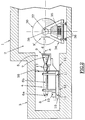
- FIGS. 1 and 2 there is shown schematically an enclosure 1 made of reinforced concrete defining a radiation cell 2 and an adjacent enclosure 3 also made of reinforced concrete forming a casemate in which is placed an electron generator 4, the two enclosures 1 , 3 communicating by a horizontal passage 5 of rectangular section.
- the electron generator comprises an electron gun assembly 6a-accelerating section 6b provided at its end with a scanning horn 7 comprising an exit window of narrow rectangular shape generally arranged vertically to the axis, symbolized at 8, of the beam of electrons, the barrel-accelerator section being arranged horizontally in the casemate 3 in the direction of the irradiation cell 2.
- a conversion target 9 retractable mounted if it is desired to substitute for the radiation electron beam an X-ray radiation beam.
- the assembly formed by the electron gun 6a and the accelerating section 6b, the horn 7, the target 9 and all or part of the servicing means of the accelerator is mounted on a platform 10 movable in block 3 along an axis parallel to axis 8 of the electron beam generated by the accelerator.
- the platform 10 is simply symbolized in the drawings and moves by means of rollers 11 circulating on fixed rails symbolized at 12 installed in the floor slab of the casemate 3.
- the platform 10 is moved for example using onboard motor means 13, the dashed lines connecting the means 13 to the rollers 11 simply illustrating the function of movement of the platform 10 by the means 13, it being understood that many technical solutions known to those skilled in the art are possible for moving the movable assembly consisting of the platform 10 and all the elements which it carries along the rails 12 .
- the easing means of the accelerator on board the mobile platform 10 are not shown in FIG. 2.
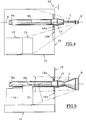
- FIGS. 3 to 5 are complementary views of the mobile assembly of FIG. 2, the tank 14 of a klystron supplying the electron gun 6a and the delay line 15 of the accelerator modulator.
- These means are particularly sensitive to electromagnetic radiation, in particular X-rays back-scattered by the target 9 in the direction of block 3.
- said mobile assembly is provided on its front face facing the irradiation cell 2 with a shield 16 arranged vertically, fixed on the platform 10 and surrounding, in the embodiment shown, the electron accelerator at the height of the assembly 17 for scanning the electron beam interposed between the accelerator section 6b and the horn 9.
- the shield 16 is generally rectangular in shape and corresponds in shape and dimensions to the section of the passage 5.
- the interval between the edges of the shield 16 and the wall of the passage 5 must be as small as possible, on the one hand, to avoid maximum penetration into casemate 3 of X-rays in particular and, on the other hand, to allow correct establishment in casemate 3 of a slight overpressure in fresh air prohibiting in particular the nitric compounds generated in the irradiation cell, generally it - even in slight depression, to enter the casemate 3.
- edges of the shield 16 and the wall of passage 5 may be provided, as shown in dashed lines in 18 in FIG. 4, d '' a strip mounted sliding on the shield and allowing to adjust in situ more finely the interval separating the shield from the wall of the passage.
- the shield 16 is for example a steel plate.
- the shield 16 preferably consists of several parts of different thickness and of shape and layout suitable for the desired purpose.
- the shield 16 has parts of substantially increased thickness while the rest of the shield may have a reduced thickness.
- the shield 16 comprises a first part 16a of reinforced thickness, about ten centimeters for example, of substantially annular shape and surrounding the scanning section 17 and a second part 16b, of same thickness, of generally rectangular shape and substantially arranged in the center of the shield in extension of the part 16a, the rest of the shield having for example a thickness of the order of a centimeter.
- part 16a forms a screen for the accelerating section 6 against the X-rays back-scattered by the target 9.
- the devices 14, 15 are protected both by part 16a and by part 16b.
- Figures 7a, 7b illustrate very schematically an alternative embodiment for pivoting around the axis (8) of the accelerator, the horn-target assembly, in one direction or the other, of at least 90 °, from the so-called normal position, namely the vertical position of the window exit from the horn 7 (FIG. 7a).
- the horn 7 is integral with a connecting ring 6c interposed between the horn 7 and the accelerator section 6b and rotatably mounted on the latter.
- the rotation of the ring 6c is carried out for example by an electric motor 19 mounted on the platform 10 and driving the ring 6c by a chain 20 and a pinion 21 integral with said ring.
- the target 9 is arranged opposite the exit window of the horn 7 and, in the known manner, is mounted retractable laterally when the device is simply used for electronic irradiation.
- the target 9 is mounted at the end of an arm 22 disposed under the horn 7 and capable of pivoting on a support 23, by all appropriate means (not shown) around a vertical axis 24 perpendicular to the 'axis 8.
- the support 23 is integral with the rotary ring 6c.
- the target 9 In the working position, the target 9 has a plane perpendicular to the axis 8.
- the position of the horn 7-target pair 9 is symbolically represented in FIG. 7b after rotation by 90 °, the horn then being horizontal.
- the accelerator is moreover provided, in the known manner, with a calorimetric target, retractable in the manner of the target 9 and therefore carried by the support 23, such a calorimetric target not being shown in the drawings.
- the structure to be irradiated shown diagrammatically at 30 in FIGS. 2 and 6 has a cylindrical shape (ferrule 31) and rounded ends 32. It is supported horizontally at its two ends between two dolls, one of which is driving, on a carriage 34 provided with drive means 35 along rails 36 penetrating into the irradiation cell 2 orthogonally to the axis 8 of the electron beam.
- the structure 30 is rotated on its carriage 34 by a motor 37.
- the dolls (33) for supporting and driving the structure 30 are mounted adjustable in height on the carriage 34.
- the structure 30 is in the known manner presented in front of the horn 7 with its horizontal axis 38 and perpendicular to the axis of the electron beam 8 and passes in front of the horn by being driven by a double movement, of translation along the rails 36 and rotation about its axis 38.
- FIGS 1, 2 and 6, there is shown (at 7, 9) the initial position, of rest, of the horn and of the accelerator target, the target 9 being in the vicinity of the outlet of passage 5 in the irradiation cell 2, while the shield 16 is at the other end of the passage, on the casemate side 3.
- the target 9 can be brought as close as possible to the external wall of the structure both at the level of the ferrule 31 (target 9 ") and at height convex parts 32 (target 9 "'and 9').
- the movement of the platform 10 is controlled by that of the movement of the carriage 34 on its rails 36.
- the various movements of translation of the carriage 34, of the platform 10, and of rotation of the structure 30 are programmed and managed by the accelerator pilot according to the doses of X-radiation sent to the different parts of composite material of said structure, that is to say the parts generally having a surface mass greater than 4 g / cm 2 .
- the movement of the target 9 relative to the structure to be irradiated 30 does not require any adjustment of the incident electron beam since it is the horn 7-target 9 assembly which moves in one block.
- the shield 16 permanently ensures its protective role by sliding in the passage while maintaining substantially the same gap or clearance between it and the wall of the passage, this clearance being reduced as much as possible.
- the translational movement of the platform 10 is ensured at a slow speed and with programmed acceleration and deceleration ramps so as not to generate vibrations which are detrimental to certain components of the on-board equipment, which are particularly fragile.
- the movement of the platform can advantageously be done at two speeds, one relatively fast (the accelerator not being in service) to bring the target 9 into the work area and the other, slow, in progress of structure irradiation.
- the invention applies to the irradiation of structures of revolution (cylindrical, conical, spherical, etc.), but also to the irradiation of structures of any morphology and size and which is not of revolution.
- structure is understood to mean any body or simple or complex part, thick (with variable thickness or not) or massive, comprising or not inserts of a different nature from that of the resin to be polymerized.
- the pivoting of the horn 7-target 9 assembly around the axis 8 of the incident electron beam, thanks to the motor 19, makes it possible to orient the X-ray emission spectrum with respect to the part of the structure to irradiate. This allows a different treatment of different areas of the structure as well as a more effective and targeted treatment of structure or elongated parts of structure, that is to say arranged horizontally at the time of irradiation.
- the pivoting of the horn 7 around the axis 8 can of course be implemented with the target 9 laterally retracted, the device operating in electronic irradiation.
Landscapes
- Health & Medical Sciences (AREA)
- Physics & Mathematics (AREA)
- Engineering & Computer Science (AREA)
- General Engineering & Computer Science (AREA)
- Thermal Sciences (AREA)
- Oral & Maxillofacial Surgery (AREA)
- Toxicology (AREA)
- High Energy & Nuclear Physics (AREA)
- Chemical & Material Sciences (AREA)
- Composite Materials (AREA)
- Mechanical Engineering (AREA)
- Radiation-Therapy Devices (AREA)
- Particle Accelerators (AREA)
- Apparatus For Disinfection Or Sterilisation (AREA)
- Polymerisation Methods In General (AREA)
Abstract
Description
- La présente invention se rapporte à une installation de polymérisation par ionisation de structures, notamment de dimensions importantes, constituées principalement de matériaux composites et plus précisément d'irradiation par rayons X ou électrons des résines entrant dans la composition des matériaux composites, en particulier, bien que non exclusivement, de pièces complexes de révolution telles que par exemple des enceintes ou réservoirs cylindriques à extrémités hémisphériques ou analogues.
- On sait déjà depuis plusieurs années traiter des pièces en matériau composite constitué de fibres, tissus, feutres en verre, Kevlar, carbone et autres matériaux, d'une résine radiodurcissable et d'éléments d'assemblage et/ou d'inserts notamment métalliques ou autres types de matériaux, ledit matériau composite pouvant présenter une forte épaisseur, en soumettant ce matériau à une irradiation par un rayonnement électronique ou X afin de polymériser ou réticuler la résine sans échauffement.
- Pour plus de détails sur une telle technique, on pourra se reporter utilement au brevet européen EP-0.165.118 déposé au nom de la Demanderesse et plus particulièrement destiné au traitement de pièces de révolution allongées telles que des tubes.
- Ce document décrit en particulier une installation de polymérisation/réticulation comprenant des moyens pour produire un faisceau d'électrons, des moyens pour diriger le faisceau d'électrons vers la pièce à traiter, une cible apte à engendrer sous l'action du faisceau d'électrons un rayonnement X, des moyens pour placer la cible sur la trajectoire des électrons ou en dehors de celle-ci afin d'irradier la pièce respectivement avec un rayonnement X ou avec un rayonnement électronique et des moyens pour effectuer un mouvement relatif entre le faisceau irradiant et la pièce afin que celle-ci soit soumise en tout ou partie à l'action de l'un desdits rayonnements.
- Le mouvement relatif en question consiste en un déplacement de la pièce suivant son axe, horizontalement et orthogonalement à l'axe du faisceau irradiant, combiné à une rotation de la pièce autour de son axe.
- Par ailleurs, les doses nécessaires à l'irradiation de la résine du matériau composite de la pièce en vue de sa polymérisation étant fonction dans le cas du rayonnement X de la distance entre la cible et la pièce, il est prévu de régler cette distance et, ce, notamment pour optimiser le temps de polymérisation.
- Deux modes d'action sont envisagés : la pièce est placée de manière à pouvoir être rapprochée ou éloignée de la cible, ou bien l'axe de la pièce est maintenu fixe et la cible est déplacée en direction de la pièce.
- Dans l'installation décrite et représenté dans EP 0.165.118, le générateur d'électrons est monté fixe dans sa casemate de protection, le canon à électrons étant disposé verticalement et tourné vers le sol. Le cornet de balayage du générateur traverse par une fenêtre un bouclier horizontal séparant ladite casemate de la cellule d'irradiation sousjacente dans laquelle se déplace la pièce à irradier, portée par un chariot approprié.
- La pièce, un tube allongé en matériau composite, peut défiler sous le cornet du générateur, une cible de conversion étant interposée entre ce cornet et la pièce lorsque l'on veut irradier cette dernière avec un rayonnement X.
- Conformément au second mode de réglage de la distance entre cible et pièce, la cible escamotable est en outre montée mobile suivant l'axe du faisceau irradiant.
- Si un tel montage permet de mieux régler les doses d'irradiation nécessaires en particulier en cas d'épaisseur importante de matériau composite, et est adapté au type de pièce à traiter, à savoir des pièces tubulaires, il présente néanmoins deux inconvénients majeurs.
- D'une part, il oblige à une modification de la concentration du faisceau d'électrons frappant la cible lorsque la distance entre celle-ci et la fenêtre de sortie du cornet est modifiée.
- En effet, le faisceau d'électrons tel que géométriquement défini par la fenêtre de sortie du cornet est légèrement divergent en sorte qu'un éloignement de la cible entraîne une diminution corrélative de la concentration du faisceau d'électrons sur la cible et donc de l'intensité du rayonnement X engendré.
- Pour remedier à cela, on pourrait dimensionner en conséquence la cible, mais l'accroissement de la surface de la cible trouverait rapidemant ses limites, d'une part, au point de vue géométrique et, d'autre part, au point de vue mécanique, car il se pose des problèmes de refroidissement et de tenue de la cible qui est une plaque mince soumise sur sa face interne à un refroidissement et à un vide poussé.
- Par suite, on ne peut pas se permettre un grand débattement de la cible autour de sa position optimale par rapport au cornet, sauf à utiliser un accélérateur d'électrons surpuissant, ce qui n'est pas non plus satisfaisant.
- L'obligation de correction de la concentration corrélative du faisceau d'électrons sortant du cornet rend donc plus complexe et délicate la gestion des moyens d'asservissement du dispositif d'irradiation.
- D'autre part, les limites pratiques du déplacement de la cible relativement au cornet réduisent considérablement les capacités du dispositif d'irradiation.
- Si ce dernier peut convenir pour traiter des pièces tubulaires du type représenté dans le document cité plus haut dont les parties composites se situent dans une fourchette de distance vis à vis du cornet relativement étroite, encore que, d'une pièce à une autre, il faille modifier ou régler le système de montage sur le chariot de déplacement pour positionner correctement les parties composites en éloignement vis à vis du cornet qui est fixe, ledit dispositif d'irradiation ne peut traiter des pièces dont la géométrie est telle que les parties en matériau composite se situent dans une plage d'éloignement par rapport à l'axe de la pièce très importante, ce qui est par exemple le cas des parties d'extrémités bombées, hémisphériques ou autres, des enceintes ou réservoirs évoqués plus haut.
- Certes, dans un tel cas, la difficulté pourrait être surmontée en prévoyant, en plus de la mobilité de la cible par rapport à la pièce, une mobilité, dans l'axe du faisceau irradiant, de la pièce sur son chariot transporteur.
- Malheureusement, une telle solution rend encore plus complexe, coûteuse et délicate à asservir l'installation d'irradiation, car il faut de surcroît concevoir des chariots transporteurs spéciaux et les asservir en conséquence pour ce qui concerne l'éloignement de la pièce vis à vis du générateur à électrons.
- La présente invention vise à pallier les inconvénients d'un tel dispositif d'irradiation en le perfectionnant afin de le rendre capable de traiter notamment des pièces de révolution de dimensions importantes et présentant des parties en matériau composite se trouvant dans une plage d'éloignement par rapport à l'axe de la pièce très importante, telles que des enceintes ou réservoirs cylindriques à extrémités bombées dont la paroi ou partie de paroi en matériau composite, non seulement peut présenter une épaisseur évolutive, mais peut se situer à une distance de l'axe de plusieurs dizaines de centimètres ou seulement de quelques centimètres, selon que l'on considère respectivement la virole cylindrique ou la zone polaire des extrémités bombées.
- A cet effet, l'invention a pour objet une installation de polymérisation par ionisation de structures notamment de dimensions importantes, constituées principalement de matériaux composites, comprenant :
- un générateur d'électrons disposé dans une casemate et comprenant un accélérateur linéaire muni d'un cornet à fenêtre d'irradiation et des moyens de servitude dudit accélérateur,
- une cible de conversion du faisceau d'électrons en rayonnement X montée escamotable de façon à s'interposer ou non dans le faisceau de sortie dudit cornet,
- une cellule d'irradiation contenant la structure à traiter,
- et des moyens de support-présentation de ladite structure en regard du faisceau d'électrons ou du rayonnement X,
- De préférence, une légère surpression en air neuf est créée dans la casemate afin d'éviter l'entrée de composés nitriques en provenance de la cellule d'irradiation, éventuellement des réglettes de réglage d'écartement entre le bord périphérique du bouclier et la paroi dudit passage, étant montées sur le bouclier, afin d'ajuster ledit écartement aux particularités dimensionnelles de ladite paroi.
- Le bouclier est avantageusement formé de plusieurs parties de caractéristiques, notamment d'épaisseur, variables et géométriquement agencées en sorte de protéger vis à vis du rayonnement X et/ou du rayonnement électronique rétro-diffusé, chaque zone sensible dudit équipage mobile selon son degré de sensibilité et, ce, afin de réduire le plus possible le poids dudit bouclier.
- L'installation de l'invention est particulièrement adaptée à l'irradiation de structures allongées de révolution et de dimensions importantes, notamment des structures de formes générales cylindriques à extrémités bombées.
- Ces structures sont avantageusement placées sur un chariot susceptible de se déplacer dans la cellule d'irradiation de façon que la structure défile devant le cornet de l'accélérateur suivant un mouvement combiné de translation dans l'axe de la structure, cet axe demeurant horizontale et perpendiculaire et de rotation de la structure autour de cet axe sur son chariot porteur, à la manière connue.
- Ainsi, sans avoir à translater latéralement la structure ou son chariot, la cible d'irradiation en X peut être approchée au plus près notamment des parties bombées d'extrémité, de manière efficace et sans avoir à faire de correction compensatoire sur le faisceau d'électrons puisque la distance entre la fenêtre de sortie du cornet de l'accélérateur et la cible n'est pas modifiée.
- L'équipage mobile d'irradiation peut ainsi, à titre d'exemple se déplacer en translation en direction de la structure à traiter, sur une distance de 2,5 mètres ce qui permet d'irradier des structures, notamment de révolution, présentant le long de leur axe des différences de diamètre externe ou interne très importantes.
- Suivant encore une autre caractéristique de l'invention, l'ensemble formé par le cornet de l'accélérateur et la cible est monté de façon à pouvoir pivoter autour de l'axe du faisceau d'électrons engendré, de préférence de part et d'autre d'une position dite d'origine correspondant à la position verticale de la fenêtre de sortie du cornet et d'une amplitude d'au moins 90°.
- D'autres caractéristiques et avantages ressortiront de la description qui va suivre d'un mode de réalisation de l'installation selon l'invention, description donnée à titre d'exemple uniquement et en regard des dessins annexés sur lesquels :
- Figure 1 est une vue générale schématique de dessus d'une installation selon l'invention ;
- Figure 2 est une vue en élévation latérale de l'équipage mobile de l'installation ;
- Figure 3 est une vue de face d'un mode de réalisation d'un bouclier, monté sur l'équipage mobile ;
- Figure 4 représente une vue de dessus du dispositif de la figure 3 suivant une coupe horizontale dans l'axe du canon de l'accélérateur ;
- Figure 5 représente une vue en élévation latérale de gauche du dispositif de la figure 3 suivant une coupe verticale dans l'axe du canon de l'accélérateur ;
- Figure 6 est un schéma en vue de dessus illustrant le traitement d'une structure cylindrique à extrémités bombées, et
- Figures 7a et 7b illustrent schématiquement le montage rotatif du cornet de l'accélérateur et de la cible autour de l'axe du faisceau engendré.
- Sur les figures 1 et 2, on a représenté schématiquement une enceinte 1 en béton armé définissant une cellule d'irradiation 2 et une enceinte adjacente 3 également en béton armé formant casemate dans laquelle est disposé un générateur d'électrons 4, les deux enceintes 1, 3 communiquant par un passage horizontal 5 de section rectangulaire.
- Le générateur d'électrons comprend un ensemble canon à électrons 6a-section accélératrice 6b muni à son extrémité d'un cornet de balayage 7 comportant une fenêtre de sortie de forme rectangulaire étroite disposée généralement verticalement à l'axe, symbolisé en 8, du faisceau d'électrons, l'ensemble canon-section accélératrice étant disposé horizontalement dans la casemate 3 en direction de la cellule d'irradiation 2.
- Immédiatement en avant du cornet 7 peut être placé, à la manière connue, une cible de conversion 9, montée escamotable si l'on veut substituer au faisceau d'électrons d'irradiation un faisceau d'irradiation par rayonnement X.
- Conformément à l'invention, l'ensemble formé par le canon à électrons 6a et la section accélératrice 6b, le cornet 7, la cible 9 et tout ou partie des moyens de servitude de l'accélérateur, est monté sur une plate-forme 10 mobile dans la casemate 3 suivant un axe parallèle à l'axe 8 du faisceau d'électrons engendré par l'accélérateur.
- La plate-forme 10 est simplement symbolisée sur les dessins et se déplace par l'intermédiaire de galets 11 circulant sur des rails fixes symbolisés en 12 installés dans la dalle de plancher de la casemate 3. La plate-forme 10 est mue par exemple à l'aide de moyens moteurs 13 embarqués, les lignes en tiretés reliant les moyens 13 aux galets 11 illustrant simplement la fonction de déplacement de la plate-forme 10 par les moyens 13, étant entendu que bien des solutions techniques connues de l'homme de métier sont possibles pour faire déplacer le long des rails 12 l'équipage mobile constitué de la plate-forme 10 et de tous les éléments qu'elle porte.
- Les moyens de servitude de l'accélérateur embarqués sur la plate-forme mobile 10 ne sont pas représentés sur la figure 2.
- Ces moyens comprennent, entre autres, et comme illustré schématiquement sur les figures 3 à 5 qui sont des vues complémentaires de l'équipage mobile de la figure 2, la cuve 14 d'un klystron alimentant le canon à électrons 6a et la ligne à retard 15 du modulateur de l'accélérateur.
- Ces moyens sont particulièrement sensibles aux rayonnements électromagnétiques, notamment les rayonnements X rétro-diffusés par la cible 9 en direction de la casemate 3.
- Aussi, conformément à une autre caractéristique du dispositif de l'invention, ledit équipage mobile est muni sur sa face frontale tournée vers la cellule d'irradiation 2 d'un bouclier 16 disposé verticalement, fixé sur la plate-forme 10 et entourant, dans le mode de réalisation représenté, l'accélérateur d'électrons à hauteur de l'ensemble 17 de balayage du faisceau d'électrons interposé entre la section accélératrice 6b et le cornet 9.
- Le bouclier 16 est de forme générale rectangulaire et correspond en forme et dimensions à la section du passage 5. L'intervalle entre les bords du bouclier 16 et la paroi du passage 5 doit être aussi faible que possible, d'une part, pour éviter au maximum la pénétration dans la casemate 3 des rayonnements X notamment et, d'autre part, pour permettre d'établir correctement dans la casemate 3 une légère surpression en air neuf interdisant notamment aux composés nitriques engendrés dans la cellule d'irradiation, généralement elle-même mise en légère dépression, de pénétrer dans la casemate 3.
- Pour parfaire la réduction des fuites entre les bords du bouclier 16 et la paroi du passage 5, lesdits bords ou certains d'entre eux, suivant la qualité au point de vue géométrique de la surface du passage en regard, peuvent être munis, comme représenté en tiretés en 18 sur la figure 4, d'une réglette montée coulissante sur le bouclier et permettant de régler in situ plus finement l'intervalle séparant le bouclier de la paroi du passage.
- Le bouclier 16 est par exemple une plaque d'acier.
- Pour réduire le poids du bouclier 16, celui-ci est de préférence constitué de plusieurs parties d'épaisseur différente et de forme et implantation appropriées au but recherché. Ainsi, pour préserver efficacement les zones sensibles, notamment la section accélératrice 6b, la cuve du Klystron 14 et la ligne à retard 15, le bouclier 16 comporte des parties d'épaisseur sensiblement accrue alors que le reste du bouclier peut présenter une épaisseur réduite.
- Par exemple, comme illustré par les figures 3 à 5, le bouclier 16 comporte une première partie 16a d'épaisseur renforcée, une dizaine de centimètres par exemple, de forme sensiblement annulaire et entourant la section de balayage 17 et une seconde partie 16b, de même épaisseur, de forme générale rectangulaire et sensiblement disposée au centre du bouclier en prolongement de la partie 16a, le reste du bouclier ayant par exemple une épaisseur de l'ordre du centimètre.
- Comme on peut l'observer sur les figures 4 et 5, la partie 16a forme un écran pour la section accélératrice 6 contre le rayonnement X rétro-diffusé par la cible 9. Quant aux dispositifs 14, 15, ils sont protégés à la fois par la partie 16a et par la partie 16b.
- Les formes, dimensions et implantations dans le bouclier des sections d'épaisseur renforcée seront bien entendu fonction de la situation et de la morphologie des circuits ou dispositifs portés par la plate-forme 10 et qui doivent faire l'objet d'une protection renforcée.
- Les figures 7a, 7b illustrent très schématiquement une variante de réalisation permettant de faire pivoter autour de l'axe (8) de l'accélérateur, l'ensemble cornet-cible, dans un sens ou dans l'autre, d'au moins 90°, à partir de la position dite normale, à savoir la position verticale de la fenêtre de sortie du cornet 7 (figure 7a).
- A cet effet, le cornet 7 est solidaire d'un anneau de liaison 6c interposé entre le cornet 7 et la section accélératrice 6b et monté rotatif sur cette dernière.
- La rotation de l'anneau 6c est réalisée par exemple par un moteur électrique 19 monté sur la plate-forme 10 et entraînant l'anneau 6c par une chaîne 20 et un pignon 21 solidaire dudit anneau.
- La cible 9 est disposée en regard de la fenêtre de sortie du cornet 7 et, à la manière connue, est montée escamotable latéralement lorsque le dispositif est simplement utilisé pour une irradiation électronique.
- A cet effet, la cible 9 est montée à l'extrémité d'un bras 22 disposé sous le cornet 7 et susceptible de pivoter sur un support 23, par tous moyens appropriés (non représentés) autour d'un axe vertical 24 perpendiculaire à l'axe 8. Le support 23 est solidaire de l'anneau rotatif 6c.
- En position de travail, la cible 9 présente un plan perpendiculairement à l'axe 8.
- Il est clair qu'en actionnant le moteur 19, dans un sens ou dans l'autre, l'ensemble anneau 6c-cornet 7- cible 9 va pivoter autour de l'axe 8 dans un sens ou dans l'autre, du degré désiré.
- On a représenté symboliquement en figure 7b la position du couple cornet 7-cible 9 après rotation de 90°, le cornet étant alors à l'horizontale.
- L'accélérateur est par ailleurs muni, à la manière connue, d'une cible calorimétrique, escamotable à la manière de la cible 9 et donc portée par le support 23, une telle cible calorimétrique n'étant pas représentée les dessins.
- La structure à irradier représentée schématiquement en 30 sur les figures 2 et 6 a une forme cylindrique (virole 31) et des extrémités bombées 32. Elle est supportée à l'horizontale à ses deux extrémités entre deux poupées dont l'une 33 est motrice, sur un chariot 34 pourvu de moyens d'entraînement 35 le long de rails 36 pénétrant dans la cellule d'irradiation 2 orthogonalement à l'axe 8 du faisceau d'électrons.
- La rotation de la structure 30 sur son chariot 34 est assurée par un moteur 37.
- Eventuellement, les poupées (33) de support-entraînement de la structure 30 sont montées réglables en hauteur sur le chariot 34.
- La structure 30 est à la manière connue présentée devant le cornet 7 avec son axe 38 horizontal et perpendiculaire à l'axe du faisceau d'électrons 8 et défile devant le cornet en étant animée d'un double mouvement, de translation le long des rails 36 et de rotation autour de son axe 38.
- Sur les figures 1, 2 et 6, on a représenté (en 7, 9) la position initiale, de repos, du cornet et de la cible de l'accélérateur, la cible 9 se trouvant au voisinage du débouché du passage 5 dans la cellule d'irradiation 2, cependant que le bouclier 16 se trouve à l'autre extrémité du passage, côté casemate 3.
- En 7' et 9' sont représentées les positions d'avancée extrême du cornet et de la cible vis à vis de l'axe 38 de la structure à irradier. La course d de déplacement de l'équipage mobile (figures 2 et 6) est de l'ordre par exemple de 2,5 mètres.
- Comme illustré par la figure 6, selon la morphologie de la structure 30 à irradier, la cible 9 peut être amenée au plus près de la paroi externe de la structure aussi bien à hauteur de la virole 31 (cible 9") qu'à hauteur des parties bombées 32 (cible 9"' et 9').
- Bien entendu, le déplacement de la plate-forme 10 est asservi à celui du déplacement du chariot 34 sur ses rails 36.
- D'une manière générale, les divers mouvements de translation du chariot 34, de la plate-forme 10, et de rotation de la structure 30 sont programmés et gérés par le pilote de l'accélérateur en fonction des doses de rayonnement X envoyées sur les différentes parties en matériau composite de ladite structure, c'est à dire les parties présentant d'une manière générale une masse surfacique supérieure à 4g/cm2.
- Comme indiqué plus haut, le déplacement de la cible 9 par rapport à la structure à irradier 30 ne nécessite aucun réglage du faisceau d'électrons incidents puisque c'est l'ensemble cornet 7-cible 9 qui se déplace d'un bloc.
- Tout au long de son déplacement dans le passage 5, le bouclier 16 assure en permanence son rôle protecteur en coulissant dans le passage tout en conservant sensiblement le même intervalle ou jeu entre lui et la paroi du passage, ce jeu étant réduit le plus possible.
- Le déplacement en translation de la plate-forme 10 est assuré à une vitesse lente et avec des rampes d'accélération et décélération programmées afin de ne pas engendrer de vibrations préjudiciables à certains composants du matériel embarqué, particulièrement fragiles.
- Le déplacement de la plate-forme peut se faire avantageusement à deux vitesses, l'une relativement rapide (l'accélérateur n'étant pas en service) pour amener la cible 9 dans la zone de travail et l'autre, lente, en cours d'irradiation de la structure.
- L'invention s'applique à l'irradiation de structures de révolution (cylindrique, conique, sphérique, etc...), mais également à l'irradiation de structure de toute morphologie et dimension et qui n'est pas de révolution. Par structure, on entend tous corps ou pièces simple ou complexe, épaisses (à épaisseur variable ou non) ou massives, comportant ou non des inserts de nature différente de celle de la résine à polymériser.
- Le pivotement de l'ensemble cornet 7- cible 9 autour de l'axe 8 du faisceau d'électrons incidents, grâce au moteur 19, permet d'orienter le spectre d'émission des rayons X par rapport à la partie de la structure à irradier. Ceci autorise un traitement différent de zones différentes de la structure ainsi qu'un traitement plus efficace et ciblé de structure ou de parties de structure allongées, c'est-à-dire disposées horizontalement au moment de l'irradiation.
- Le pivotement du cornet 7 autour de l'axe 8 peut bien entendu être mis en oeuvre avec la cible 9 escamotée latéralement, le dispositif fonctionnant en irradiation électronique.
- Enfin l'invention, n'est évidemment pas limitée aux modes de réalisation représentés et décrits ci-dessus mais en couvre au contraire toutes les variantes, notamment en ce qui concerne la technologie de réalisation des divers moyens pour translater la plate-forme 10.
Claims (6)
- Installation de polymérisation par ionisation de structures notamment de dimensions importantes, constituées principalement de matériaux composites, comprenant :- un générateur d'électrons (4) disposé dans une casemate (3) et comprenant un accélérateur linéaire (6) muni d'un cornet (7) à fenêtre d'irradiation et des moyens de servitude dudit accélérateur,- une cible (9) de conversion du faisceau d'électrons en rayonnement X, montée escamotable, de façon à s'interposer ou non dans le faisceau de sortie dudit cornet,- une cellule d'irradiation (2) contenant la structure (30) à traiter,- et des moyens (34) de support-présentation de ladite structure (30) en regard du faisceau d'électrons ou du rayonnement X,caractérisée en ce que l'ensemble accélérateur (4)-cornet (7)-cible (9) et une partie au moins des moyens de servitude (14,15) est embarqué sur une plate-forme mobile dans la casemate (3) en direction de la cellule d'irradiation (2) et suivant un axe horizontal parallèle à l'axe (8) du faisceau engendré par l'accélérateur et en ce que l'équipage mobile ainsi constitué est muni, sur sa face frontale tournée vers la cellule d'irradiation (2), d'un bouclier de radio-protection (16) susceptible de se déplacer dans un passage (5) ménagé dans une paroi de séparation entre la cellule d'irradiation (2) et la casemate (3), le contour du bouclier étant adapté à la section dudit passage en sorte de ne laisser subsister entre ledit contour et ledit passage qu'un intervalle aussi réduit que possible.
- Installation suivant la revendication 1, caractérisée en ce qu'une légère surpression en air neuf est créée dans la casemate (3) afin d'éviter l'entrée de composés nitriques en provenance de la cellule d'irradiation (2).
- Installation suivant la revendication 1 ou 2, caractérisée en ce que des réglettes (18) de réglage d'écartement entre le bord périphérique du bouclier (16) et la paroi dudit passage (5) sont montées sur le bouclier.
- Installation suivant l'une des revendications 1 à 3, caractérisée en ce que le bouclier (16) est formé de plusieurs parties (16a, 16b) de caractéristiques, notamment d'épaisseur, variables et géométriquement agencées en sorte de protéger vis à vis du rayonnement X et/ou du rayonnement électronique rétro-diffusé, chaque zone sensible dudit équipage mobile selon son degré de sensibilité.
- Installation suivant l'une des revendications 1 à 4, caractérisée en ce que la structure à irradier (30) est une structure de révolution défilant devant le cornet (7) de l'accélérateur avec son axe (38) horizontal perpendiculaire à l'axe (8) du faisceau d'électrons de l'accélérateur et soumise à un double mouvement de rotation autour de son axe et de translation suivant son axe, les mouvements de la plate-forme (10) et de la structure (30) à irradier étant asservis.
- Installation suivant l'une des revendications 1 à 5, caractérisée en ce que l'ensemble cornet (7)-cible (9) est monté rotatif autour de l'axe (8) de l'accélérateur, dans un sens ou dans l'autre et d'une amplitude au moins égale à 90°.
Applications Claiming Priority (2)
| Application Number | Priority Date | Filing Date | Title |
|---|---|---|---|
| FR9414881A FR2727683A1 (fr) | 1994-12-05 | 1994-12-05 | Installation de polymerisation par ionisation de structures notamment de dimensions importantes constituees principalement de materiaux composites |
| FR9414881 | 1994-12-05 |
Publications (2)
| Publication Number | Publication Date |
|---|---|
| EP0715936A1 true EP0715936A1 (fr) | 1996-06-12 |
| EP0715936B1 EP0715936B1 (fr) | 1999-06-02 |
Family
ID=9469671
Family Applications (1)
| Application Number | Title | Priority Date | Filing Date |
|---|---|---|---|
| EP95450018A Expired - Lifetime EP0715936B1 (fr) | 1994-12-05 | 1995-12-01 | Installation de polymérisation par ionisation de structures notamment de dimensions importantes constituées principalement de matériaux composites |
Country Status (7)
| Country | Link |
|---|---|
| US (1) | US5636257A (fr) |
| EP (1) | EP0715936B1 (fr) |
| JP (1) | JPH093110A (fr) |
| KR (1) | KR960021492A (fr) |
| CA (1) | CA2164261A1 (fr) |
| DE (1) | DE69510011T2 (fr) |
| FR (1) | FR2727683A1 (fr) |
Cited By (1)
| Publication number | Priority date | Publication date | Assignee | Title |
|---|---|---|---|---|
| WO1999052650A1 (fr) * | 1998-04-11 | 1999-10-21 | Fraunhofer-Gesellschaft zur Förderung der angewandten Forschung e.V. | Procede pour bombarder electroniquement des couches appliquees sur des surfaces d'objets, et dispositif pour mettre en oeuvre ledit procede |
Families Citing this family (4)
| Publication number | Priority date | Publication date | Assignee | Title |
|---|---|---|---|---|
| US6504898B1 (en) * | 2000-04-17 | 2003-01-07 | Mds (Canada) Inc. | Product irradiator for optimizing dose uniformity in products |
| DE10250988A1 (de) * | 2002-10-28 | 2004-05-13 | Gamma-Service Produktbestrahlung Gmbh | Elektronenbestrahlungsanlage |
| CN103971780B (zh) * | 2013-12-24 | 2016-07-06 | 中国科学院上海应用物理研究所 | 用于辐照加速器x射线转换靶的支承装置 |
| CN106932809B (zh) * | 2015-12-30 | 2023-07-14 | 核工业西南物理研究院 | 一种w字形多板变角组合结构的主动水冷量热靶结构 |
Citations (7)
| Publication number | Priority date | Publication date | Assignee | Title |
|---|---|---|---|---|
| GB869267A (en) * | 1958-07-04 | 1961-05-31 | Bbc Brown Boveri & Cie | Improvements in or relating to radiation plant |
| FR1296844A (fr) * | 1960-08-01 | 1962-06-22 | Varian Associates | Procédé et dispositif pour diriger les radiations à grande énergie |
| GB987884A (en) * | 1962-02-14 | 1965-03-31 | Medicor Rontgen Muvek | Gamma-ray irradiation apparatus |
| FR2298166A1 (fr) * | 1975-01-15 | 1976-08-13 | Tetzlaff Karl Heinz | Installation d'irradiation gamma perfectionnee |
| FR2488766A1 (fr) * | 1980-08-18 | 1982-02-19 | IVANOV Andrei | Accelerateur d'electrons |
| EP0105580A2 (fr) * | 1982-09-30 | 1984-04-18 | Radiation Dynamics Inc. | Dispositif d'irradiation pour des objets de forme cylindrique |
| EP0165118A1 (fr) | 1984-05-11 | 1985-12-18 | AEROSPATIALE Société Nationale Industrielle | Procédé et dispositif de polymérisation et/ou de réticulation d'une résine entrant dans la composition d'une pièce en matériau composite au moyen de rayonnements ionisants |
Family Cites Families (3)
| Publication number | Priority date | Publication date | Assignee | Title |
|---|---|---|---|---|
| US3360647A (en) * | 1964-09-14 | 1967-12-26 | Varian Associates | Electron accelerator with specific deflecting magnet structure and x-ray target |
| US3482096A (en) * | 1965-08-02 | 1969-12-02 | Field Emission Corp | High energy field emission electron radiation pulse generator,x-ray apparatus and system employing same |
| US3759811A (en) * | 1970-01-16 | 1973-09-18 | Nat Distillers Chem Corp | Apparatus for radiation polymerization |
-
1994
- 1994-12-05 FR FR9414881A patent/FR2727683A1/fr active Granted
-
1995
- 1995-12-01 EP EP95450018A patent/EP0715936B1/fr not_active Expired - Lifetime
- 1995-12-01 CA CA002164261A patent/CA2164261A1/fr not_active Abandoned
- 1995-12-01 DE DE69510011T patent/DE69510011T2/de not_active Expired - Fee Related
- 1995-12-05 JP JP7344490A patent/JPH093110A/ja active Pending
- 1995-12-05 US US08/567,577 patent/US5636257A/en not_active Expired - Fee Related
- 1995-12-05 KR KR1019950046644A patent/KR960021492A/ko not_active Withdrawn
Patent Citations (7)
| Publication number | Priority date | Publication date | Assignee | Title |
|---|---|---|---|---|
| GB869267A (en) * | 1958-07-04 | 1961-05-31 | Bbc Brown Boveri & Cie | Improvements in or relating to radiation plant |
| FR1296844A (fr) * | 1960-08-01 | 1962-06-22 | Varian Associates | Procédé et dispositif pour diriger les radiations à grande énergie |
| GB987884A (en) * | 1962-02-14 | 1965-03-31 | Medicor Rontgen Muvek | Gamma-ray irradiation apparatus |
| FR2298166A1 (fr) * | 1975-01-15 | 1976-08-13 | Tetzlaff Karl Heinz | Installation d'irradiation gamma perfectionnee |
| FR2488766A1 (fr) * | 1980-08-18 | 1982-02-19 | IVANOV Andrei | Accelerateur d'electrons |
| EP0105580A2 (fr) * | 1982-09-30 | 1984-04-18 | Radiation Dynamics Inc. | Dispositif d'irradiation pour des objets de forme cylindrique |
| EP0165118A1 (fr) | 1984-05-11 | 1985-12-18 | AEROSPATIALE Société Nationale Industrielle | Procédé et dispositif de polymérisation et/ou de réticulation d'une résine entrant dans la composition d'une pièce en matériau composite au moyen de rayonnements ionisants |
Non-Patent Citations (1)
| Title |
|---|
| BEZIERS D ET AL: "ELECTRON BEAM CURING OF COMPOSITES", COMPOSITE POLYMERS, vol. 3, no. 6, 1 January 1990 (1990-01-01), pages 438 - 451, XP000226334 * |
Cited By (1)
| Publication number | Priority date | Publication date | Assignee | Title |
|---|---|---|---|---|
| WO1999052650A1 (fr) * | 1998-04-11 | 1999-10-21 | Fraunhofer-Gesellschaft zur Förderung der angewandten Forschung e.V. | Procede pour bombarder electroniquement des couches appliquees sur des surfaces d'objets, et dispositif pour mettre en oeuvre ledit procede |
Also Published As
| Publication number | Publication date |
|---|---|
| FR2727683A1 (fr) | 1996-06-07 |
| CA2164261A1 (fr) | 1996-06-06 |
| FR2727683B1 (fr) | 1997-02-28 |
| KR960021492A (ko) | 1996-07-18 |
| DE69510011T2 (de) | 2000-01-27 |
| DE69510011D1 (de) | 1999-07-08 |
| JPH093110A (ja) | 1997-01-07 |
| US5636257A (en) | 1997-06-03 |
| EP0715936B1 (fr) | 1999-06-02 |
Similar Documents
| Publication | Publication Date | Title |
|---|---|---|
| EP2979852B1 (fr) | Dispositif de compactage pour machine d'enroulement d'une texture fibreuse sur un mandrin d'imprégnation | |
| EP0119883B1 (fr) | Procédé et dispositif d'alignement d'un faisceau laser par l'intermédiaire de moyens optiques de visée, et procédé de mise en oeuvre du dispositif, pour contrôler l'alignement | |
| BE1013614A3 (fr) | Appareil de determination de la distribution dans l'eau d'une dose de type fantome. | |
| EP3652773B1 (fr) | Source génératrice de rayons ionisants compacte, ensemble comprenant plusieurs sources et procédé de réalisation de la source | |
| FR2706132A1 (fr) | Dispositif de traitement de lésions cérébrales par rayonnement gamma, et appareil de traitement correspondant. | |
| FR2735056A1 (fr) | Installation pour travailler une zone d'un tube au moyen d'un faisceau laser et application aux tubes d'une canalisation sur une barge de pose en mer ou de recuperation de cette canalisation. | |
| EP0715936B1 (fr) | Installation de polymérisation par ionisation de structures notamment de dimensions importantes constituées principalement de matériaux composites | |
| WO2005041241A1 (fr) | Canon a electrons a anode focalisante, formant une fenetre de ce canon, application a l'irradiation et a la sterilisation | |
| EP0197827B1 (fr) | Table d'examen à guidage linéaire d'un panneau d'examen | |
| CA2534310C (fr) | Installation et procede pour la sterilisation d'objets par bombardement d'electrons a faible energie | |
| EP3972771A1 (fr) | Appareil a souder par faisceau d'electrons | |
| EP0060771B1 (fr) | Dispositif de radiographie utilisant l'accélérateur de particules chargées d'un appareil de radiothérapie, et appareil de radiothérapie équipé d'un tel dispositif | |
| WO1994007099A1 (fr) | Dispositif de transfert de pieces de bois dans un four de sechage par micro-ondes | |
| FR2495427A1 (fr) | Procede et installation de traitement par rayonnement electromagnetique tel que faisceau laser, d'une piece composite | |
| EP0499559A1 (fr) | Procédé et dispositif de contrôle non-destructif par interféromètre holographique d'enceintes en matériau composite | |
| FR2735241A1 (fr) | Procede de controle en temps reel du debit de dose de rayonnements ionisants et dispositif pour sa mise en oeuvre | |
| FR2672220A1 (fr) | Appareil de traitement de lesions cerebrales par rayonnement gamma. | |
| EP4231916B1 (fr) | Dispositif de radiologie a sources et detecteur disposes en helice | |
| EP0479344B1 (fr) | Système d'intervention sur les parois internes de la boîte à eau d'un générateur de vapeur de centrale nucleaire | |
| EP0454584B1 (fr) | Procédé et dispositif de décontamination par décapage ionique | |
| FR2652446A1 (fr) | Gyrotron quasi optique. | |
| FR2562724A1 (fr) | Reflecteur d'antenne pour engin spatial et dispositif pour le developpement de ce reflecteur | |
| FR2740714A1 (fr) | Dispositif de coupe de matiere | |
| JPS6353218A (ja) | 管内外面のレ−ザ表層処理装置 | |
| FR3165544A1 (fr) | Source de rayons X et procédé de génération de rayons X et de resurfaçage d’un matériau cible |
Legal Events
| Date | Code | Title | Description |
|---|---|---|---|
| PUAI | Public reference made under article 153(3) epc to a published international application that has entered the european phase |
Free format text: ORIGINAL CODE: 0009012 |
|
| AK | Designated contracting states |
Kind code of ref document: A1 Designated state(s): BE DE GB IT SE |
|
| 17P | Request for examination filed |
Effective date: 19961114 |
|
| GRAG | Despatch of communication of intention to grant |
Free format text: ORIGINAL CODE: EPIDOS AGRA |
|
| 17Q | First examination report despatched |
Effective date: 19980812 |
|
| GRAG | Despatch of communication of intention to grant |
Free format text: ORIGINAL CODE: EPIDOS AGRA |
|
| GRAH | Despatch of communication of intention to grant a patent |
Free format text: ORIGINAL CODE: EPIDOS IGRA |
|
| GRAH | Despatch of communication of intention to grant a patent |
Free format text: ORIGINAL CODE: EPIDOS IGRA |
|
| GRAA | (expected) grant |
Free format text: ORIGINAL CODE: 0009210 |
|
| AK | Designated contracting states |
Kind code of ref document: B1 Designated state(s): BE DE GB IT SE |
|
| REF | Corresponds to: |
Ref document number: 69510011 Country of ref document: DE Date of ref document: 19990708 |
|
| ITF | It: translation for a ep patent filed | ||
| GBT | Gb: translation of ep patent filed (gb section 77(6)(a)/1977) |
Effective date: 19990901 |
|
| PGFP | Annual fee paid to national office [announced via postgrant information from national office to epo] |
Ref country code: SE Payment date: 19991217 Year of fee payment: 5 |
|
| PGFP | Annual fee paid to national office [announced via postgrant information from national office to epo] |
Ref country code: BE Payment date: 19991229 Year of fee payment: 5 |
|
| PLBE | No opposition filed within time limit |
Free format text: ORIGINAL CODE: 0009261 |
|
| STAA | Information on the status of an ep patent application or granted ep patent |
Free format text: STATUS: NO OPPOSITION FILED WITHIN TIME LIMIT |
|
| 26N | No opposition filed | ||
| PG25 | Lapsed in a contracting state [announced via postgrant information from national office to epo] |
Ref country code: SE Free format text: LAPSE BECAUSE OF NON-PAYMENT OF DUE FEES Effective date: 20001202 |
|
| PG25 | Lapsed in a contracting state [announced via postgrant information from national office to epo] |
Ref country code: BE Free format text: LAPSE BECAUSE OF NON-PAYMENT OF DUE FEES Effective date: 20001231 |
|
| BERE | Be: lapsed |
Owner name: AEROSPATIALE SOC. NATIONALE INDUSTRIELLE Effective date: 20001231 |
|
| EUG | Se: european patent has lapsed |
Ref document number: 95450018.7 |
|
| REG | Reference to a national code |
Ref country code: GB Ref legal event code: IF02 |
|
| PGFP | Annual fee paid to national office [announced via postgrant information from national office to epo] |
Ref country code: GB Payment date: 20031128 Year of fee payment: 9 |
|
| PGFP | Annual fee paid to national office [announced via postgrant information from national office to epo] |
Ref country code: DE Payment date: 20040217 Year of fee payment: 9 |
|
| PG25 | Lapsed in a contracting state [announced via postgrant information from national office to epo] |
Ref country code: GB Free format text: LAPSE BECAUSE OF NON-PAYMENT OF DUE FEES Effective date: 20041201 |
|
| PG25 | Lapsed in a contracting state [announced via postgrant information from national office to epo] |
Ref country code: DE Free format text: LAPSE BECAUSE OF NON-PAYMENT OF DUE FEES Effective date: 20050701 |
|
| GBPC | Gb: european patent ceased through non-payment of renewal fee |
Effective date: 20041201 |
|
| PG25 | Lapsed in a contracting state [announced via postgrant information from national office to epo] |
Ref country code: IT Free format text: LAPSE BECAUSE OF NON-PAYMENT OF DUE FEES;WARNING: LAPSES OF ITALIAN PATENTS WITH EFFECTIVE DATE BEFORE 2007 MAY HAVE OCCURRED AT ANY TIME BEFORE 2007. THE CORRECT EFFECTIVE DATE MAY BE DIFFERENT FROM THE ONE RECORDED. Effective date: 20051201 |