EP0716343A1 - Dispositif de traitement automatique pour matériau photographique à l'halogénure d'argent sensible à la lumière - Google Patents
Dispositif de traitement automatique pour matériau photographique à l'halogénure d'argent sensible à la lumière Download PDFInfo
- Publication number
- EP0716343A1 EP0716343A1 EP95119229A EP95119229A EP0716343A1 EP 0716343 A1 EP0716343 A1 EP 0716343A1 EP 95119229 A EP95119229 A EP 95119229A EP 95119229 A EP95119229 A EP 95119229A EP 0716343 A1 EP0716343 A1 EP 0716343A1
- Authority
- EP
- European Patent Office
- Prior art keywords
- processing
- tank
- solution
- sensitive material
- processor
- Prior art date
- Legal status (The legal status is an assumption and is not a legal conclusion. Google has not performed a legal analysis and makes no representation as to the accuracy of the status listed.)
- Granted
Links
- 239000000463 material Substances 0.000 title claims abstract description 231
- -1 silver halide Chemical class 0.000 title claims abstract description 166
- 229910052709 silver Inorganic materials 0.000 title claims abstract description 131
- 239000004332 silver Substances 0.000 title claims abstract description 131
- 238000012545 processing Methods 0.000 claims abstract description 569
- 239000008247 solid mixture Substances 0.000 claims abstract 2
- XLYOFNOQVPJJNP-UHFFFAOYSA-N water Substances O XLYOFNOQVPJJNP-UHFFFAOYSA-N 0.000 claims description 129
- 239000007788 liquid Substances 0.000 claims description 28
- 238000012856 packing Methods 0.000 claims description 6
- 238000005507 spraying Methods 0.000 claims description 3
- 238000000926 separation method Methods 0.000 claims 2
- 238000007599 discharging Methods 0.000 claims 1
- 239000003795 chemical substances by application Substances 0.000 description 201
- 239000007787 solid Substances 0.000 description 99
- 239000003570 air Substances 0.000 description 66
- 238000000034 method Methods 0.000 description 51
- 230000000087 stabilizing effect Effects 0.000 description 38
- 239000003826 tablet Substances 0.000 description 34
- 230000000694 effects Effects 0.000 description 31
- 238000011161 development Methods 0.000 description 24
- 150000001875 compounds Chemical class 0.000 description 21
- 125000000217 alkyl group Chemical group 0.000 description 20
- 230000009467 reduction Effects 0.000 description 19
- 238000007254 oxidation reaction Methods 0.000 description 18
- 230000001965 increasing effect Effects 0.000 description 17
- 230000003647 oxidation Effects 0.000 description 17
- 230000002829 reductive effect Effects 0.000 description 17
- 238000001035 drying Methods 0.000 description 16
- 239000000203 mixture Substances 0.000 description 16
- 230000015271 coagulation Effects 0.000 description 15
- 238000005345 coagulation Methods 0.000 description 15
- 239000007789 gas Substances 0.000 description 15
- 239000008187 granular material Substances 0.000 description 14
- 230000008569 process Effects 0.000 description 14
- 125000003118 aryl group Chemical group 0.000 description 12
- 230000001105 regulatory effect Effects 0.000 description 12
- 230000006866 deterioration Effects 0.000 description 10
- 125000004435 hydrogen atom Chemical group [H]* 0.000 description 10
- 238000003780 insertion Methods 0.000 description 10
- 230000037431 insertion Effects 0.000 description 10
- 238000005192 partition Methods 0.000 description 10
- 239000000843 powder Substances 0.000 description 10
- 125000001495 ethyl group Chemical group [H]C([H])([H])C([H])([H])* 0.000 description 9
- DGAQECJNVWCQMB-PUAWFVPOSA-M Ilexoside XXIX Chemical compound C[C@@H]1CC[C@@]2(CC[C@@]3(C(=CC[C@H]4[C@]3(CC[C@@H]5[C@@]4(CC[C@@H](C5(C)C)OS(=O)(=O)[O-])C)C)[C@@H]2[C@]1(C)O)C)C(=O)O[C@H]6[C@@H]([C@H]([C@@H]([C@H](O6)CO)O)O)O.[Na+] DGAQECJNVWCQMB-PUAWFVPOSA-M 0.000 description 8
- CDBYLPFSWZWCQE-UHFFFAOYSA-L Sodium Carbonate Chemical compound [Na+].[Na+].[O-]C([O-])=O CDBYLPFSWZWCQE-UHFFFAOYSA-L 0.000 description 8
- 239000011734 sodium Substances 0.000 description 8
- 229910052708 sodium Inorganic materials 0.000 description 8
- 125000001424 substituent group Chemical group 0.000 description 8
- 239000002253 acid Substances 0.000 description 7
- 125000003178 carboxy group Chemical group [H]OC(*)=O 0.000 description 7
- 230000001276 controlling effect Effects 0.000 description 7
- 238000007796 conventional method Methods 0.000 description 7
- 238000002474 experimental method Methods 0.000 description 7
- 125000002887 hydroxy group Chemical group [H]O* 0.000 description 7
- BWHMMNNQKKPAPP-UHFFFAOYSA-L potassium carbonate Chemical compound [K+].[K+].[O-]C([O-])=O BWHMMNNQKKPAPP-UHFFFAOYSA-L 0.000 description 7
- 238000004061 bleaching Methods 0.000 description 6
- 239000013078 crystal Substances 0.000 description 6
- 238000010438 heat treatment Methods 0.000 description 6
- 125000000623 heterocyclic group Chemical group 0.000 description 6
- 125000001476 phosphono group Chemical group [H]OP(*)(=O)O[H] 0.000 description 6
- GEHJYWRUCIMESM-UHFFFAOYSA-L sodium sulfite Chemical compound [Na+].[Na+].[O-]S([O-])=O GEHJYWRUCIMESM-UHFFFAOYSA-L 0.000 description 6
- 239000000126 substance Substances 0.000 description 6
- 239000002202 Polyethylene glycol Substances 0.000 description 5
- 125000003277 amino group Chemical group 0.000 description 5
- 125000003917 carbamoyl group Chemical group [H]N([H])C(*)=O 0.000 description 5
- 238000010586 diagram Methods 0.000 description 5
- 229920001223 polyethylene glycol Polymers 0.000 description 5
- 238000003860 storage Methods 0.000 description 5
- 125000000020 sulfo group Chemical group O=S(=O)([*])O[H] 0.000 description 5
- PXHVJJICTQNCMI-UHFFFAOYSA-N Nickel Chemical compound [Ni] PXHVJJICTQNCMI-UHFFFAOYSA-N 0.000 description 4
- WCUXLLCKKVVCTQ-UHFFFAOYSA-M Potassium chloride Chemical compound [Cl-].[K+] WCUXLLCKKVVCTQ-UHFFFAOYSA-M 0.000 description 4
- QAOWNCQODCNURD-UHFFFAOYSA-N Sulfuric acid Chemical compound OS(O)(=O)=O QAOWNCQODCNURD-UHFFFAOYSA-N 0.000 description 4
- 125000000656 azaniumyl group Chemical group [H][N+]([H])([H])[*] 0.000 description 4
- LLEMOWNGBBNAJR-UHFFFAOYSA-N biphenyl-2-ol Chemical compound OC1=CC=CC=C1C1=CC=CC=C1 LLEMOWNGBBNAJR-UHFFFAOYSA-N 0.000 description 4
- 238000004140 cleaning Methods 0.000 description 4
- 238000004891 communication Methods 0.000 description 4
- 238000007689 inspection Methods 0.000 description 4
- 239000006187 pill Substances 0.000 description 4
- 229910000027 potassium carbonate Inorganic materials 0.000 description 4
- 235000011181 potassium carbonates Nutrition 0.000 description 4
- 229910000029 sodium carbonate Inorganic materials 0.000 description 4
- 229940001593 sodium carbonate Drugs 0.000 description 4
- 235000017550 sodium carbonate Nutrition 0.000 description 4
- CUYTYLVEYFUAAX-UHFFFAOYSA-N 4-methylbenzenesulfonic acid;sodium Chemical compound [Na].CC1=CC=C(S(O)(=O)=O)C=C1 CUYTYLVEYFUAAX-UHFFFAOYSA-N 0.000 description 3
- QGZKDVFQNNGYKY-UHFFFAOYSA-O Ammonium Chemical compound [NH4+] QGZKDVFQNNGYKY-UHFFFAOYSA-O 0.000 description 3
- WVDDGKGOMKODPV-UHFFFAOYSA-N Benzyl alcohol Chemical compound OCC1=CC=CC=C1 WVDDGKGOMKODPV-UHFFFAOYSA-N 0.000 description 3
- KCXVZYZYPLLWCC-UHFFFAOYSA-N EDTA Chemical compound OC(=O)CN(CC(O)=O)CCN(CC(O)=O)CC(O)=O KCXVZYZYPLLWCC-UHFFFAOYSA-N 0.000 description 3
- WMFOQBRAJBCJND-UHFFFAOYSA-M Lithium hydroxide Chemical compound [Li+].[OH-] WMFOQBRAJBCJND-UHFFFAOYSA-M 0.000 description 3
- 235000008331 Pinus X rigitaeda Nutrition 0.000 description 3
- 235000011613 Pinus brutia Nutrition 0.000 description 3
- 241000018646 Pinus brutia Species 0.000 description 3
- ZLMJMSJWJFRBEC-UHFFFAOYSA-N Potassium Chemical compound [K] ZLMJMSJWJFRBEC-UHFFFAOYSA-N 0.000 description 3
- KWYUFKZDYYNOTN-UHFFFAOYSA-M Potassium hydroxide Chemical compound [OH-].[K+] KWYUFKZDYYNOTN-UHFFFAOYSA-M 0.000 description 3
- 238000010521 absorption reaction Methods 0.000 description 3
- 125000003545 alkoxy group Chemical group 0.000 description 3
- 125000002947 alkylene group Chemical group 0.000 description 3
- 239000012080 ambient air Substances 0.000 description 3
- 125000004397 aminosulfonyl group Chemical group NS(=O)(=O)* 0.000 description 3
- 238000005282 brightening Methods 0.000 description 3
- 229910052799 carbon Inorganic materials 0.000 description 3
- 230000000052 comparative effect Effects 0.000 description 3
- 230000002354 daily effect Effects 0.000 description 3
- 239000000428 dust Substances 0.000 description 3
- 229960001484 edetic acid Drugs 0.000 description 3
- 238000001704 evaporation Methods 0.000 description 3
- 230000008020 evaporation Effects 0.000 description 3
- 230000003203 everyday effect Effects 0.000 description 3
- 230000006872 improvement Effects 0.000 description 3
- 238000011068 loading method Methods 0.000 description 3
- 238000012423 maintenance Methods 0.000 description 3
- 150000004989 p-phenylenediamines Chemical class 0.000 description 3
- ACVYVLVWPXVTIT-UHFFFAOYSA-N phosphinic acid Chemical group O[PH2]=O ACVYVLVWPXVTIT-UHFFFAOYSA-N 0.000 description 3
- 239000011591 potassium Substances 0.000 description 3
- 229910052700 potassium Inorganic materials 0.000 description 3
- 238000002360 preparation method Methods 0.000 description 3
- 239000001488 sodium phosphate Substances 0.000 description 3
- 235000010265 sodium sulphite Nutrition 0.000 description 3
- 239000004094 surface-active agent Substances 0.000 description 3
- 238000012546 transfer Methods 0.000 description 3
- 239000003232 water-soluble binding agent Substances 0.000 description 3
- CBCKQZAAMUWICA-UHFFFAOYSA-N 1,4-phenylenediamine Chemical compound NC1=CC=C(N)C=C1 CBCKQZAAMUWICA-UHFFFAOYSA-N 0.000 description 2
- BDOYKFSQFYNPKF-UHFFFAOYSA-N 2-[2-[bis(carboxymethyl)amino]ethyl-(carboxymethyl)amino]acetic acid;sodium Chemical compound [Na].[Na].OC(=O)CN(CC(O)=O)CCN(CC(O)=O)CC(O)=O BDOYKFSQFYNPKF-UHFFFAOYSA-N 0.000 description 2
- BTBUEUYNUDRHOZ-UHFFFAOYSA-N Borate Chemical compound [O-]B([O-])[O-] BTBUEUYNUDRHOZ-UHFFFAOYSA-N 0.000 description 2
- VEXZGXHMUGYJMC-UHFFFAOYSA-M Chloride anion Chemical compound [Cl-] VEXZGXHMUGYJMC-UHFFFAOYSA-M 0.000 description 2
- FYYHWMGAXLPEAU-UHFFFAOYSA-N Magnesium Chemical compound [Mg] FYYHWMGAXLPEAU-UHFFFAOYSA-N 0.000 description 2
- JUJWROOIHBZHMG-UHFFFAOYSA-N Pyridine Chemical compound C1=CC=NC=C1 JUJWROOIHBZHMG-UHFFFAOYSA-N 0.000 description 2
- 229910021607 Silver chloride Inorganic materials 0.000 description 2
- FAPWRFPIFSIZLT-UHFFFAOYSA-M Sodium chloride Chemical compound [Na+].[Cl-] FAPWRFPIFSIZLT-UHFFFAOYSA-M 0.000 description 2
- QAOWNCQODCNURD-UHFFFAOYSA-L Sulfate Chemical compound [O-]S([O-])(=O)=O QAOWNCQODCNURD-UHFFFAOYSA-L 0.000 description 2
- LSNNMFCWUKXFEE-UHFFFAOYSA-N Sulfurous acid Chemical class OS(O)=O LSNNMFCWUKXFEE-UHFFFAOYSA-N 0.000 description 2
- 238000009825 accumulation Methods 0.000 description 2
- 230000002411 adverse Effects 0.000 description 2
- XYXNTHIYBIDHGM-UHFFFAOYSA-N ammonium thiosulfate Chemical compound [NH4+].[NH4+].[O-]S([O-])(=O)=S XYXNTHIYBIDHGM-UHFFFAOYSA-N 0.000 description 2
- 229910021538 borax Inorganic materials 0.000 description 2
- GDTBXPJZTBHREO-UHFFFAOYSA-N bromine Substances BrBr GDTBXPJZTBHREO-UHFFFAOYSA-N 0.000 description 2
- 229910052794 bromium Inorganic materials 0.000 description 2
- 239000000872 buffer Substances 0.000 description 2
- BVKZGUZCCUSVTD-UHFFFAOYSA-N carbonic acid Chemical compound OC(O)=O BVKZGUZCCUSVTD-UHFFFAOYSA-N 0.000 description 2
- 125000002057 carboxymethyl group Chemical group [H]OC(=O)C([H])([H])[*] 0.000 description 2
- 150000001768 cations Chemical class 0.000 description 2
- 239000002738 chelating agent Substances 0.000 description 2
- 238000007906 compression Methods 0.000 description 2
- 230000006835 compression Effects 0.000 description 2
- 238000002425 crystallisation Methods 0.000 description 2
- 230000008025 crystallization Effects 0.000 description 2
- 230000003247 decreasing effect Effects 0.000 description 2
- 238000004043 dyeing Methods 0.000 description 2
- 238000005516 engineering process Methods 0.000 description 2
- 238000001125 extrusion Methods 0.000 description 2
- 238000001914 filtration Methods 0.000 description 2
- 125000005843 halogen group Chemical group 0.000 description 2
- 239000011777 magnesium Substances 0.000 description 2
- 229910052749 magnesium Inorganic materials 0.000 description 2
- WPBNNNQJVZRUHP-UHFFFAOYSA-L manganese(2+);methyl n-[[2-(methoxycarbonylcarbamothioylamino)phenyl]carbamothioyl]carbamate;n-[2-(sulfidocarbothioylamino)ethyl]carbamodithioate Chemical compound [Mn+2].[S-]C(=S)NCCNC([S-])=S.COC(=O)NC(=S)NC1=CC=CC=C1NC(=S)NC(=O)OC WPBNNNQJVZRUHP-UHFFFAOYSA-L 0.000 description 2
- 239000012528 membrane Substances 0.000 description 2
- 150000004682 monohydrates Chemical class 0.000 description 2
- CLJDCQWROXMJAZ-UHFFFAOYSA-N n-[2-(4-amino-n-ethyl-3-methylanilino)ethyl]methanesulfonamide;sulfuric acid Chemical compound OS(O)(=O)=O.CS(=O)(=O)NCCN(CC)C1=CC=C(N)C(C)=C1 CLJDCQWROXMJAZ-UHFFFAOYSA-N 0.000 description 2
- 229910052759 nickel Inorganic materials 0.000 description 2
- 235000010292 orthophenyl phenol Nutrition 0.000 description 2
- CMCWWLVWPDLCRM-UHFFFAOYSA-N phenidone Chemical compound N1C(=O)CCN1C1=CC=CC=C1 CMCWWLVWPDLCRM-UHFFFAOYSA-N 0.000 description 2
- 238000012805 post-processing Methods 0.000 description 2
- IOLCXVTUBQKXJR-UHFFFAOYSA-M potassium bromide Chemical compound [K+].[Br-] IOLCXVTUBQKXJR-UHFFFAOYSA-M 0.000 description 2
- 239000001103 potassium chloride Substances 0.000 description 2
- 235000011164 potassium chloride Nutrition 0.000 description 2
- 238000003825 pressing Methods 0.000 description 2
- HKZLPVFGJNLROG-UHFFFAOYSA-M silver monochloride Chemical compound [Cl-].[Ag+] HKZLPVFGJNLROG-UHFFFAOYSA-M 0.000 description 2
- JHJLBTNAGRQEKS-UHFFFAOYSA-M sodium bromide Chemical compound [Na+].[Br-] JHJLBTNAGRQEKS-UHFFFAOYSA-M 0.000 description 2
- 235000010339 sodium tetraborate Nutrition 0.000 description 2
- 239000007921 spray Substances 0.000 description 2
- 238000003756 stirring Methods 0.000 description 2
- JOXIMZWYDAKGHI-UHFFFAOYSA-N toluene-4-sulfonic acid Chemical class CC1=CC=C(S(O)(=O)=O)C=C1 JOXIMZWYDAKGHI-UHFFFAOYSA-N 0.000 description 2
- RYFMWSXOAZQYPI-UHFFFAOYSA-K trisodium phosphate Chemical compound [Na+].[Na+].[Na+].[O-]P([O-])([O-])=O RYFMWSXOAZQYPI-UHFFFAOYSA-K 0.000 description 2
- 235000019801 trisodium phosphate Nutrition 0.000 description 2
- 229910000406 trisodium phosphate Inorganic materials 0.000 description 2
- SOBHUZYZLFQYFK-UHFFFAOYSA-K trisodium;hydroxy-[[phosphonatomethyl(phosphonomethyl)amino]methyl]phosphinate Chemical compound [Na+].[Na+].[Na+].OP(O)(=O)CN(CP(O)([O-])=O)CP([O-])([O-])=O SOBHUZYZLFQYFK-UHFFFAOYSA-K 0.000 description 2
- 238000005406 washing Methods 0.000 description 2
- XDOBXTLSTUFRRP-HNNXBMFYSA-N (2s)-2-(tetradecanoylamino)propanoic acid Chemical compound CCCCCCCCCCCCCC(=O)N[C@@H](C)C(O)=O XDOBXTLSTUFRRP-HNNXBMFYSA-N 0.000 description 1
- JYEUMXHLPRZUAT-UHFFFAOYSA-N 1,2,3-triazine Chemical compound C1=CN=NN=C1 JYEUMXHLPRZUAT-UHFFFAOYSA-N 0.000 description 1
- WARFUULWCKGOEJ-UHFFFAOYSA-N 2-[hydroxy(2-sulfoethyl)amino]ethanesulfonic acid;sodium Chemical compound [Na].[Na].OS(=O)(=O)CCN(O)CCS(O)(=O)=O WARFUULWCKGOEJ-UHFFFAOYSA-N 0.000 description 1
- DSVIHYOAKPVFEH-UHFFFAOYSA-N 4-(hydroxymethyl)-4-methyl-1-phenylpyrazolidin-3-one Chemical compound N1C(=O)C(C)(CO)CN1C1=CC=CC=C1 DSVIHYOAKPVFEH-UHFFFAOYSA-N 0.000 description 1
- PLIKAWJENQZMHA-UHFFFAOYSA-N 4-aminophenol Chemical class NC1=CC=C(O)C=C1 PLIKAWJENQZMHA-UHFFFAOYSA-N 0.000 description 1
- QTBSBXVTEAMEQO-UHFFFAOYSA-M Acetate Chemical compound CC([O-])=O QTBSBXVTEAMEQO-UHFFFAOYSA-M 0.000 description 1
- CPELXLSAUQHCOX-UHFFFAOYSA-M Bromide Chemical compound [Br-] CPELXLSAUQHCOX-UHFFFAOYSA-M 0.000 description 1
- WKBOTKDWSSQWDR-UHFFFAOYSA-N Bromine atom Chemical compound [Br] WKBOTKDWSSQWDR-UHFFFAOYSA-N 0.000 description 1
- OYPRJOBELJOOCE-UHFFFAOYSA-N Calcium Chemical compound [Ca] OYPRJOBELJOOCE-UHFFFAOYSA-N 0.000 description 1
- OKTJSMMVPCPJKN-UHFFFAOYSA-N Carbon Chemical compound [C] OKTJSMMVPCPJKN-UHFFFAOYSA-N 0.000 description 1
- ZAMOUSCENKQFHK-UHFFFAOYSA-N Chlorine atom Chemical compound [Cl] ZAMOUSCENKQFHK-UHFFFAOYSA-N 0.000 description 1
- 229920000858 Cyclodextrin Polymers 0.000 description 1
- FBPFZTCFMRRESA-KVTDHHQDSA-N D-Mannitol Chemical compound OC[C@@H](O)[C@@H](O)[C@H](O)[C@H](O)CO FBPFZTCFMRRESA-KVTDHHQDSA-N 0.000 description 1
- 229920001353 Dextrin Polymers 0.000 description 1
- 108010063256 HTLV-1 protease Proteins 0.000 description 1
- WHXSMMKQMYFTQS-UHFFFAOYSA-N Lithium Chemical compound [Li] WHXSMMKQMYFTQS-UHFFFAOYSA-N 0.000 description 1
- 229930195725 Mannitol Natural products 0.000 description 1
- 241000047703 Nonion Species 0.000 description 1
- NBIIXXVUZAFLBC-UHFFFAOYSA-N Phosphoric acid Chemical group OP(O)(O)=O NBIIXXVUZAFLBC-UHFFFAOYSA-N 0.000 description 1
- NQRYJNQNLNOLGT-UHFFFAOYSA-N Piperidine Chemical compound C1CCNCC1 NQRYJNQNLNOLGT-UHFFFAOYSA-N 0.000 description 1
- 239000004698 Polyethylene Substances 0.000 description 1
- OFOBLEOULBTSOW-UHFFFAOYSA-N Propanedioic acid Natural products OC(=O)CC(O)=O OFOBLEOULBTSOW-UHFFFAOYSA-N 0.000 description 1
- GBGKGMHHWOOBCH-UHFFFAOYSA-N S(=O)(=O)(O)CCN(O)CCS(=O)(=O)O.[Na] Chemical compound S(=O)(=O)(O)CCN(O)CCS(=O)(=O)O.[Na] GBGKGMHHWOOBCH-UHFFFAOYSA-N 0.000 description 1
- 229910006069 SO3H Inorganic materials 0.000 description 1
- UIIMBOGNXHQVGW-DEQYMQKBSA-M Sodium bicarbonate-14C Chemical compound [Na+].O[14C]([O-])=O UIIMBOGNXHQVGW-DEQYMQKBSA-M 0.000 description 1
- DWAQJAXMDSEUJJ-UHFFFAOYSA-M Sodium bisulfite Chemical compound [Na+].OS([O-])=O DWAQJAXMDSEUJJ-UHFFFAOYSA-M 0.000 description 1
- ABBQHOQBGMUPJH-UHFFFAOYSA-M Sodium salicylate Chemical compound [Na+].OC1=CC=CC=C1C([O-])=O ABBQHOQBGMUPJH-UHFFFAOYSA-M 0.000 description 1
- 235000002595 Solanum tuberosum Nutrition 0.000 description 1
- 244000061456 Solanum tuberosum Species 0.000 description 1
- RAHZWNYVWXNFOC-UHFFFAOYSA-N Sulphur dioxide Chemical group O=S=O RAHZWNYVWXNFOC-UHFFFAOYSA-N 0.000 description 1
- FZQSLXQPHPOTHG-UHFFFAOYSA-N [K+].[K+].O1B([O-])OB2OB([O-])OB1O2 Chemical compound [K+].[K+].O1B([O-])OB2OB([O-])OB1O2 FZQSLXQPHPOTHG-UHFFFAOYSA-N 0.000 description 1
- YBGQLTLJONDTAL-UHFFFAOYSA-N [Na].[Na].[Na].[Na].[Na].C=C.C=C Chemical group [Na].[Na].[Na].[Na].[Na].C=C.C=C YBGQLTLJONDTAL-UHFFFAOYSA-N 0.000 description 1
- VKTHZHSHTVVWPN-UHFFFAOYSA-N [Na].[Na].[Na].[Na].[Na].CC(O)=O.CC(O)=O.CC(O)=O.CC(O)=O.CC(O)=O.NCCNCCN Chemical compound [Na].[Na].[Na].[Na].[Na].CC(O)=O.CC(O)=O.CC(O)=O.CC(O)=O.CC(O)=O.NCCNCCN VKTHZHSHTVVWPN-UHFFFAOYSA-N 0.000 description 1
- 125000004442 acylamino group Chemical group 0.000 description 1
- 239000000654 additive Substances 0.000 description 1
- 125000001931 aliphatic group Chemical group 0.000 description 1
- 150000001412 amines Chemical class 0.000 description 1
- 150000003863 ammonium salts Chemical class 0.000 description 1
- 150000001450 anions Chemical class 0.000 description 1
- 125000004104 aryloxy group Chemical group 0.000 description 1
- NMSCOPXXYKZHEF-UHFFFAOYSA-N azane trihydrate Chemical compound O.O.[OH-].[NH4+] NMSCOPXXYKZHEF-UHFFFAOYSA-N 0.000 description 1
- 235000019445 benzyl alcohol Nutrition 0.000 description 1
- 239000007844 bleaching agent Substances 0.000 description 1
- 238000007664 blowing Methods 0.000 description 1
- 229910052793 cadmium Inorganic materials 0.000 description 1
- BDOSMKKIYDKNTQ-UHFFFAOYSA-N cadmium atom Chemical compound [Cd] BDOSMKKIYDKNTQ-UHFFFAOYSA-N 0.000 description 1
- 239000011575 calcium Substances 0.000 description 1
- 229910052791 calcium Inorganic materials 0.000 description 1
- 150000001721 carbon Chemical group 0.000 description 1
- 125000004432 carbon atom Chemical group C* 0.000 description 1
- 125000002843 carboxylic acid group Chemical group 0.000 description 1
- 229920002678 cellulose Polymers 0.000 description 1
- 235000010980 cellulose Nutrition 0.000 description 1
- 238000006243 chemical reaction Methods 0.000 description 1
- 239000000460 chlorine Substances 0.000 description 1
- 229910052801 chlorine Inorganic materials 0.000 description 1
- 230000001112 coagulating effect Effects 0.000 description 1
- 230000000536 complexating effect Effects 0.000 description 1
- 238000011109 contamination Methods 0.000 description 1
- 230000002950 deficient Effects 0.000 description 1
- 235000019425 dextrin Nutrition 0.000 description 1
- QGFRSPMTVBPWNK-UHFFFAOYSA-N dilithium;oxygen(2-);hydrate Chemical compound [Li+].[Li+].O.[O-2] QGFRSPMTVBPWNK-UHFFFAOYSA-N 0.000 description 1
- BNIILDVGGAEEIG-UHFFFAOYSA-L disodium hydrogen phosphate Chemical compound [Na+].[Na+].OP([O-])([O-])=O BNIILDVGGAEEIG-UHFFFAOYSA-L 0.000 description 1
- 235000019800 disodium phosphate Nutrition 0.000 description 1
- 229910000397 disodium phosphate Inorganic materials 0.000 description 1
- UQGFMSUEHSUPRD-UHFFFAOYSA-N disodium;3,7-dioxido-2,4,6,8,9-pentaoxa-1,3,5,7-tetraborabicyclo[3.3.1]nonane Chemical compound [Na+].[Na+].O1B([O-])OB2OB([O-])OB1O2 UQGFMSUEHSUPRD-UHFFFAOYSA-N 0.000 description 1
- MQRJBSHKWOFOGF-UHFFFAOYSA-L disodium;carbonate;hydrate Chemical compound O.[Na+].[Na+].[O-]C([O-])=O MQRJBSHKWOFOGF-UHFFFAOYSA-L 0.000 description 1
- 238000004090 dissolution Methods 0.000 description 1
- 239000012153 distilled water Substances 0.000 description 1
- 239000000839 emulsion Substances 0.000 description 1
- 230000002708 enhancing effect Effects 0.000 description 1
- 238000011156 evaluation Methods 0.000 description 1
- 230000002349 favourable effect Effects 0.000 description 1
- 238000005469 granulation Methods 0.000 description 1
- 230000003179 granulation Effects 0.000 description 1
- 230000005484 gravity Effects 0.000 description 1
- 229910052736 halogen Inorganic materials 0.000 description 1
- 150000002367 halogens Chemical class 0.000 description 1
- 229910052739 hydrogen Inorganic materials 0.000 description 1
- 125000002349 hydroxyamino group Chemical group [H]ON([H])[*] 0.000 description 1
- 150000002460 imidazoles Chemical class 0.000 description 1
- 238000007654 immersion Methods 0.000 description 1
- 230000002401 inhibitory effect Effects 0.000 description 1
- 150000002500 ions Chemical class 0.000 description 1
- 229910052744 lithium Inorganic materials 0.000 description 1
- VZCYOOQTPOCHFL-UPHRSURJSA-N maleic acid Chemical compound OC(=O)\C=C/C(O)=O VZCYOOQTPOCHFL-UPHRSURJSA-N 0.000 description 1
- 239000011976 maleic acid Substances 0.000 description 1
- 239000000594 mannitol Substances 0.000 description 1
- 235000010355 mannitol Nutrition 0.000 description 1
- 238000004519 manufacturing process Methods 0.000 description 1
- 230000007246 mechanism Effects 0.000 description 1
- 229910052757 nitrogen Inorganic materials 0.000 description 1
- 230000001590 oxidative effect Effects 0.000 description 1
- 229910052760 oxygen Inorganic materials 0.000 description 1
- 229960003330 pentetic acid Drugs 0.000 description 1
- 230000035699 permeability Effects 0.000 description 1
- 125000001997 phenyl group Chemical group [H]C1=C([H])C([H])=C(*)C([H])=C1[H] 0.000 description 1
- XYFCBTPGUUZFHI-UHFFFAOYSA-N phosphine group Chemical group P XYFCBTPGUUZFHI-UHFFFAOYSA-N 0.000 description 1
- 150000003016 phosphoric acids Chemical class 0.000 description 1
- 229920000233 poly(alkylene oxides) Polymers 0.000 description 1
- 229920000573 polyethylene Polymers 0.000 description 1
- 239000011736 potassium bicarbonate Substances 0.000 description 1
- 235000015497 potassium bicarbonate Nutrition 0.000 description 1
- 229910000028 potassium bicarbonate Inorganic materials 0.000 description 1
- DJEHXEMURTVAOE-UHFFFAOYSA-M potassium bisulfite Chemical compound [K+].OS([O-])=O DJEHXEMURTVAOE-UHFFFAOYSA-M 0.000 description 1
- 229940099427 potassium bisulfite Drugs 0.000 description 1
- 235000010259 potassium hydrogen sulphite Nutrition 0.000 description 1
- TYJJADVDDVDEDZ-UHFFFAOYSA-M potassium hydrogencarbonate Chemical compound [K+].OC([O-])=O TYJJADVDDVDEDZ-UHFFFAOYSA-M 0.000 description 1
- FRMWBRPWYBNAFB-UHFFFAOYSA-M potassium salicylate Chemical compound [K+].OC1=CC=CC=C1C([O-])=O FRMWBRPWYBNAFB-UHFFFAOYSA-M 0.000 description 1
- BHZRJJOHZFYXTO-UHFFFAOYSA-L potassium sulfite Chemical compound [K+].[K+].[O-]S([O-])=O BHZRJJOHZFYXTO-UHFFFAOYSA-L 0.000 description 1
- 235000019252 potassium sulphite Nutrition 0.000 description 1
- ZJEFVRRDAORHKG-UHFFFAOYSA-M potassium;2-hydroxy-5-sulfobenzoate Chemical compound [K+].OC1=CC=C(S(O)(=O)=O)C=C1C([O-])=O ZJEFVRRDAORHKG-UHFFFAOYSA-M 0.000 description 1
- 238000009700 powder processing Methods 0.000 description 1
- 230000002265 prevention Effects 0.000 description 1
- 230000001737 promoting effect Effects 0.000 description 1
- QQONPFPTGQHPMA-UHFFFAOYSA-N propylene Natural products CC=C QQONPFPTGQHPMA-UHFFFAOYSA-N 0.000 description 1
- 125000004805 propylene group Chemical group [H]C([H])([H])C([H])([*:1])C([H])([H])[*:2] 0.000 description 1
- UMJSCPRVCHMLSP-UHFFFAOYSA-N pyridine Natural products COC1=CC=CN=C1 UMJSCPRVCHMLSP-UHFFFAOYSA-N 0.000 description 1
- 150000003839 salts Chemical class 0.000 description 1
- 229920006395 saturated elastomer Polymers 0.000 description 1
- 229920002379 silicone rubber Polymers 0.000 description 1
- 239000010802 sludge Substances 0.000 description 1
- 229940076133 sodium carbonate monohydrate Drugs 0.000 description 1
- 239000011780 sodium chloride Substances 0.000 description 1
- 235000010267 sodium hydrogen sulphite Nutrition 0.000 description 1
- 239000004328 sodium tetraborate Substances 0.000 description 1
- AKHNMLFCWUSKQB-UHFFFAOYSA-L sodium thiosulfate Chemical compound [Na+].[Na+].[O-]S([O-])(=O)=S AKHNMLFCWUSKQB-UHFFFAOYSA-L 0.000 description 1
- 235000019345 sodium thiosulphate Nutrition 0.000 description 1
- URCTUWWZKKMBRS-RSAXXLAASA-N sodium;(2s)-2-(tetradecanoylamino)propanoic acid Chemical compound [Na].CCCCCCCCCCCCCC(=O)N[C@@H](C)C(O)=O URCTUWWZKKMBRS-RSAXXLAASA-N 0.000 description 1
- RILRIYCWJQJNTJ-UHFFFAOYSA-M sodium;3-carboxy-4-hydroxybenzenesulfonate Chemical compound [Na+].OC(=O)C1=CC(S([O-])(=O)=O)=CC=C1O RILRIYCWJQJNTJ-UHFFFAOYSA-M 0.000 description 1
- 238000010186 staining Methods 0.000 description 1
- 150000005846 sugar alcohols Chemical class 0.000 description 1
- 125000000542 sulfonic acid group Chemical group 0.000 description 1
- 229910052717 sulfur Inorganic materials 0.000 description 1
- 230000008961 swelling Effects 0.000 description 1
- 239000008399 tap water Substances 0.000 description 1
- 235000020679 tap water Nutrition 0.000 description 1
- UEUXEKPTXMALOB-UHFFFAOYSA-J tetrasodium;2-[2-[bis(carboxylatomethyl)amino]ethyl-(carboxylatomethyl)amino]acetate Chemical compound [Na+].[Na+].[Na+].[Na+].[O-]C(=O)CN(CC([O-])=O)CCN(CC([O-])=O)CC([O-])=O UEUXEKPTXMALOB-UHFFFAOYSA-J 0.000 description 1
- 150000003568 thioethers Chemical class 0.000 description 1
- VZCYOOQTPOCHFL-UHFFFAOYSA-N trans-butenedioic acid Natural products OC(=O)C=CC(O)=O VZCYOOQTPOCHFL-UHFFFAOYSA-N 0.000 description 1
- 125000004306 triazinyl group Chemical group 0.000 description 1
- WUUHFRRPHJEEKV-UHFFFAOYSA-N tripotassium borate Chemical compound [K+].[K+].[K+].[O-]B([O-])[O-] WUUHFRRPHJEEKV-UHFFFAOYSA-N 0.000 description 1
- BSVBQGMMJUBVOD-UHFFFAOYSA-N trisodium borate Chemical compound [Na+].[Na+].[Na+].[O-]B([O-])[O-] BSVBQGMMJUBVOD-UHFFFAOYSA-N 0.000 description 1
- 238000010792 warming Methods 0.000 description 1
- 229920003169 water-soluble polymer Polymers 0.000 description 1
- 238000009736 wetting Methods 0.000 description 1
Images








Classifications
-
- G—PHYSICS
- G03—PHOTOGRAPHY; CINEMATOGRAPHY; ANALOGOUS TECHNIQUES USING WAVES OTHER THAN OPTICAL WAVES; ELECTROGRAPHY; HOLOGRAPHY
- G03D—APPARATUS FOR PROCESSING EXPOSED PHOTOGRAPHIC MATERIALS; ACCESSORIES THEREFOR
- G03D3/00—Liquid processing apparatus involving immersion; Washing apparatus involving immersion
- G03D3/02—Details of liquid circulation
- G03D3/06—Liquid supply; Liquid circulation outside tanks
-
- G—PHYSICS
- G03—PHOTOGRAPHY; CINEMATOGRAPHY; ANALOGOUS TECHNIQUES USING WAVES OTHER THAN OPTICAL WAVES; ELECTROGRAPHY; HOLOGRAPHY
- G03D—APPARATUS FOR PROCESSING EXPOSED PHOTOGRAPHIC MATERIALS; ACCESSORIES THEREFOR
- G03D3/00—Liquid processing apparatus involving immersion; Washing apparatus involving immersion
- G03D3/02—Details of liquid circulation
- G03D3/06—Liquid supply; Liquid circulation outside tanks
- G03D3/065—Liquid supply; Liquid circulation outside tanks replenishment or recovery apparatus
Definitions
- the present invention relates to an automatic processing machine for silver halide photographic light-sensitive material.
- a processing solution is circulated to improve developing properties due to solution stirring. Therefore, oxidizing of a developing agent (specifically, a color developing agent) due to air is easily promoted.
- a surfactant diluted from the silver halide photographic light-sensitive material processed is carried in bubbles to the processing solution. Therefore, oxidation of the color developing agent in the processing solution due to air is unfortunately further promoted.
- a first object of the present invention is to solve the problem of deterioration of the low density portion of the light-sensitive material due to dyeing of the oxidized product of the above-mentioned developing agent and the problem of reduction of development processability due to the development of the developing agent. Specifically, this first object is useful when the daily amount of silver halide photographic light-sensitive material processed is small.
- a second object of the present invention is to reduce the degree of difficulty of maintenance of the photographic processing tank even when the aperture area ratio of the developing tanks is extremely reduced.
- a third object of the present invention is to prevent the occurrence of development unevenness even when circulation speed of the developing solution is simply increased for more rapid photographic processing.
- a fourth object of the present invention is to prevent the occurrence of the problem that the developing solution which remains on the cross-over rollers are oxidized to be deformed or crystallized so that these deformed product and crystallized material adheres on the silver halide photographic light-sensitive material developed, losing all commercial value, even when an operator does not clean the cross-over rollers.
- a circulation route which communicates with the above-mentioned photographic processing tank and in which the developing solution circulates and a solid processing agent supplying means which supplies the solid processing agent to the above-mentioned photographic processing tank or the above-mentioned circulation route, wherein, when the silver halide photographic light-sensitive material is subjected to photographic processing, the volume of a developing solution housed in a photographic developing solution Vw (liter) and the volume of the developing solution in a circulation route Vf (liter) satisfies Vw ⁇ Vf, the speed of the processing solution in the photographic processing tank is increased and that in the circulation route is decreased so that, in the photographic processing tank which immerses the silver halide photographic light-sensitive material into the developing solution for photographic processing, improvement of development processability can be compatible with reduction of oxidation of the developing agent due to air in the circulation route.
- volume of the photographic processing tank can be reduced so that the speed of the flow of the processing solution inside the photographic processing tank can be increased, without using a processing solution circulation means having high ability to circulate the developing solution.
- simplifying the apparatus and cost down becomes possible.
- the solid processing agent is supplied before the filter of the circulation route.
- the photographic processing time is 18 second or less, the density of developing agent is high so that effect to developerbility is large. Therefore, the present invention is useful.
- the photographic processing time is preferably 5 seconds or more.
- the present inventors discovered that stable photographic processing stability is obtained even in the case that the photographic processing time is 18 seconds or less, when the ratio of a unit supplying amount of the solid processing agent per one time A (g) and the volume of the developing solution housed in the photographic processing tank and a portion which is communicated with the photographic developing tank Vt satisfies A/Vt ⁇ 5.
- the present inventors discover that color developing properties against the fluctuation of the density of developing agent is stable when the photographic processing time exceeds 18 seconds and that the color developing properties against the fluctuation of the density of developing agent is stable when the photographic processing time is not more than 18 seconds.
- the present inventor also discovered that the fluctuation of the density of developing agent can be reduced when A/Vt ⁇ 5 for attaining the present invention. More specifically, it is preferable that A/Vt ⁇ 3 for reducing the fluctuation of the density of developing agent.
- the second embodiment of the present invention is preferably:
- the automatic processing machine described in the first embodiment for silver halide photographic light-sensitive material having a developing solution housing tank which houses the developing solution and a processing solution circulating means which circulates a developing solution in the above-mentioned circulation route.
- the developing solution housing tank houses the developing solution air-tightly from ambient air, it is preferable that oxidation and evaporation of the developing solution can be prevented.
- the third embodiment of the present invention is that, due to the automatic processing machine described in the 1st or 2nd embodiment wherein the circulation flow rate Vc of a developing solution which circulates in the above-mentioned circulation route Vc (liter/min.) and the volume of the developing solution housed in the above-mentioned developing tank Vw (liter) satisfies 5 x Vw ⁇ Vc ⁇ 40 x Vw further stable processing performance can be maintained. Namely, by satisfying 5 x Vw ⁇ Vc (specifically, 10 x Vw ⁇ Vc), sufficient development processbility can be provided without causing uneven development.
- Vc ⁇ 40 x Vw (specifically, Vc ⁇ 20 x Vw)
- oxidation of the developing agent in the developing solution due to air contact can be inhibited. Therefore, reduction of development procesability due to the reduction of the developing agent can be prevented.
- the fourth embodiment of the present invention can provide the effect of the present invention more specifically due to the automatic processing machine for a silver halide photographic light-sensitive material described in either embodiment 1 through 3 wherein the circulation flow rate of the developing solution which circulates the above-mentioned circulation route Vc (liter/min.) and the total feeding-in cross sectional area at the feeding-in port of the developing solution which circulates the above-mentioned developing tank Se (cm2) satisfies 0.5 x Se ⁇ Vc ⁇ 5 x Se when the silver halide photographic light-sensitive material is developed. Specifically, Se ⁇ Vc is preferable, and Vc ⁇ 3 x Se is more preferable.
- the fifth embodiment is that, due to the automatic processing machine for a silver halide photographic light-sensitive material described either in embodiment 1 through 4 having a conveyance means which passes in a developing tank and conveys a silver halide photographic light-sensitive material wherein the form of processing tank in the developing tank follows the conveyance route of the silver halide photographic light-sensitive material the processing solution is present only in the vicinity of conveyance route of the silver halide photographic light-sensitive material. Therefore, the volume of the developing solution housed in the developing tank Vw can be greatly reduced, the speed of the developing solution on the silver halide photographic light-sensitive material processed can be increased and the development processability can be improved. In addition, the volume of developing solution housed in the developing tank. Therefore, the renewal ratio of the developing solution in the developing tank can be increased, accumulation of an oxidized product of the developing agent can be inhibited and stable developing processability can be kept. Accordingly, the effects of the present invention can be provided more preferably.
- the sixth embodiment of the present invention is that, due to the automatic processing machine for a silver halide photographic light-sensitive material described in embodiment 5, wherein a part of an inner wall of the developing tank also serves as a conveyance guide of the silver halide photographic light-sensitive material the processing solution is present only in the vicinity of the conveyance route for the silver halide photographic light-sensitive material, the effect of the present invention can be provided epecifically more preferably due to the above-mentioned reason.
- the conveyance guide is not provided separately, the silver halide color photographic light-sensitive material can be conveyed more smoothly.
- the seventh embodiment of the present invention is that, due to the automatic processing machine for a silver halide photographic light-sensitive material described in either embodiment 1 through six, wherein the feeding ports of the developing solution which circulates in the above-mentioned developing processing tank, are made of nozzles which spray the processing solution onto the light-sensitive surface of the silver halide photographic light-sensitive material.
- the flow rate of the developing solution on the light-sensitive surface of the silver halide photographic light-sensitive material processed can be increased, whereby permeability of developing components such as developing agents to the light-sensitive material is improved so that more sufficient developing processability can be provided.
- the eighth embodiment of the present invention is that, due to the automatic processing machine for a silver halide photographic light-sensitive material having a conveyance means which conveys a silver halide photographic light-sensitive material along a prescribed conveyance route in a developing tank described in embodiment 7, wherein the form of the above-mentioned nozzle is multiple holes or slits and the angle formed in the direction of the developing solution fed in from the above-mentioned feeding port and a direction of the conveyance of the silver halide photographic light-sensitive material by means of the above-mentioned conveyance meansis 30° or more and 150° or less. It is considered that development inhibiting components existing in the vicinity of the light-sensitive surface of the silver halide photographic light-sensitive material processed is flown off, development processability is remarkably improved.
- the size of the multiple hole nozzles is preferably 0.5 mm or more in terms of diameter, and also preferably 5 mm or less.
- the size of the slit nozzles is preferably 0.5 mm or more in terms of width, and also preferably 5 mm or less.
- the ninth embodiment is that, due to the automatic processing machine for a silver halide photographic light-sensitive material described in embodiment 7 or 8 having a conveyance means which conveys a silver halide photographic light-sensitive material along a prescribed conveyance route in the developing tank and having at least two parallel rows of nozzles and oriented a vertical to the conveyance surface of the silver halide photographic light-sensitive material, wherein each adjacent nozzle row are offset from each other, the occurrence of streaks development unevenness parallel to the direction of conveyance of the silver halide photographic light-sensitive material can be prevented.
- the tenth embodiment is that, due to the automatic processing machine for a silver halide photographic light-sensitive material described in embodiment either 1 through 9 having a conveyance means which conveys a silver halide photographic light-sensitive material along a prescribed conveyance route in a developing tank, wherein the feeding-in port of the developing solution which circulates the above-mentioned developing tank is distributed almost throughout the above-mentioned conveyance route, the effects of the present invention can be provided more preferably.
- the eleventh embodiment is that, due to the automatic processing machine for a silver halide photographic light-sensitive material described in either embodiment 1 through 10, wherein the aperture area ratio N of the above-mentioned developing solution N is 12 (cm2 /liter) or less, provided that the aperture area ratio N is defined to be St/Vt (St: the total liquid/gas interface area of the developing solution housed in the developing tank and a portion communicating the developing tank (cm2), Vt: volume of the developing solution housed in the developing tank and a portion communicating the developing tank (liter) oxidation of the developing agent in the processing solution can be inhibited.
- St/Vt St/Vt
- Vt volume of the developing solution housed in the developing tank and a portion communicating the developing tank (liter) oxidation of the developing agent in the processing solution
- the twelfth embodiment is, due to the automatic processing machine for a silver halide photographic light-sensitive material described in either embodiment 1 through 11, wherein the circulation flow rate of the developing solution which circulates the above-mentioned circulation route Vc (liter/minute) is variable depending upon operation status, when the silver halide photographic light-sensitive material is processed inside the developing tank, the amount of circulation flow rate can be increased for enhancing developerbility.
- the solid processing agent is supplied or replenishing water is supplied while the silver halide photographic light-sensitive material is not processed inside the developing tank, the occurrence of uneven density can be prevented by a slight circulation flow to an extent that the oxidation of the developing agent is not advanced.
- a propeller type pump wherein the speed of a propeller as a processing solution circulation means is variable as cited.
- the thirteenth embodiment is the automatic processing machine for a silver halide photographic light-sensitive material described either embodiment 1 through 12 above characterized in having a replenishing water supplying means which supplies replenishing water to the above-mentioned developing tank or the above-mentioned circulation route.
- the fourteenth embodiment is, due to the automatic processing machine for a silver halide photographic light-sensitive material described in embodiment 13 above, characterized in having a replenishing water heating means which heats replenishing water supplied by the above-mentioned replenishing water supplying means, replenishing water is heated so that the stability of the liquid temperature of the developing solution inside the developing tank can be maintained and, thereby, development stability can be obtained.
- the fifteenth embodiment is that, due to the automatic processing machine described in embodiment 13 or 14 above, wherein there is a cross-over roller for conveying a silver halide photographic light-sensitive material from the above-mentioned developing tank to a post-processing step at a communication place above the above-mentioned developing tank and the above-mentioned replenishing water supplying means supplies replenishing water to the above-mentioned cross-over roller, the developing water adhering on the cross-over roller can be cleaned by this replenishing water. Therefore, unless the operator does not take up the cross-over roller every day for cleaning, the occurrence of the crystals and the insoluble on the surface of the roller can be prevented.
- the sixteenth embodiment is that, due to an automatic processing machine for a silver halide photographic light-sensitive material which develops a silver halide photographic light-sensitive material with a developing solution, wherein there is a developing tank for housing the developing solution and for immersing the silver halide photographic light-sensitive material in the developing solution, a conveyance means for conveying the silver halide photographic light-sensitive material along a prescribed conveyance route in the developing tank, and, nozzles which spray the developing solution onto a light-sensitive surface of the silver halide photographic light-sensitive material which is conveyed along a prescribed conveyance route in the developing tank, and also, there are at least two nozzle rows in which plural of the above-mentioned nozzles are provided horizontally with the conveyance surface of the silver halide photographic light-sensitive material and vertical to the conveyance direction, and nozzle rows adjoining each other are located in an off-set manner, the occurrence of development uneven streak in a parallel direction to the conveyance direction of the silver halide photographic light-sensitive material can be prevented
- the seventeenth embodiment is that, due to an automatic processing machine for a silver halide photographic light-sensitive material which develops the silver halide photographic light-sensitive material with the developing solution, wherein there is a developing tank for housing the developing solution and for immersing the silver halide photographic light-sensitive material for developing, a conveyance means for conveying the silver halide photographic light-sensitive material along the prescribed conveyance route in the developing tank, and, a lid member for substantially interrupting the developing solution inside the developing tank from an ambient outer air, the above-mentioned lid member constitutes a part of the above-mentioned conveyance route and has an in-feed port and out-feed port for the silver halide photographic light-sensitive material, the developing is substantially interrupted from the ambient outer air by means of the lid member which constitutes a part of the above-mentioned conveyance route and which has an in-feed port and an out-feed for the silver halide photographic light-sensitive material.
- the eighteenth embodiment is that, due to the automatic processing machine for the silver halide photographic light-sensitive material described in embodiment 17 above, wherein the above-mentioned lid member is replaceable from the above-mentioned developing tank, maintenance inside the developing tank becomes easier.
- the nineteenth embodiment is that, due to the automatic processing machine for the silver halide photographic light-sensitive material described in either embodiment 17 or 18 above, wherein the above-mentioned lid member has a packing member at a place where contacting the above-mentioned developing tank, it is so preferable that liquid leakage due to waving of the processing solution.
- the twentieth embodiment is that, due to the automatic processing machine for the silver halide photographic light-sensitive material described in either embodiment 17 or 18 above, wherein the above-mentioned developing tank has a packing member at a place where contacting the above-mentioned developing tank, it is so preferable that liquid leakage due to waving of the processing solution.
- the twenty-first embodiment is that, due to the automatic processing machine for the silver halide photographic light-sensitive material described in either embodiment 17 through 20 above, wherein there is a movable interrupting means which substantially interrupts the developing solution from ambient air at an in-feed port for the silver halide photographic light-sensitive material of the above-mentioned lid member when the silver halide photographic light-sensitive material does not pass, the in-feed port substantially interrupts the developing solution from the ambient air when the silver halide photographic light-sensitive material does not pass the in-feed port. Therefore, the area of the liquid/gas interface of the developing solution housed in the developing tank can markedly be reduced. As a result, oxidation and evaporation of the developing agent can noticeably be inhibited.
- the twenty-second embodiment is that, due to an automatic processing machine for the silver halide photographic light-sensitive material which develops the silver halide photographic light-sensitive material with the developing solution, wherein there is a developing tank for housing the developing solution and for immersing the silver halide photographic light-sensitive material with the developing solution for photographic processing, a conveyance means which conveys the silver halide photographic light-sensitive material along the prescribed conveyance route in the developing tank, a cross-over rollers for conveying the silver halide photographic light-sensitive material from the above-mentioned developing tank to the post-processing step, and, a replenishing water supplying means for supplying replenishing water to the above-mentioned cross-over rollers, and replenishing water supplied from the above-mentioned replenishing water supplying means is supplied to the above-mentioned developing tank through the above-mentioned cross-over rollers, the developing solution which adheres on the cross-over rollers can be cleaned by this replenishing water.
- the twenty-third embodiment is that, due to the automatic processing machine for the silver halide photographic light-sensitive material described in embodiment 22 above, wherein the above-mentioned cross-over rollers are constituted by a pair of countering rollers, the cross-over rollers can be cleaned by means of a simple device.
- the twenty-fourth embodiment is that, due to the automatic processing machine for the silver halide photographic light-sensitive material described in either embodiment 22 or 23, wherein the replenishing water is supplied from the above-mentioned replenishing water supplying means to the cross-over rollers through the nozzles, the replenishing water can be supplied to the cross-over roller with a strong pressure. As a result, cleaning effect can be enhanced.
- These nozzles should be positioned throughout the lateral direction. In addition, it is preferable that these nozzles are positioned uniformly throughout the lateral direction. The form of these nozzles may be in a multiple hole form or in a slit form.
- the twenty-fifth embodiment is that, due to the automatic processing machine for the silver halide photographic light-sensitive material described in either of embodiment 22 through 24, wherein at least a part of the replenishing water supplied from the above-mentioned replenishing water supplying means is generated by means of a moisture in water separating means, replenishing amount of the replenishing water can be reduced.
- a moisture in water separating means a commercially available dehumidifier can be used.
- a device which coagulates gas by means of a heat pump or an electron chilling element (specifically, a Peltier element).
- a device wherein moisture is removed by means of a semi-permeating membrane which separates vapor from gas is also possible.
- replenishing water When the replenishing water is supplied from the replenishing water tank by means of the above-mentioned replenishing water supplying means, water can be fed from the moisture in gas separating means. Therefore, by operating the moisture in gas separating means, water generated by means of the moisture in gas separating means can be supplied in a small amount for a long time.
- renewal ratio of water inside the replenishing water tank can be enhanced so that problems of the above-mentioned occurrence of water dust and contamination of water can noticeably be inhibited.
- offensive odor does not occur, no clogging of pumps and filters occur.
- stable processing wherein no substances adhere on the surface of the light-sensitive material processed become possible.
- the moisture in air separating device (a dehumidifier)
- air near the automatic processing machine is dehumidified and dried. Therefore, wetting of the solid processing agent housed in the solid processing agent supplying means due to humidity, deformation, specifically deterioration of the processing components can markedly be inhibited.
- a problem that the solid processing agent closing each other is stacked due to humidity so that a prescribed amount is not charged in charging even when the tablet is divided and weighed to a prescribed amount in advance or the tablet is clogged at the supplying port resulting in that no tablet is supplied can be prevented.
- a commercially available dehumidifier can be used as the moisture in air separating device.
- a heat pump or an electronic chilling element specifically, a Peltier element
- a device to coagulate air or a device structured by a system of coagulating air can be used.
- a device or a system to separate moisture by means of a semi-permeating membrane which separates vapor from air can also be used.
- the above-mentioned devices and systems can be combined to be used.
- the moisture in air separating device is operated integrally with the operation of the automatic processing machine, and it is possible to control the moisture in air separating device. Even when the automatic processing machine is not operated, in the case that humidity in the vicinity of the automatic processing machine is constantly high, it is preferable to constantly control and operate the moisture in air separating device. Specifically, in the above-mentioned system, it is preferable to sense humidity inside the solid processing agent supplying device, and then, to control and operate the moisture in air separating device in a manner that constantly low humidity can be kept.
- the moisture in air separating device and the automatic processing machine separately wherein the moisture in air separating device and a developing solution housing tank are communicated only by means of an introduction means of water, i.e., water feeding pipe, which was generated by the moisture in air separating device, the effect of such an apparatus can be obtained not by complexing and extending the automatic processing machine.
- the moisture in air separating device can be placed freely in a place where dehumidifying effects are favorable not considering the place of the automatic processing machine.
- the moisture in air separating device By providing the moisture in air separating device in a manner that it absorbs the gas of the drying unit of the automatic processing machine, the moisture in air separating device can inhale high humidity air during the operation of the automatic processing machine so that water can be obtained effectively. In addition, emitting of high humidity air to the automatic processing machine can be prevented so that storage stability can be improved by keeping in the vicinity of the solid processing agent at low humidity.
- the moisture in air separating device When the moisture in air separating device is provided in a manner that it inhales air in the drying unit of the automatic processing machine, preferable effects can be obtained when the temperature of the air inhaled by the moisture in air separating device is controlled, i.e., reduced, to 50°C or less compared to when the high temperature (the drying temperature is 50 to 70°C) air is inhaled since the dehumidifying efficiency of the moisture in air separating device per operating energy is improved and the effects of drying and water absorption is improved.
- the moisture in air separating device When the moisture in air separating device is provided in a manner that dry air generated by the moisture in air separating device is introduced to the drying unit of the automatic processing machine, specifically, when a heat pump or an electronic chilling element is used as the moisture in air separating device, the temperature of the above-mentioned dry air is lower than the air inside the drying unit. Therefore, when the air is introduced as it is, even when the moisture amount inside the drying unit can be reduced, poor drying of the light-sensitive material occurs due to the reduction of an temperature instantly occurs. As a result, dirt occurs on the light-sensitive material.
- load of the temperature controlling mechanism can be lightened.
- the moisture in air separating device inhales and emits air. Due to this, air flow necessarily occurs.
- moisture can be occurred in the vicinity of the supplying port of the solid processing agent into the automatic processing machine. Due to this, the occurrence of mildew concentration at the above-mentioned supplying port of vapor which occurs due to the processing solution inside the processing tank whose temperature is adjusted can be inhibited. As a result, a problem in which the solid processing agent adheres on the supplying port so that defective supplying is caused can be prevented and desirable effects can be obtained.
- the resulting water can be fed to the replenishing water tank not using an in-feed means such as a pump.
- dehumidifying of vapor which occurs from the automatic processing machine and remains above can be conducted so that effective drying and water feeding can be desirably conducted.
- the twenty-sixth embodiment is specifically useful when the automatic processing machine for the silver halide photographic light-sensitive material described in either embodiment 1 through 25 above, wherein the silver halide photographic light-sensitive material is a silver halide color photographic light-sensitive material, the developing solution is a color developing solution, photographic processing is a color photographic processing and a developing tank is a color developing tank.
- the twenty-seventh embodiment is that, even due to the automatic processing machine for the silver halide photographic light-sensitive material described in either embodiment 1 through 25 above, wherein a bleaching solution, a fixing solution or a bleach-fixing solution is used in place of the developing solution, corresponding thereto, bleaching processing, fixing processing or bleach fixing processing are used in place of the developing processing and a bleaching processing tank, a fixing processing tank or a bleach-fixing processing tank is used in place of the developing tank, deterioration due to oxidation of a bleaching processing agent, a fixing processing agent or a bleach-fixing processing agent can be prevented so that it is preferable.
- a solid processing agent of the present invention is a processing agent for replenishing a processing agent component of a processing solution, and made of solid.
- powder, tablet, pill and granule are cited.
- those provided with a water-soluble polymer on their surface may be allowed.
- “Powder” in the present invention is referred to as aggregate of fine-crystal.
- “Granule” in the present invention is referred to as granulated powder. It is preferable to be granule whose grain size is 50 to 500 ⁇ m.
- “Tablet” in the present invention is referred to as a material wherein powder or granule are compressed and molded to tablet to a certain form.
- pill in the present invention is referred to as a round material (including potato and a sphere) due to granulation or tableting.
- solid processing agents either of granule, tablet or pill is preferable because the occurrence of powder dust in handling is small and charging accuracy is better.
- tablet is preferable because it has high replenishing accuracy and a simple handling. In addition, it is abruptly dissolved so that density is not varried rapidly. Therefore, the effect of the present invention can be provided preferably.
- arbitrary means can be adopted such as to knead a condensed solution or fine powder or photographic processing agent and to mold and to form a laminated layer by spraying a water-soluble binders on the surface of a photographic processing agent temporarily molded (see Japanese Patent O.P.I. Publication Nos. 29136/1992, 85533/1992 through 85536/1992 and 172341/1992).
- the preferable manufacturing method of a tablet is to form a tablet by tableting after granulating powder solid processing agent. It has a merit, compared to a solid processing agent wherein a solid processing agent components are simply mied and tableted, that dissolvability and storage stability are improved.
- Granulating methods for forming a table, granule and a pill include conventional methods such as a rotation granulating method, an extrusion granulating method, a compression granulating method, a crushing granulating method, a stirring granulating method, a fluidized bed granulating method and a spraying and drying granulating method.
- a water-soluble binder in granulating, it is desirable to add 0.01 to 20 weight % of a water-soluble binder in order to provide the effects of the present invention more preferably.
- a water-soluble binder celluloses, dextrines, sugar alcohols, polyethylene glycohols and cyclodextrines are preferable.
- Tablet processing agents can be produced by a conventional method described in Japanese Patent O.P.I. Publication Nos. 61837/1976, 155038/1979 and 88025/1977 and British Patent No. 1,213,808.
- granule processing agents can be produced by a conventional method described in Japanese Patent O.P.I. Publication Nos. 109042/1990, 109043/1990, 39735/1991 and 39739/1991.
- powder processing agents can be produced by a conventional method described in Japanese Patent O.P.I. Publication Nos. 133332/1979 and British Patent Nos. 725,892 and 729,862 and German Patent No. 3,733,861.
- any place is allowed for supplying the solid processing agent of the present invention.
- the preferable place is a circulation route which communicates with a processing tank where the light-sensitive material is processed and in which the processing solution is circulated between the processing tank. It is preferable that the solid processing agent is supplied into the processing solution whose temperature is regulated.
- Amount of the solid processing agent is, from the viewpoint of the effects of the present invention, durability of the charging device and the accuracy in one charging, preferable to be 0.1 g or more, and from the viewpoint of the effects of the present invention and dissolution time, it is preferable to be 50 g or less.
- Added amount of replenishing water is preferably 35 ml/m2 or more (specifically, 40 ml/m2 or more) and 70 ml/m2 or less (specifically, 60 ml/m2).
- the replenishing amount of the developing agent occupying in the solid processing agent supplied is 0.024 mol/liter to 0.066 mol/liter, in terms of ratio to the supplied amount of the above-mentioned replenishing water. It is more preferably 0.028 mol/liter to 0.062 mol/liter, and specifically preferably 0.033 mol/liter to 0.048 mol/liter. Namely, when the above-mentioned ratio is larger than the lower limit of the above-mentioned range, the supply amount of replenishing water and the amount of effluent can substantially be reduced while sufficient photographic density are obtained.
- p-phenylene diamine compounds having a water-soluble group are preferable.
- a water-soluble group an amino group or a benzene group on which there is at least one p-phenylene diamine compounds.
- Practical water-soluble groups are -(CH2) n -CH2OH, -(CH2) m -NHSO2-(CH2) n CH3, -(CH2) m -O-(CH2) n -CH3, -(CH2CH2O) n C m H 2m+1 (wherein m and n represent 0 or more integers), -COOH group and -SO3H group.
- the preferable color developing agents are paraphenylenediamine color developing agents having a water-soluble group represented by the following Formula [I]. wherein R1 and R2 independently represent a hydrogen atom, a halogen, an alkyl group, an alkoxy group or an acylamino group; R3 represents an alkyl group; R4 represents an alkylene group; and R5 represents a substituted or unsubstituted alkyl group or aryl group.
- R1 through R5 represented by Formula [I].
- R1 R2 R3 R4 R5 C-19 -H -H -C3H7 -CH2CH(-CH3)- -CH3 C-20 -NHCOCH3 -H -CH3 -CH2CH2- -CH3 C-21 -H -H -CH3 -CH2CH(-CH3)- -CH3 C-22 -CH2CH3 -H -CH3 -CH2CH2- -CH3 C-23 -CH3 -H -CH3 -CH2CH(-CH3)- -CH2CH3 C-24 -CH3 -H -CH3 -CH2CH2- -CH2CH3 C-25 -O-CH2CH3 -H -CH2CH3 -CH(-CH3)CH2- -CH3 C-26 -
- the preferable ones are (C-20), (C-27), (C-29), (C-30) and (C-33).
- the most preferable of the all of the above-mentioned illustrated compounds is (C-1).
- Compounds of Formula [I] can be practically synthesized in accordance with a method described in Japanese Patent O.P.I. Publication No. 37198/1992.
- the above-mentioned color developing agents are used in a form of hydrochlorate, sulfate and p-toluene sulfonic acid salt.
- the above-mentioned color developing agents can be used independently or two or more thereof can be used in combination.
- a black-and-white developing agent such as phenidone, 4-hydroxymethyl-4-methyl-1-phenyl-3-pyrazolidone and methol can be used in combination with the above-mentioned agents.
- R1 and R2 independently represent an alkyl group, an aryl group, an R', a -CO- group or a hydrogen atom, provided that both are not hydrogen atoms concurrently.
- An alkyl group represented by R1 and R2 may be the same or different. They are preferably alkyl groups having 1 to 3 carbons.
- the above-mentioned alkyl group may have a carboxylic acid group, a phosphoric acid group, a sulfonic acid group or a hydroxylic acid group.
- R' represents an alkoxy group, an alkyl group or an aryl group.
- the alkyl group and the aryl group in R1 and R2 contain those including a substituent.
- R1 and R2 may be linked together for forming a ring including a heterocycle such as pyperidine, pyridine, triazine and morphorine.
- R11, R12 and R13 independently represent a hydrogen atom, a substitued or unsubstituted alkyl group, aryl group or heterocycle.
- R14 represents a hydroxy group, a hydroxyamino group, a substituted or unsubstituted alkyl group, aryl group, heterocycle, alkoxy group, aryloxy group, carbamoyl group and amino group.
- a heterocyclic group includes a 5- or 6-membered ring composed of C, H, O, N, S and a halogen atom. They may be saturated or unsaturated.
- n represents 0 or 1. When n is 0 specifically, R14 represents an alkyl group, an aryl group and groups selected from a heterocycle. R13 and R14 may form a heterocycle in combination.
- L represents an alkylene group
- A represents a carboxyl group, a sulfo group, a phosphono group, a phosphinic acid group, a hydroxyl group, an amino group, an ammonio group, a carbamoyl group or a sulfamoyl group
- R represents a hydrogen atom or an alkyl group
- each of L, A and R may include a straight-chained and a branched-chained and may be unsubstituted or substituted
- L and R may be linked together for forming a ring.
- L represents a straight or branched alkylene group, which may be substituted, having 1 to 10 carbons.
- the carbon number is preferably 1 through 5.
- methylene, ethylene, trimethylene and propylene are cited as preferable examples.
- a substituent a carboxyl group, a sulfon group, a phosphono group, a phosphine group, a hydroxyl group and an ammonio group which may be subjected to alkyl substituting.
- the preferable examples are a carboxyl group, a sulfo group, a phosphono group and a hydroxyl group.
- a carboxyl group, a sulfo group, a phosphono group, a phosphinic acid group, a hydroxyl group, an amino group which may be subjected to alkyl substituting, an ammonio group, a carbamoyl group or a sulfamoyl group are cited, and a carboxyl group, a sulfo group, a hydroxyl group, a phosphono group and a carbamoyl group which may be subjected to alkyl substituting are preferably cited.
- a carboxylmethyl group, a carboxylethyl group, a carboxylpropyl group, a sulfoethyl group, a sulfopropyl group, a sulfobutyl group, a phosphonomethyl group, a phosphonoethyl group and a hydroxyethyl group are preferably cited.
- a carboxylmethyl group, a carboxylethyl group, a sulfoethyl group, a sulfopropyl group, a phosphonomethyl group and a phosphonoethyl group are more preferably cited.
- R represents a hydrogen atom and a straight or branched-chained alkyl group, which may be substituted, having 1 through 10 carbon atoms.
- the number of carbon atom is preferably 1 through 5.
- a substituent a carboxyl group, a sulfo group, a phosphono group, a phosphinic acid group, a hydroxyl group, an amino group which may be subjected to alkyl substituent, an ammonio group, a carbamoyl group or a sulfamoyl group are cited.
- the number of substituent may be two or more.
- a hydrogen atom, a carboxymethyl group, a carboxyethyl group, a carboxypropyl group, a sulfoethyl groupa sulfopropyl group, a sulfobutyl group, a phosphonomethyl group, a phosphonoethyl group and a hydroxyethyl group are cited as preferable examples.
- a hydrogen atom, a carboxymethyl group, a carboxyethyl group, a sulfoethyl groupa sulfopropyl group, a phosphonomethyl group and a phosphonoethyl group are cited as more preferable examples.
- L and R may be linked together for forming a ring.
- sulfite salt small amount of sulfite salt may be used as a preserver.
- sulfite salt sodium sulfite, potassium sulfite, sodium bisulfite and potassium bisulfite are cited.
- a buffer agent may be used.
- thioether compounds As a development accelerator, thioether compounds, p-phenylenediamine compounds, quarternary ammonium salts, p-aminophenols, amine compounds, polyalkyleneoxide, 1-phenyl-3-pyrazolidones, hydrozines, mesoion type compounds, ion type compounds and imidazoles may be added as needed.
- the color developer and the color developing agent do not contain substantial amount of benzyl alcohol.
- chlorine ion and bromine ions may be added in a color developing solution in a processing tank.
- chlorinated substances of sodium, potassium, ammonium, nickel, magnesium, manganese, calcium or cadimium are cited.
- the preferable ones are sodium chloride and potassium chloride.
- they may be added in the form of a corresponding salt to a fluorescent brightening agent.
- bromine ion brominated products of sodium, potassium, ammonium, lithium, calsium, magnesium, manganese, nickel, cadmium, selium or thalium are cited.
- the preferable ones are potassium bromide and sodium bromide.
- a triazinyl stylbene fluorescent brightening agent to a color developing agent of the present invention from the viewpoint of the effects of the present invention.
- a fluorescent brightening agent compounds represented by the following Formula [E] are preferable.
- X2, X3, Y1 and Y2 independently represent a hydroxide group, a halogen atom such as chlorine or bromine, an alkyl group, an aryl group, or -OR25;
- R21 and R22 independently represent a hydrogen atom, an alkyl group (including substituents) or an aryl group (including substituents);
- R25 represents a hydrogen atom, an alkyl group (including substituents) or an aryl group (including substituents);
- M represents a cation.
- additives such as an anti-staining agent, an anti-sludge agent and multi-layer effect promoting agents may be used.
- chelating agents represented by the following Formulas [K-I] through [K-V] are preferably used. They provide the effects of the present invention favorably.
- an anion, a cation, a amphoteric and a nonion surfactant may be added to the color developing agent.
- various surfactants such as an algilsulfonic acid, arylsulfonic acid, an aliphatic carbonic acid and an aromatic carbonic acid may be added.
- the temperature of the processing solution in the color developing tank be controlled within a prescribed range and preferable to be controlled to within ⁇ 1.5°C (most specifically ⁇ 0.5°C).
- a solid processing agent for color developing may be one solid processing agent containing a color developing agent, an alkaline agent and a preserver or may also be several solid processing agents wherein each agent is composed of part.
- Fig. 1 is a schematic diagram of a silver halide photographic light-sensitive material processing apparatus.
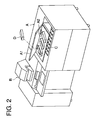
- Fig. 2 is a perspective view of the above-mentioned light-sensitive processing apparatus.
- Fig. 3 is a cross-section view of the automatic processing machine of the present invention.
- Fig. 4 is a schematic view showing a comparative example of a color developing tank of Example 1.
- Fig. 5 is a schematic view showing the color developing tank of Example 1.
- Fig. 6 is a cross-section view of a granule processing agent supplying apparatus of the example of a variation of Example 1.
- Fig. 7 is a schematic view showing a color developing tank of Example 2.
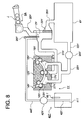
- Fig. 8 is a schematic view showing a color developing tank of Example 3.
- Fig. 9(A) through 9(C) are diagrams of a color developing tank of Example 3.
- Fig. 10(A) and 10(B) are diagrams of a color developing tank of Example 4.
- Fig. 11 is a schematic view showing a color developing tank of Example 5.
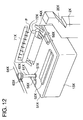
- Fig. 12 is a perspective view showing a color developing tank of Example 5.
- Fig. 13 is a cross-sectional view showing a color developing tank of Example 5.
- Fig. 14 is a perspective view showing when a lid member of a color developing tank of Example 5 is opened.
- Fig. 15 is a side cross-sectional view of the automatic processing machine of Example 6.
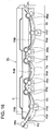
- Fig. 16 is a side cross-sectional view from the color developing tank to the first stabilizing processing tank of the automatic processing machine of Example 6.
- Fig. 17(a) is a top view
- Fig. 17(b) is a side cross-sectional view of the color developing tank of Example 6
- Fig. 17(c) is a schematic view of an auxiliary tank.
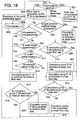
- Fig. 18 is a control flow chart showing a control flow of the circulation of the processing solution in the processing tank of the automatic processing machine for Example 6.
- FIG. 1 is a schematic block diagram of a silver halide photographic light-sensitive processing apparatus (printer processor) wherein an automatic processing machine A and a photographic printer are integrally structured.
- a magazine M housing the roll of photographic paper which is an unexposed silver halide photographic light-sensitive material is set.
- Photographic paper fed from the magazine M is cut to a prescribed size through a feeding roller R1 and a cutter unit C1 to form sheets of photographic paper.
- This photographic paper is conveyed by means of a belt conveyance means Be.
- an exposure unit E an image of the original picture O is exposed by means of a light-source and a lens L.
- the exposed sheet type photographic paper is conveyed by means of rollers R2, R3 and R4 which are respectively composed of pairs of rollers and introduced to the automatic processing machine A.
- the sheet type photographic paper is conveyed through a color developing tank 1A, a bleach-fixing processing tank 1B and a stabilizing processing tank (the first stabilizing processing tank 1C, the second stabilizing processing tank 1D and the third stabilizing processing tank 1E, which is a processing tank 1T substantially composed of three tanks) which are processing tanks fed by a roller conveyance means (having no reference number) sequentially, and thereby the photographic paper is subjected to color developing processing, bleach-fixing processing and stabilizing processing.
- the sheet type photographic paper, subjected to each of the above-mentioned processing is dried at the drier unit 5 and then exits outside the machine.
- the present invention is however not limited thereto. It can be applied to any automatic processing machine substantially composed of 4 tanks including the color developing tank, the bleaching processing tank, the fixing processing tank and the stabilizing processing tank.
- Air of high temperature (about 55 to 65°C) and high humidity emitted from the drier unit 5 is chilled, through a filter 95T, in a chilling apparatus 91T.
- the chilled air is dehumidified in a dehumidifier 92T.
- the dehumidified air is heated in a heater 93T, and then, supplied to the drier unit 5 as dry air. In this manner, dry air circulates.
- Water condensed in the dehumidifier 92T is supplied to replenishing water tank 41T through a water-feeding tube 94T.
- one-dot chain line in the Figure shows the conveyance route of a silver halide photographic light-sensitive material.
- the light-sensitive material can be introduced to the automatic processing machine A as a cut sheet.
- the light-sensitive material introduced to the automatic processing machine in a strips state is also allowed. In such situations, when an accumulator is provided for keeping the light-sensitive material temporarily is provided between the automatic processing machine A and the photographic printer B, processing efficiency is enhanced.
- the automatic processing machine A may be structured integrally with a photographic printer B or may also be the automatic processing machine A as a single unit.
- the silver halide photographic light-sensitive material processed by the automatic processing machine A of the present invention is not limited to a photographic exposed paper. It includes also an exposed negative film.
- the one-dot chain line in Fig. 1 shows the conveyance route of the silver halide photographic light-sensitive material.
- the light-sensitive material is fed to the automatic processing machine A in a cut state.
- the light-sensitive material may be fed to the automatic processing machine in a roll state. In this occasion, processing efficiency is improved if an accumulator which temporarily stores the light-sensitive material between the automatic processing machine A and the photographic printer B.
- the automatic processing machine A of the present invention may be structured integrally with the photographic printer B or it may be used independently.
- the silver halide photographic light-sensitive material processed by the automatic processing machine of the present invention is not limited to an exposed photographic paper but includes an exposed negative film.
- solid processing agent supplying means 3A, 3B and 3E respectively supplying a solid processing agent
- Fig. 2 is a perspective view showing an overall light-sensitive processing machine wherein the automatic processing machine A and the photographic printer B of the example of the present invention is integrally joined.
- a lid A1 of the automatic processing machine A is opened, and then, a housing D containing the solid processing agent is inserted from the upper left portion of the figure to the lower right portion and secured.
- Fig. 3 is a cross-sectional of an auxiliary tank which is a processing tank and the solid processing agent supplying means at I-I cross section in Fig. 1, of the automatic processing machine A.
- the stabilizing processing tanks (the first stabilizing processing tank 1C, the second stabilizing processing tank 1D and the third stabilizing processing tank 1E) have the same structure as the bleach-fixing processing tank 1B. Therefore, hereunder, when a processing tank 1T is referred to, both the bleach-fixing processing tank 1B and the stabilizing processing tanks (the first stabilizing processing tank 1C, the second stabilizing processing tank 1D and the third stabilizing processing tank 1E) shall be referred.
- the color developing tank is shown in Figs. 4 and 5. In Fig.
- the conveyance means which conveys the light-sensitive material is omitted.
- a tablet agent is used for the solid processing agent.
- the processing tank 1T which processes the light-sensitive material has an auxiliary tank 2T integrally provided outside a partition wall which forms aforesaid processing tank 1.
- the tablet agent J supplied from the solid processing agent supplying means 3A, 3B and 3E, passes through a solid processing agent supplying section 20T and is supplied to the auxiliary tank 2T.
- the above-mentioned 1T and the auxiliary 2T are partitioned by a partition wall 21A wherein a communication window 21T is formed so that the processing solution can be circulated.
- a replaceable cylindrical filter 22T is provided in the auxiliary tank 2T. It functions to remove insolubles such as coagulation in the processing solution.
- the center of this filter 22T is communicated with the absorption side of a circulation pump 24T through a circulation pipe 23T which penetrates the lower wall of the auxiliary tank 2T.
- the circulation system is structured by the auxiliary tank 2T, the circulation pipe 23T, the circulation pump 24T and a circulation pipe 25T, which form a circulation route of the solution and the processing tank 1T.
- the circulation direction of the processing solution is not necessary to be limited to a direction illustrated in Fig. 3, but may also be in the opposite direction.
- a bar heater 26T is provided in a manner that it penetrates the upper wall of the auxiliary tank 2T and is immersed in a processing solution inside the auxiliary tank 2T.
- This heater 26T heats the processing solution in the circulation route of the processing solution and a color developing tank 1N based on temperature sensed by a thermometer provided inside the auxiliary tank 2T but not illustrated.
- the heat 26T is a temperature regulating means which keeps the processing solution inside the processing tank 1T to temperature range suitable for processing (for example. 20 to 55°C).
- the color developing tank 1N which processes the light-sensitive material has an auxiliary tank 2N integrally provided outside a partition wall which forms aforesaid color developing tank 1N.
- a solid processing agent supplying chute 20N is provided over the auxiliary tank 2N.
- the tablet agent J supplied from the solid processing agent supplying means 3A passes through the solid processing agent supplying chute 20N and is fed to the auxiliary tank 2N.
- the above-mentioned color developing tank 1N and the auxiliary tank 2N are separated by a partition wall 21A wherein a communication window is formed so that the color developing solution can be circulated.
- a replaceable cylindrical filter 22N is provided in the auxiliary tank 2N. Its function is to remove insoluble matter such as coagulation in the color developing solution.
- the center of this filter 22N is communicated with the in-feed side of a circulation pump 24N (a circulation means) through a circulation pipe 23N which penetrates the lower wall of the auxiliary tank 2N.
- the above-mentioned circulation system is composed of the circulation route of the color developer solution formed by the auxiliary tank 2N, the circulation pipe 23N, the circulation pump 24N and a circulation pipe 25N, and the color developing tank 1N.
- the other end of the circulation pipe 25N which communicates with the out-feed side of the above-mentioned circulation pump 24N, penetrates the lower wall of the color developing tank 1N. Due to the above-mentioned structure, when the circulation pump operates, the color developing solution is pumped from the auxiliary tank 2N and emitted to the color developing tank 1N. The color developing solution is mixed with the color developing solution inside the color developing tank 1N, and then, fed to the auxiliary tank 2N again. Thus, the circulation is repeated.
- a bar heater 26N is provided in such a manner that it penetrates the upper wall of the auxiliary tank 2N and is immersed in the processing solution inside the auxiliary tank 2N.
- This heater 26N warms the processing solution in the circulation route of the processing solution and the color developing tank 1N based on temperature sensed by a thermostat housed inside the auxiliary tank 2N (not illustrated).
- the heater 26N is a temperature regulating means which keeps the processing solution inside the processing tank 1N in a temperature range suitable for processing (for example, 20 to 55°C).
- An effluent pipe 11N is provided for overflow of the color developing solution inside the color developing tank 1N. It is used for keeping the level of livid surface and is also used to remove excess components from the light-sensitive material and to be prevented from increasing.
- the color developing tank 1V which processes the light-sensitive material has an auxiliary tank 2V integrally provided outside a partition wall which forms aforesaid color developing tank 1V.
- a solid processing agent supplying chute 20V is provided over the auxiliary tank 2V.
- the tablet agent J fed from a solid processing agent supplying means 3A passes through the solid processing agent supplying chute 20V and is supplied to the auxiliary tank 2V.
- the above-mentioned color developing tank 1V and the auxiliary tank 2V are separated by a partition wall 21A wherein a communication window is formed so that a color developing solution can be circulated.
- a replaceable flat filter 22V is housed in the auxiliary tank 2V in such a manner that it partitions auxiliary tank 2V and the above of the developing solution housing tank 4V. It functions to remove insoluble coagulation in the color developing solution.
- the lower portion of the developing solution housing tank 4V is connected to the in-feed side of the circulation pump 24V (a circulation means) through the circulation pipe 23V which penetrates a lower wall near the bottom of the developing solution housing tank 4V.
- the above-mentioned circulation system is structured by the circulation route of the color developer solution formed by the auxiliary tank 2V, the developing solution housing tank 4V, the circulation pipe 23V, the circulation pump 24V and a circulation pipe 25V, and the color developing tank 1V.
- the other end of the circulation pipe 25V which is connected to the out-feed side of the above-mentioned circulation pump 24V penetrates the bottom of the color developing tank 1V. Due to the above-mentioned structure, when the circulation pump operates, the color developing solution is pumped from the auxiliary tank 2V to the color developing tank 1V. The color developing solution is mixed with the color developing solution inside the color developing tank 1V, and then, inserted to the auxiliary tank 2V. Thus, the circulation is continuously repeated.
- An effluent pipe 11V is provided for the overflow of the color developing solution inside the color developing tank 1V. It is used for keeping the level of the livid surface and is also used to remove excess components to be effused from the light-sensitive material and to be prevented from increasing.
- a photo-electric sensor is provided at the inlet portion of the automatic processing machine A as shown in Fig. 1 for sensing the processing amount of the light-sensitive material already processed.
- This sensing means for information about processing amount 31T, is provided with plural sensing members to the left and right directions. This functions as an element for counting time sense as well as sensing the width of the light-sensitive material. Since the conveyance speed of the light-sensitive material is mechanically set in advance, the processed area of the light-sensitive material can be calculated from the additional information of width and time.
- any system such as an infrared sensor, a micro switch and a supersonic sensor can be used for this sensing means for information about processing amount 31T provided that it can sense the width and conveyance time of the light-sensitive material such as an infrared sensor, a micro switch and a supersonic sensor.
- one which can sense processing area of the light-sensitive material indirectly such as one, in the case of a printer processor shown in Fig. 1, which senses the amount of light-sensitive material printed or senses the number of light-sensitive material processed having a predetermined area.
- time sensing is before being processed in the present invention. However, timing after being processed and during being immersion in the processing solution are also possible.
- a position to provide the sensing means for information about processing amount 31T may be changed to a position where the information can be sensed after being processed or where the information can be sensed during processing.
- a solid processing agent supplying means 32T Upon receiving a signal from the above-mentioned sensing means, for which provides information about the processing amount 31T, a solid processing agent supplying means 32T controls the supply of the processing agent from a solid processing agent supplying means 30T and also controls the supply of replenishing water through a replenishing water supplying means 40T.
- a solid processing agent supplying means 30T is provided above the processing tank 1T of the light-sensitive material processing apparatus which processes a light-sensitive material exposed.
- the solid processing agent supplying means 30T is composed of a housing container loading means 34T which loads a housing container D, a solid processing agent supplying means main body 35T which supplies the solid processing agent from the housing container D loaded in the housing container loading means 34T by a prescribed amount and a driving means 36T which drives the solid processing agent supplying means main body 35T, and closed by means of an upper cover 301T tightly.
- the upper cover 301T is bound by a main body 101T which houses the above-mentioned processing tank 1T and the auxiliary tank 2T and a supporting axis 302T so that aforesaid upper cover 301T can inspect a solid processing agent replenishing device 30T and replace the above-mentioned filter 22T by opening the front and the top from an operator side by being lifted to a direction of a dashed line A as illustrated.
- a cover 303T as part of the top of the upper cover 301T, is hinged oscilatedly so that aforesaid cover 303T can be opened in the direction of the dashed line B, as illustrated, for loading and replacing the above-mentioned housing container 33T.
- a replenishing water supplying means 40T is provided in the vicinity of replenishing tank 2N, 2V and 2T.
- the replenishing water supplying means 40T is structured by a replenishing water tank 41T, a bellows pump 42T, a water-in-feed tube 43T, a water feeding tube 44T and a replenishing water heating means 45T.
- Replenishing water W housed in the replenishing water tank 41T is kept heated to a prescribed temperature by means of the replenishing water heating means 45T.
- a developing agent CD-3 i.e. 4-amino-3-methyl-N-ethyl-N-[ ⁇ -(methanesulfonamido)ethyl]aniline sulfate was crushed to until an average grain size of 10 ⁇ m.
- a polyethylene glycol whose average molecular weight by weight was added. The resulting mixture was mixed uniformly in a commercially available mixer.
- Granulated products obtained by Procedures (11) and (12) were mixed in the same manner as in Procedure (4).
- 1000.0 g of polyethylene glycol whose average molecular weight by weight is 40,000 and 97.0 g of sodium N-lauroyl sulcosine were added, and then, mixed in a room at 25°C and 40%RH or less.
- the resulting mixture was subjected to a rotary tableting machine (Tough Press Collect H18 produced by Kikusui Seisakusho) so that a solid processing agent tablet for bleach-fixing for color paper wherein the diameter is 30 mm and the weight is 11.0 g was prepared.
- Processing step Processing temperature Processing time
- Replenishing amount of solid processing agent Added amount of replenishing water Color developing 42.0 ⁇ 0.2°C 10 seconds 7.8 g/m2 65 ml/m2 Bleach-fixing 38.0 ⁇ 0.5°C 10 seconds 6.2 g/m2 80 ml/m2 First stabilizing 38.0 ⁇ 3.0°C 8 seconds --- --- Second stabilizing 38.0 ⁇ 3.0°C 8 seconds --- --- Third stabilizing 38.0 ⁇ 3.0°C 8 seconds 1.0 g/m2 180 ml/m2 Drying 72.0 ⁇ 5.0°C 25 seconds --- --- (Note)
- the replenishing amount of solid processing amount is that per 1 m2 of photographic paper.
- the stabilizing processing tanks employed a counter-flow system wherein a solution flows from the third stabilizing processing tank to the first stabilizing processing tank.
- 80 ml/m2 flows into a bleach-fixing processing tank as replenishing water.
- Tablets were set into a tablet supplying device provided for the automatic processing machine.
- the supplied amount per time was 1 tablet (10.5 g) for color developing, 2 tablets (22.0 g) for bleach-fixing and 1 tablet (10.5 g) for stabilizing.
- the supplying interval was adjusted until the replenishing amount of solid processing agent resulted in the above-mentioned values.
- replenishing water was also replenished.
- the amount of replenishing water per time was adjusted in combination with the above-mentioned supplying of solid processing agents. Under the above-mentioned conditions, processing was conducted. In addition, with regard to the initial solution of each processing tank of the automatic processing machine, those regulated by the following formulas were used.
- a replenishing solution having the same ratio between the replenishing amount of solid processing agent and the added amount of replenishing solution as shown in the above-mentioned processing step was prepared.
- a light-sensitive material was processed by the use of the above-mentioned comparative replenishing solution in an automatic processing machine Nice Print System NPS 818 (produced by Konica) employing a conventional replenishing solution replenishing system wherein the structure is not modified to that shown in the above-mentioned Fig. 1.
- the replenishing amount of each processing solution was regulated to be the total amount of the supplying amount of solid processing agent shown in the processing step and the added amount of replenishing water to be processed (in Table 1, this system is referred to as "a conventional replenishing solution system").
- a light-sensitive material was subjected to running processing wherein a considerable amount of water was added as occasion called for off-set for the evaporation amount of each processing tank in accordance with the above-mentioned processing step by the use of a color developing tank shown in Fig. 4 and that shown in Fig. 5.
- the running processing was conducted for 12 hours which is a useal working durations of the automatic processing machine and continued for 2 weeks wherein 2.5 m2 of color paper was continuously processed per day.
- Dmin (Y) The minimum reflection density (Dmin (Y)) was measured by means of a color analyzer TOPSCAN MODEL tc-1800mKII (produced by Tokyo Denshoku Co., Ltd.). The difference of Dmin (Y) after running processing and that at the initial solution stage was defined to be the degree of the occurrence of stain due to the running.
- FIG.6 is a cross-sectional view showing a solid processing supplying device other than the present Example.
- a supplying device 80 supplies a granulated chemical by means of exiting portion 84 wherein a package 81 containing a granule processing agent was attached (loaded), the package was automatically opened by means of a roller 83 and the rotations of screw 82 was controlled.
- the present example employed a color developing tank shown in Fig. 7 in place of the color developing tank shown in Fig. 5 in Example 1.
- the structure of the color developing tank shown in Fig. 7 will be explained hereunder.
- a color developing tank 1W which processes a light-sensitive material, is composed of a lower member 13W which regulates the form of the lower half of the processing tank which goes along the conveyance route and which serves as a conveyance guide for the silver halide photographic light-sensitive material, an upper member 12W which regulates the form of the lower side of a processing tank which goes along the conveyance route and which serves as a conveyance guide for the silver halide photographic light-sensitive material and conveyance rollers 16W, 17W and 18W which transport the silver halide photographic light-sensitive material on the conveyance route between the lower member 13W and the upper member 12W for conveying the silver halide photographic light-sensitive material.
- insertion port 14W and exiting port 15W which are defined between the lower member 13W and the upper member 12W, which forms gas/liquid interface for a color developing solution which is in the color developing tank 1W.
- a cross-over guide 28W which is provided at the dowm stream side of the conveyance route at the exiting port 15W in contact with the upper member 12W and a pair of cross-over rollers 72W which are paired rollers facing each other for conveying the silver halide photographic light-sensitive material along with the cross-over guide 28W are provided.
- an auxiliary tank 2W Beside the color developing tank 1W which processes the light-sensitive material, an auxiliary tank 2W, provided separately from the color developing tank 1W, is provided.
- a circulation pipe 21W which connects the color developing tank 1W and the lower portion of the auxiliary tank 2W is provided to allow the color developing solution to flow.
- a solid processing agent supplying unit 20W Above the auxiliary tank 2W, a solid processing agent supplying unit 20W is provided above the auxiliary tank 2W. Tablets J supplied from a solid processing agent supplying means 3A passes the solid processing agent supplying chute 20W, and are dropped into the auxiliary tank 2W.
- a bar heater 26W is provided in such a manner that it penetrates the upper wall of the auxiliary tank 2W and is immersed in the processing solution inside the auxiliary tank 2W.
- This heater 26W warms the processing solution in the circulation route of the processing solution and the color developing tank 1W based on temperature sensed by a thermostat housed inside the auxiliary tank 2W (not illustrated).
- the heater 26W is a temperature regulating means which keeps the processing solution inside the processing tank 1W in a temperature range suitable for processing (for example, 20 to 55°C).
- a replaceable flat filter 22W is housed in the auxiliary tank 2W in such a manner that it partitions the lower portion of auxiliary tank 2W and the circulation pipe 29W communicating with the above developing solution housing tank 4W. It functions to remove insoluble coagulations in the color developing solution.
- the circulation pipe 29W communicates with the lower portion of the auxiliary tank 2W and the upper portion of the developing solution housing tank 4W.
- the lower portion of the developing solution housing tank 4W is connected to the in-feed side of the circulation pump 24W (a circulation means) through the circulation pipe 23W which penetrates a wall near the bottom of the developing solution housing tank 4W.
- the above-mentioned circulation system is structured by the circulation route of the color developer solution formed by the circulation pipe 21W, the auxiliary tank 2W, the circulation pipe 29W, the developing solution housing tank 4W, the circulation pipe 23W, the circulation pump 24W and a circulation pipe 25W, and the color developing tank 1W.
- the other end of the circulation pipe 25W which is connected to the out-feed side of the above-mentioned circulation pump 24W penetrates the bottom of the color developing tank 1W. Due to the above-mentioned structure, when the circulation pump operates, the color developing solution is pumped from the auxiliary tank 2W to the color developing tank 1W. The color developing solution is mixed with the color developing solution inside the color developing tank 1W, and then, pumped to the auxiliary tank 2W. Thus, the circulation is continuously repeated.
- the volume Vw of the color developing solution housed in the color developing tank 1W which processes a light-sensitive material was 1 liter.
- the volume Vf of the color developing solution in the circulation route was 4 liters.
- the circulation flow rate Vc of the color developing solution which occurs due to circulation pump 24W was 10 liters/minute.
- the total flowing-in cross-sectional area Se at the flowing-in port 14 W of the processing solution which circulates in the photographic processing was 10 cm2.
- the aperture area ratio N was 8 cm2/liter.
- the present example employs a color developing tank shown in Figs. 8 and 9 in place of the color developing tank shown in Fig. 7 of Example 2.
- a color developing tank 1Y which processes the light-sensitive material is composed of a lower member 13Y which regulates the form of the lower half of the processing tank which follows the conveyance route and which serves as a conveyance guide for the silver halide photographic light-sensitive material, an upper member 12Y which regulates the form of the lower side of a processing tank which follows the conveyance route and which serves as a conveyance guide for the silver halide photographic light-sensitive material and conveyance rollers 16Y, 17Y and 18Y which drive the silver halide photographic light-sensitive material on the conveyance route between the lower member 13Y and the upper member 12Y for conveying the silver halide photographic light-sensitive material.
- a cross-over guide 28Y which is provided at a lower stream side of the conveyance route at the exiting port 15Y in contact with the upper member 12Y and a pair of cross-over rollers 29Y which are rollers facing each other for conveying the silver halide photographic light-sensitive material along with the cross-over guide 28Y are provided.
- an auxiliary tank 2Y Beside the color developing tank 1Y which processes the light-sensitive material, an auxiliary tank 2Y, provided separately from the color developing tank 1Y, is provided.
- a circulation pipe 21Y which connects the color developing tank 1Y and the lower portion of the auxiliary tank 2Y is provided to allow the color developing solution to flow.
- a solid processing agent supplying unit 20Y Above the auxiliary tank 2Y, a solid processing agent supplying unit 20Y is provided above the auxiliary tank 2Y. Tablets J supplied from a solid processing agent supplying means 3A pass down the solid processing agent supplying chute 20Y, and are supplied to the auxiliary tank 2Y.
- a bar heater 26Y is provided in a manner that it penetrates the upper wall of the auxiliary tank 2Y and is immersed in the processing solution inside the auxiliary tank 2Y.
- This heater 26Y warms the processing solution in the circulation route of the processing solution and in the color developing tank 1N based on the temperature sensed by a thermostat provided inside auxiliary tank 2Y but not illustrated.
- the heater 26Y is a temperature regulating means which keeps the processing solution inside the processing tank 1Y in a temperature range suitable for processing (for example. 20 to 55°C).
- a replaceable flat filter 22Y is housed in auxiliary tank 2Y in such a manner that it partitions the lower portion of auxiliary tank 2Y and the circulation pipe 29Y communicating with the above developing solution housing tank 4Y. It functions to remove insoluble coagulation in the color developing solution.
- the circulation pipe 29Y communicates with the lower portion of the auxiliary tank 2Y and the upper portion of the developing solution housing tank 4Y.
- the lower portion of the developing solution housing tank 4Y is connected to the in-feed side of the circulation pump 24Y (a circulation means) through the circulation pipe 23Y which penetrates a wall near the bottom of the developing solution housing tank 4Y.
- the above-mentioned circulation system is structured by the circulation route for the color developer solution formed by the auxiliary tank 2Y, the circulation pipe 29Y, the developing solution housing tank 4Y, the circulation pipe 23Y, circulation pump 24Y and circulation pipe 25Y, and the color developing tank 1Y.
- the other end of the circulation pipe 25Y which is connected to the out-feed side of the above-mentioned circulation pump 24Y penetrates the bottom of the color developing tank 1Y. Due to the above-mentioned structure, when the circulation pump operates, the color developing solution is pumped from the auxiliary tank 2Y to the color developing tank 1Y. The color developing solution is mixed with the color developing solution inside the color developing tank 1Y, and then, pumped to the auxiliary tank 2Y. Thus, the circulation is continuously repeated.
- the volume Vw of the color developing solution housed in the color developing tank 1Y which processes a light-sensitive material was 1 liter.
- the volume Vf of the color developing solution in the circulation route was 4.5 liters.
- the circulation flow rate Vc of the color developing solution which fed by circulation pump 24Y was 10 liters/minute.
- the total flowing-in cross-sectional area Se at the flowing-in port of the processing solution which circulates in the photographic processing was 8 cm2.
- the aperture area ratio N was 7 cm2/liter.
- Fig. 9 shows practical structure of the color developing tank 1Y.
- Fig. 9 (A) shows the upper member 12Y which defines the form of the upper half of the processing tank which follows the conveyance route of the color developing tank 1Y and serves as the conveyance guide of the silver halide photographic light-sensitive material and also shows the conveyance rollers 16Y, 17Y and 18Y which drive the silver halide photographic light-sensitive material in the conveyance route between the lower member 13Y and the upper member 12Y for conveyance.
- Fig. 9 (A) shows the upper member 12Y which defines the form of the upper half of the processing tank which follows the conveyance route of the color developing tank 1Y and serves as the conveyance guide of the silver halide photographic light-sensitive material and also shows the conveyance rollers 16Y, 17Y and 18Y which drive the silver halide photographic light-sensitive material in the conveyance route between the lower member 13Y and the upper member 12Y for conveyance.
- Fig. 9 (A) shows the upper member 12Y which defines the form of the upper half of the
- FIG. 9 (B) is a figure showing an example of the lower member 13Y which defines the form of the lower half of the processing tank which follows the conveyance route in the color developing tank 1Y and which also serves as the conveyance guide for the silver halide photographic light-sensitive material too in the color developing tank 1Y.
- Plural number of nozzles 27Y which emit the color developing solution uniformly in a transversal direction are provided in the transversal direction, and which are longer than the width of the light-sensitive material being conveyed.
- FIG 9 (C) is a figure showing an another example of the lower member 13Y which defines the form of the lower half of the processing tank which follows the conveyance route in the color developing tank 1Y and which also serves as the conveyance guide for the silver halide photographic light-sensitive material too in the color developing tank 1Y.
- the present example employs a color developing tank shown in Fig. 10 in place of the color developing tank shown in Fig. 8 and 9 (A) and (B).
- Fig. 10 shows a practical example of the color developing tank 1Y.
- Fig. 10 (A) shows a form of the color developing tank 1Y.
- Fig. 10 (A) shows location thereof viewing from the emitting direction of the nozzle 27Y.
- plural rows of nozzles are provided wherein the width of each row is wider than the width of light-sensitive material conveyed and the intervals thereof are uniform. These nozzles take right angle to the direction of conveying the light-sensitive material.
- nozzles 27Y are provided in equivalent intervals. In adjoining rows, nozzles are shifted by 1/2 pitch. As a whole, the nozzles are provided totteringly. Since these nozzles are provided alternately to the conveyance direction, development unevenness occurs rarely.
- These nozzles blow pressed processing solution from holes whose diameters are 1.5 to 2.0 mm at blowing angle of 90°.
- Fig. 11 is a schematic drawing of the color developing procesing tank in Fig. 11.
- Fig. 12 is a perspective view of the color developing procesing tank of the present example when the light-sensitive material is processed wherein a cross-over guid 28 is omitted for easy understanding.
- Fig. 13 is a cross-sectional of the color developing procesing tank of the present example.
- Fig. 14 is a perspective view when a lid member of the color developing tank of the present example is opened. Hereunder, only the color developing tank will be explained.
- a color developing tank 1X which processes a light-sensitive material is composed of a lower member 13X which regulates the form of the lower side of a processing tank which goes along the conveyance route and which serves as a conveyance guide for the silver halide photographic light-sensitive material, an upper member 12X which regulates the form of the lower side of a processing tank which goes along the conveyance route and which serves as a conveyance guide for the silver halide photographic light-sensitive material and conveyance rollers 16X, 17X and 18X which drives the silver halide photographic light-sensitive material on the conveyance route between the lower member 13Y and the upper member 12X for conveying the silver halide photographic light-sensitive material.
- an auxiliary tank 2X provided separately from the color developing tank 1X, is provided.
- a circulation pipe 21X which communicates the color developing tank 1X and the lower portion of the auxiliary tank 2X is formed so that the color developing solution flows.
- a solid processing agent supplying portion 20X is provided above the auxiliary tank 2X.
- a tablet J supplied from a solid processing agent supplying means 3A passes the solid processing agent supplying portion 20X, and is supplied to the auxiliary tank 2X.
- a bar heater 26X is provided in such a manner that it penetrates the upper wall of the auxiliary tank 2X and is immersed in the processing solution inside the auxiliary tank 2X.
- This heater 26X warms the processing solution in the circulation route of the processing solution and the color developing tank 1X based on temperature sensed by a thermostat housed inside the auxiliary tank 2X (not illustrated).
- the heater 26X is a temperature regulating means which keeps the processing solution inside the processing tank 1X in a temperature range suitable for processing (for example, 20 to 55°C).
- a replaceable flat filter 22X is housed in the auxiliary tank 2X in such a manner that it partitions auxiliary tank 2X and the above of the developing solution housing tank 4X. It functions to remove insoluble coagulation in the color developing solution.
- the lower portion of the developing solution housing tank 4X is connected to the in-feed side of the circulation pump 24X (a circulation means) through the circulation pipe 23X which penetrates a lower wall near the bottom of the developing solution housing tank 4X.
- the above-mentioned circulation system is structured by the circulation route of the color developer solution formed by the circulation pipe 21X, the auxiliary tank 2X, the circulation pipe 29X, the developing solution housing tank 4X, the circulation pipe 23X, the circulation pump 24X and a circulation pipe 25X, and the color developing tank 1X.
- the other end of the circulation pipe 25X which is connected to the out-feed side of the above-mentioned circulation pump 24X penetrates the bottom of the color developing tank 1X. Due to the above-mentioned structure, when the circulation pump operates, the color developing solution is pumped from the auxiliary tank 2X to the color developing tank 1X. The color developing solution is mixed with the color developing solution inside the color developing tank 1X, and then, inserted to the auxiliary tank 2X. Thus, the circulation is continuously repeated.
- the volume Vw of the color developing solution housed in the color developing tank 1X which processes a light-sensitive material was 1 liter.
- the volume Vf of the color developing solution in the circulation route was 4 liters.
- the circulation flow rate Vc of the color developing solution which occurs due to circulation pump 24W was 10 liters/minute.
- the total flowing-in cross-sectional area St at the flowing-in port of the processing solution which circulates in the photographic processing was 10 cm2.
- the aperture area ratio N was 8 cm2/liter.
- a lid member 50X is provided above a color developing tank 1X.
- the lid member 50X is composed of a lid member main body, a packing member 53X and a movable shutting member 52X.
- the lid member main body 51X completely covers the color developing tank 1X so that a color developing solution inside the color developing tank 1X is completely shut from outer air substantially.
- an insertion port 55X and an exiting port 56X are provided, at positions each corresponding to the insertion port 14X and the exiting port 15X, which constitute a part of the conveyance route of the silver halide photographic light-sensitive material.
- a receiver 54X for receiving replenisher water supplied to a cross-over roller 72X and for supplying the replenisher water from the exiting port 56X to the color developing tank 1X is provided.
- a packing member 53X is provided at the entire bottom surface of the lid member main body 51X including a portion where the lid member 50 andthe upper portion of the color developing tank 1X.
- a driving transferring hole 57 for a driving transferring member 61X which transfers driving force to the conveyance roller 16X, 17X and 18X.
- the lid member 50X is fixed with a buckle 58X provided in the color developing tank 1X.
- a replenisher water supplying means 40T is provided near the above-mentioned auxiliary tank 2X.
- Aforesaid replenisher water supplying means 40T is composed of a replenisher water tank 41T, a bellows pump 42T, an in-feed pipe 43T and an out-feed pipe 44T.
- Replenisher water W housed in the replenisher tank 41T is in-fed through the in-feed pipe 43T due to the in-feeding effect of the bellows pump 42T.
- the replenisher water W due to the extrusion effect of the bellows pump, passes through the out-feed pipe 44T to be supplied above the processing solution liquid inside the auxiliary tank 2T.
- the driving motor of the above-mentioned bellows pump 42T is subjected to timing control by means of the replenisher water supplying and controlling means 45T to be driven and rotated so that the replenisher water is replenished intermittently.
- the width of the cross-over roller 72X is larger than that of the silver halide photographic light-sensitive material.
- Replenisher water supplied from the feeding pipe 44T is supplied from the replenisher water supplying nozzle 71X to the cross-over roller 72X.
- This replenisher water nozzle 71X by the use of plural nozzle holes, blows replenisher water uniformly over the entire surface of the cross-over roller 72X for supplying.
- the cross-over roller 72X is controlled to be rotated.
- the receiver 54X receives replenisher water supplied to the cross-over roller 72X, and then, replenisher water is supplied to the color developing tank 1X from the exiting port 56X.
- the conveyance rollers 16X, 17X and 18X are driven by means of a driving member 61X which transfers a driving force to the conveyance roller 16X, 17X and 18X.
- a driving transfering member 61X transfers the driving force from a driving roller 64X through a gear 63X provided on a driving gear 64X and a gear 62X provided on the driving transfering member 61X.
- the effluent tube 11X is for overflowing the color devleoping solution from the auxiliary tank 2X. It keeps the liquid surface level constant and is also useful for storing components effluent from the light-sensitive material and to prevent its increase.
- Fig. 15 is a schematic cross-sectionview view which is a schematic diagram wherein the cross-section of the automatic processing machine is described in conveyance direction.
- Fig. 16 is a side cross sectional of the automatic processing machine of the present invention wherein the cross-sectional of the color developing tank P3 through the first stabilizing tank in the conveyance direction are shown.
- a color developing tank P3, a bleach-fixing tank P4 and the first stabilizing tank P5, the second stabilizing tank P6 and the third stabilizing tank P7, for stabilizing processing are located to the side direction from left along with the conveyance direction of the silver halide photographic light-sensitive material (a photographic paper) P2.
- a color developing solution P3A, a bleach-fixing solution P4A and stabilizing solutions P5A, P6A and P7A are filled.
- Conveyance route of the light-sensitive material P2 is shown by one-dot chain line.
- the light-sensitive material is conveyed by the conveyance roller from the inlet port side as shown in PR1 through PR14.
- the processing solution in each tank is filled to almost the same level PL.
- Each processing tank is covered with an upper member P3B in the color developing tank P3, an upper member P4B in the bleach-fixing tank P4, an upper member P5B in the first stabilizing tank P5, an upper member P6B in the second stabilizing tank P6 and an upper member P7B in the third stabilizing tank P7 so that each processing tank may not overflow due to the processing solution. Due to this, the aperture area is extremely reduced. In addition, tank volume is also reduced.
- the tank volume of the color developing tank P3 and the bleach-fixing tank P4 is respectively 1 liter, and that of the first stabilizing tank P5, the second stabilizing tank P6 and the third stabilizing tank P7 is respectively 0.8 liter.
- the above-mentioned upper members P4B, P5B, P6B and P7B define the form of the top of the processing tank which follow the conveyance route, and also serve as the conveyance guide of the silver halide photographic light-sensitive material. Above the above-mentioned upper members are covered with an opening/closing lid C which can be opened/closed.
- the automatic processing machine of the present example forms a liquid flow in the vertical direction to the conveyance route shown by a dashed line.
- Fig. 17 which is a figure showing the color developing tank P3 as an example of the processing tank.
- Fig. 17(a) shows the color developing tank P3 from the top, wherein an arrowed line shows the main liquid flow.
- the color developing solution fed from a feeding-out port P81 of a pump P15 which is a liquid flow forming means and a circulation means passes openings P811, P812, P813 and P814 to become energetically and flows to the left of the figure in a manner that the color developing solution is fed-in a feeding-in port P82, provided at the left edge of the color developing tank P3, which is connected to a pump P26 which is a circulation means.located outside the apparatus.
- the processing solution fed to the pump P26 is returned to the auxiliary tank P16 through a pipe.
- the processing solution returned to the auxiliary tank P16 is returned to the processing tank by a pump P15 through a filter P27 for filtering.
- the solid processing agent is supplied from a solid processing supplying means P17 to the auxiliary tank P16. Replenishing water is supplied from a replenisher water tank P19 to the auxiliary tank P16 by means of a pump P18.
- Fig. 17(b) shows a form of the cross-sectional of Fig. 17(a) at X-X.
- Two rectangles in the vicinity of the center of fig. 17(a) is, as is understood by by fig. 17(b), a lower side of the color developer tank P3 and an inner wall of the color developer tank P3 functioning as a conveyance guide controlling the conveyance of the light-sensitive material P2.
- the solution is sprayed from the side direction to the conveyance direction of the light-sensitive material P2 to the vertical direction to a paper surface through the above-mentioned openings P11 through P14 as shown in Fig. 17 (b).
- a feeding-in port P82 at the bottom of the processing tank is connected to the circulation pump P26 through a pipe.
- the circulation pump P26 is connected to the auxiliary tank P16 through a pipe.
- the auxiliary tank P16 is connected to the circulation pump P15 through a pipe.
- the circulation pump P15 is connected to the feeding-out port P81 of the processing tank.
- the circulation pump P26 and the circulation pump P15 are circulation pumps which circulate processing solutions continuously. Its flow rate is continuously variable between 1 to 10 liters/minute, and can be controlled.
- an overflow port is provided, whereby the overflow solution remains in the effluent tank.
- the circulation pump P15 is controlled due to the processing of the light-sensitive material and the supply of the solid processing agent to the auxiliary tank P16.
- the processing tank there is provided a sensor for the surface of the processing solution, whereby information about solution surface sensed is transferred to the controlling means.
- the circulation pump P26 is controlled based on information from the processing solution surface sensor about the solution surface of the surface of the processing solution in the processing tank and also based on the control amount to the circulation pump P15.
- the volume Vw of the color developing solution housed in the color developing tank P3 which processes a light-sensitive material was 1 liter.
- the volume Vf of the color developing solution in the circulation route was 4 liters.
- the circulation flow rate Vc of the color developing solution which occurs due to circulation pump P15 and P26 was 10 liters/minute.
- the total flowing-in cross-sectional area Se at the flowing-in port of the processing solution which circulates in the photographic processing (in this example, the total of the apertures P811, P812, P813 and P814) was 10 cm2.
- the aperture area ratio N was 8 cm2/liter.
- the auxiliary tank P16 has the same constitution as the auxiliary tank in Fig. 3 in Example 1, and it has a solid processing agent supplying means P17 in the same manner as in the auxiliary tank in Fig. 7 in Example 2.
- a temperature adjusting means composed of a heater P31 which is a warming means and a temperature sensing sensor, wherein temperature is adjusted to a prescribed temperature (in an experiment described later, 38 ⁇ 1°C).
- a solid processing agent supplying section 20W is provided above the auxiliary tank P16, whereby the tablet J supplied from the solid processing agent supplying means P17 is supplied to the auxiliary tank P16.
- a bar heater P32 is provided in such a manner that it penetrates the upper wall of the auxiliary tank P16 and is immersed in the processing solution inside the auxiliary tank P16.
- This heater P32 warms the processing solution in the circulation route of the processing solution and the color developing tank P5 based on temperature sensed by a thermostat housed inside the auxiliary tank P16 (not illustrated).
- the heater P32 is a temperature regulating means which keeps the processing solution inside the processing tank P5 in a temperature range suitable for processing (for example, 20 to 55°C).
- a replaceable flat filter P27 is housed in the auxiliary tank P16. It functions to remove insoluble coagulation in the color developing solution.
- Fig. 18 is a control flow of the circulation system of the present example.
- the circulation pump P26 and the circulation pump P15 are driven at a small flow rate.
- controllers in the automatic processing machine such as a controller for the temperature of processing solution, a controller for the conveyance of the light-sensitive material, a controller for the replenishing of the processing agent and a controller for water replenishing are driven. Up to this step, all processing tanks are controlled commonly. After this step is finished, control is conducted for each processing tank, and proceeds to Step S01 in Fig. 18.
- step S01 the height of the liquid surface sensed by a liquid surface sensor in the processing tank is determined.
- the flow continues to step S04.
- step S01 when the height of the liquid surface is lower than the prescribed range, advance to step S02, and reduce the flow rate of the circulation pump P26 by a prescribed ratio, and then, advance to step S04.
- step S01 when the height of the liquid surface is greater than the in prescribed range, advance to step S03, and increase the flow rate of the circulation pump P26 by a prescribed ratio, and then, advance to step S04.
- step S04 determine whether or not the light-sensitive material is being processed.
- advance to step S11 when the light-sensitive material is not being processing, advance to step S11.
- step S05 When the light-sensitive material is being processed, advance to step S05.
- step S06 determine whether or not the circulation pump P26 has already coped with increasing the flow rate.
- the circulation pump P26 has already produced an increased flow rate, return to step 01.
- advance to step S07 When the circulation pump P26 has not coped with increasing the flow rate yet, advance to step S07, and increase the flow rate of the circulation pump P26 to the prescribed flow rate and return to step S01.
- step S11 determines whether or not a time passed from the solid processing agent is supplied from the solid processing agent supplying means P17 in the auxiliary tank P16 (time by means of a timer which measures time passed from the solid processing agent was supplied from the solid processing agent supplying means finally) is less than a prescribed time. If the time of the timer is less than the prescribed time, advance to step S17, where cause the flow rate of the circulation pump P15 a prescribed middle flow rate, and then, advance to step P19. If the time of the timer is not less than the prescribed time, advance to step S12, where whether or not water is during replenished is judged.
- step S17 If water is during replenishing, advance to step S17, where cause the flow rate of the circulation pump P15 a prescribed middle flow rate, and then, advance to step P19. If water is not replenishing, advance to step P13, where judge whether or not the heater P32 in the auxiliary pump P16 is during heating. If the heater P32 in the auxiliary tank P16 is during heating, advance to step S17 and cause the flow rate of the circulation pump P15 to a prescribed middle flow rate, and then, advance to step S19. If the heater P32 in the auxiliary tank P16 is not during heating, advance to step S14 where determine whether or not a conveyance means which conveys a light-sensitive material in the processing tank operates.
- step S17 If the conveyance means operates, advance to step S17 where cause the flow rate of the circulation pump P15 to a middle flow rate, and then, advance to step S19. If the conveyance means do not operate, advance to step S15 where cause the flow rate of the circulation pump P15 to a prescribed middle flow rate, and then, advance to step S16.
- step S16 judge whether or not the circulation pump P26 has coped with the reduction of the flow rate. When the circulation pump P26 has already coped with the reduction of the flow rate, return to step S01. When the circulation pump P26 has not coped with the reduction of the flow rate, advance to step S18, where reduce the flow rate of the circulation pump P26, and then, return to step S01.
- step S19 judge whether or not the circulation pump P26 has already been switched to middle flow rate.
- the circulation pump P26 has already been switched to middle flow rate, return to Step S01.
- the circulation pump P26 has not been switched to middle flow rate, advance to Step S20, and then, switch the flow rate of the circulation pump P26 to a prescribed middle flow rate, and then, return to step S01.
- step 08 interruption processing is conducted to step 08, and then, advance to step S09.
- the passing time is set to "0" again (the timer is set to "0” again), and then, advance to step S17.
- replenishing water circulates in a large amount only when the light-sensitive material is processed so that contributing to increasing the speed of processing.
- the light-sensitive material is not processed, due to switching to a low flow rate or the middle flow rate, oxidation and deformation of the processing agent component which is caused by switching to a large flow rate are prevented.
- a problem of uneven processing due to the occurrence of a low density processing agent component solution and increase of the density of a processing solution because replenisher water is not mixed when water is replenished.
- the large flow rate was set to be 10 liters/minute
- the middle flow rate was set to be 5 liters/minute
- a low flow rate was set to be 1 liter/minute in advance respectively.
- the solid processing agent is supplied in a prescribed amount every time the processing amount of the light-sensitive material, sensed by a light-sensitive material processing amount sensing means provided, for sensing the processing amount of the light-sensitive material, at the inlet port of the automatic processing machine is the multiple amount of the prescribed processing amount of the light-sensitive material per one supply cycle.
- the processing amount of the light-sensitive material per supply cycle is calculated from a prescribed unit amount per supply cycle and the replenishing amount of the solid processing agent per 1 m2 of the light-sensitive material processed.
- the heater P32 in the auxiliary tank P16 is warmed at 100% of heater's capacity.
- the sensed temperature of a thermostat in the auxiliary tank P16 is (a prescribed temperature - a prescribed deviation temperature) or more and the prescribed temperature or less, the heater P32 in the auxiliary tank P16 is warmed at 95% of heater's capacity.
- the temperature is adjusted to be the prescribed temperature by switching off the heater P32 in the auxiliary tank P16.
- the sensed temperature of a thermostat in the auxiliary tank P16 is (a prescribed temperature - a prescribed danger deviation temperature) or less and (a prescribed temperature + a prescribed danger deviation temperature) or more, alarm display is shown so that processing is controlled to be prohibited.
- the prescribed danger deviation temperature is larger than the prescribed deviation temperature.
- the processing amount of the light-sensitive material per one supply cycle is calculated from a prescribed unit amount per one supply cycle and the replenishing amount of the solid processing agent per 1 m2 of the light-sensitive material processed.
- conveyance rollers PR2 through PR16 are driven at regular intervals so that any components coagulated on any conveyance roller should not be enlarged (preferably, 30 seconds per every 10 minutes). Due to this, when the silver halide photographic light-sensitive material is processed inside the processing tank, processing property is enhanced due to strong circulation flow. When a solid processing agent and replenishing water are supplied while the silver halide photographic light-sensitive material is not processed inside the processing tank, circulation flow in an extent that deterioration of the processing agent (specifically, deterioration of the developing agent) is not accelerated is caused. Therefore, it was confirmed that keeping of high processing property (especially, developing property) and reduction of the air oxidation of the processing solution could be simultaneously achieved.
- Vw Vf (liter) means a volume of the developing solution housed in the above-mentioned developing tank and Vf (liter) means a volume of the developing solution located in the above-mentioned circulation route
- Vw Vf (liter) means a volume of the developing solution located in the above-mentioned circulation route
- the flow rate of the processing solution in the photographic developing tank can be increased and the flow rate of the processing solution in the circulation route can be reduced. Accordingly, in the developing tank which develops the silver halide photographic light-sensitive material by immersing in the developing solution, improvement of development processability and reduction of air oxidation of the developing agent in the circulation route can be coexistence.
- nozzle rows which blow the developing solution to the light-sensitive surface of the silver halide photographic light-sensitive material conveyed along a prescribed conveyance route in the developing tank, each having several nozzles, wherein each adjoining nozzle rows are slid and by providing aforesaid nozzles horizontally to the conveyance surface of the silver halide photographic light-sensitive material and vertical to the conveyance direction, the occurrence of uneven developing in a parallel direction of a conveyance direction of the silver halide photographic light-sensitive material can be prevented.
- a lid member which constitutes a part of the conveyance route and which has an insertion port and an exit port interrupts substantially the developing solution from air outside, gas/liquid interface does not substantially exist other than the insertion port and the exit port. Therefore, the area of the gas/liquid interface of the developing solution housed in the developing tank can noticeably reduced so that oxidation of the developing agent can remarkably be inhibited.
Landscapes
- Physics & Mathematics (AREA)
- General Physics & Mathematics (AREA)
- Photographic Processing Devices Using Wet Methods (AREA)
- Silver Salt Photography Or Processing Solution Therefor (AREA)
- Photographic Developing Apparatuses (AREA)
Applications Claiming Priority (3)
| Application Number | Priority Date | Filing Date | Title |
|---|---|---|---|
| JP6302275A JPH08160588A (ja) | 1994-12-06 | 1994-12-06 | ハロゲン化銀写真感光材料用自動現像機 |
| JP30227594 | 1994-12-06 | ||
| JP302275/94 | 1994-12-06 |
Publications (2)
| Publication Number | Publication Date |
|---|---|
| EP0716343A1 true EP0716343A1 (fr) | 1996-06-12 |
| EP0716343B1 EP0716343B1 (fr) | 2003-06-04 |
Family
ID=17907050
Family Applications (1)
| Application Number | Title | Priority Date | Filing Date |
|---|---|---|---|
| EP95119229A Expired - Lifetime EP0716343B1 (fr) | 1994-12-06 | 1995-12-06 | Dispositif de traitement automatique pour matériau photographique à l'halogénure d'argent sensible à la lumière |
Country Status (4)
| Country | Link |
|---|---|
| US (1) | US5689751A (fr) |
| EP (1) | EP0716343B1 (fr) |
| JP (1) | JPH08160588A (fr) |
| DE (1) | DE69530966T2 (fr) |
Cited By (2)
| Publication number | Priority date | Publication date | Assignee | Title |
|---|---|---|---|---|
| EP1203987A1 (fr) * | 2000-11-03 | 2002-05-08 | Eastman Kodak Company | Traitement de matériau photographique |
| EP1205800A1 (fr) * | 2000-11-03 | 2002-05-15 | Eastman Kodak Company | Développement de matériau photographique |
Families Citing this family (7)
| Publication number | Priority date | Publication date | Assignee | Title |
|---|---|---|---|---|
| JP3753767B2 (ja) * | 1995-12-21 | 2006-03-08 | 富士写真フイルム株式会社 | 画像形成装置 |
| GB9721467D0 (en) * | 1997-10-09 | 1997-12-10 | Eastman Kodak Co | Processing photographic material |
| US6383727B1 (en) * | 2000-11-03 | 2002-05-07 | Eastman Kodak Company | Method and system for processing photographic material which includes water recovery from humid air for re-use in the processing |
| GB0026949D0 (en) * | 2000-11-03 | 2000-12-20 | Eastman Kodak Co | Processing photographic material |
| US6702485B2 (en) * | 2001-05-16 | 2004-03-09 | Fuji Photo Film Co., Ltd. | Photosensitive material processing apparatus and pleated cartridge filter |
| CN101035455A (zh) * | 2005-07-26 | 2007-09-12 | 三菱电机株式会社 | 手干燥装置 |
| US20070048724A1 (en) * | 2005-09-01 | 2007-03-01 | Microsoft Corporation | Extensible context-enabled software |
Citations (30)
| Publication number | Priority date | Publication date | Assignee | Title |
|---|---|---|---|---|
| GB725892A (en) | 1952-06-26 | 1955-03-09 | Kodak Ltd | Improvements in single powder photographic developers |
| GB729862A (en) | 1952-06-26 | 1955-05-11 | Kodak Ltd | Improvements in single powder photographic developers |
| GB1213808A (en) | 1966-12-28 | 1970-11-25 | Eastman Kodak Co | Photographic processing compositions |
| JPS5161837A (ja) | 1974-09-26 | 1976-05-28 | Beroneshi Fuiorentsuo | Shashinkankozairyoshoryojozai oyobi sonoseiho |
| JPS5288025A (en) | 1976-01-19 | 1977-07-22 | Ricoh Co Ltd | Solid developers composition for diazo light sensitive material |
| JPS54133332A (en) | 1978-04-07 | 1979-10-17 | Oriental Photo Ind Co Ltd | Preparation of powdered bleaching agent for photograph |
| JPS54155038A (en) | 1978-05-26 | 1979-12-06 | Oriental Photo Ind Co Ltd | Method of producing bleachhfixing liquid |
| JPS6281964U (fr) | 1985-11-08 | 1987-05-25 | ||
| DE3733861A1 (de) | 1986-10-09 | 1988-04-21 | Du Pont | Pulverisierter verpackter entwickler und herstellungsverfahren |
| JPS6384151U (fr) | 1986-11-20 | 1988-06-02 | ||
| JPS6397522U (fr) | 1986-12-12 | 1988-06-24 | ||
| JPS63105159U (fr) | 1986-12-26 | 1988-07-07 | ||
| JPS63137783U (fr) | 1987-02-27 | 1988-09-12 | ||
| JPS63195345U (fr) | 1987-05-30 | 1988-12-15 | ||
| JPS6485732A (en) | 1987-09-28 | 1989-03-30 | Unitika Ltd | Polyethylen naphthalate-based copolymer heat resistant bottle |
| JPH01292375A (ja) | 1988-05-20 | 1989-11-24 | Ricoh Co Ltd | トナーカートリッジ |
| JPH02109042A (ja) | 1988-09-03 | 1990-04-20 | Agfa Gevaert Ag | 粒状カラー写真現像剤及びその製造方法 |
| JPH02109043A (ja) | 1988-09-03 | 1990-04-20 | Agfa Gevaert Ag | 粒状カラー写真現像剤及びその製造法 |
| JPH0339735A (ja) | 1989-06-27 | 1991-02-20 | Agfa Gevaert Ag | 顆粒化された写真定着剤及びその製造法 |
| JPH0339739A (ja) | 1989-06-27 | 1991-02-20 | Agfa Gevaert Ag | 顆粒化されたカラー写真漂白剤及びその製法 |
| WO1991012567A1 (fr) * | 1990-02-14 | 1991-08-22 | Kodak Limited | Procede et appareil de traitement photographique |
| JPH0429136A (ja) | 1990-05-24 | 1992-01-31 | Konica Corp | 感光材料自動現像機の処理液供給方法 |
| JPH0437198A (ja) | 1990-06-01 | 1992-02-07 | O S Giken Kogyo:Yugen | 回路基板への電子部品の搭載装置及び搭載方法 |
| JPH0485533A (ja) | 1990-07-30 | 1992-03-18 | Konica Corp | 写真用処理剤の固形化方法 |
| JPH0485536A (ja) | 1990-07-30 | 1992-03-18 | Konica Corp | 包装された写真用固形処理剤 |
| JPH04172341A (ja) | 1990-11-05 | 1992-06-19 | Konica Corp | 写真用処理剤の固形化方法及び写真用処理剤 |
| JPH04264550A (ja) | 1991-02-20 | 1992-09-21 | Konica Corp | ハロゲン化銀カラー写真感光材料の処理方法 |
| EP0537365A1 (fr) * | 1991-05-01 | 1993-04-21 | Konica Corporation | Appareil de developpement automatique pour support photosensible a base d'halogenure d'argent |
| JPH05119454A (ja) | 1991-05-01 | 1993-05-18 | Konica Corp | ハロゲン化銀写真感光材料用自動現像機 |
| EP0623844A1 (fr) * | 1993-05-03 | 1994-11-09 | Eastman Kodak Company | Appareils de développement automatiques |
Family Cites Families (5)
| Publication number | Priority date | Publication date | Assignee | Title |
|---|---|---|---|---|
| GB1491196A (en) * | 1973-11-07 | 1977-11-09 | Agfa Gevaert | Method and apparatus for processing photographic silver halide material |
| US5043756A (en) * | 1988-08-31 | 1991-08-27 | Konica Corporation | Automatic developing apparatus for a photosensitive material |
| US5452045A (en) * | 1992-10-30 | 1995-09-19 | Konica Corporation | Apparatus for processing a light-sensitive silver halide photographic material |
| US5398094A (en) * | 1993-05-03 | 1995-03-14 | Eastman Kodak Company | Slot impingement for an automatic tray processor |
| US5436118A (en) * | 1994-03-31 | 1995-07-25 | Eastman Kodak Company | Method of processing silver halide photographic elements using a low volume thin tank processing system |
-
1994
- 1994-12-06 JP JP6302275A patent/JPH08160588A/ja active Pending
-
1995
- 1995-11-30 US US08/565,339 patent/US5689751A/en not_active Expired - Fee Related
- 1995-12-06 DE DE69530966T patent/DE69530966T2/de not_active Expired - Fee Related
- 1995-12-06 EP EP95119229A patent/EP0716343B1/fr not_active Expired - Lifetime
Patent Citations (30)
| Publication number | Priority date | Publication date | Assignee | Title |
|---|---|---|---|---|
| GB725892A (en) | 1952-06-26 | 1955-03-09 | Kodak Ltd | Improvements in single powder photographic developers |
| GB729862A (en) | 1952-06-26 | 1955-05-11 | Kodak Ltd | Improvements in single powder photographic developers |
| GB1213808A (en) | 1966-12-28 | 1970-11-25 | Eastman Kodak Co | Photographic processing compositions |
| JPS5161837A (ja) | 1974-09-26 | 1976-05-28 | Beroneshi Fuiorentsuo | Shashinkankozairyoshoryojozai oyobi sonoseiho |
| JPS5288025A (en) | 1976-01-19 | 1977-07-22 | Ricoh Co Ltd | Solid developers composition for diazo light sensitive material |
| JPS54133332A (en) | 1978-04-07 | 1979-10-17 | Oriental Photo Ind Co Ltd | Preparation of powdered bleaching agent for photograph |
| JPS54155038A (en) | 1978-05-26 | 1979-12-06 | Oriental Photo Ind Co Ltd | Method of producing bleachhfixing liquid |
| JPS6281964U (fr) | 1985-11-08 | 1987-05-25 | ||
| DE3733861A1 (de) | 1986-10-09 | 1988-04-21 | Du Pont | Pulverisierter verpackter entwickler und herstellungsverfahren |
| JPS6384151U (fr) | 1986-11-20 | 1988-06-02 | ||
| JPS6397522U (fr) | 1986-12-12 | 1988-06-24 | ||
| JPS63105159U (fr) | 1986-12-26 | 1988-07-07 | ||
| JPS63137783U (fr) | 1987-02-27 | 1988-09-12 | ||
| JPS63195345U (fr) | 1987-05-30 | 1988-12-15 | ||
| JPS6485732A (en) | 1987-09-28 | 1989-03-30 | Unitika Ltd | Polyethylen naphthalate-based copolymer heat resistant bottle |
| JPH01292375A (ja) | 1988-05-20 | 1989-11-24 | Ricoh Co Ltd | トナーカートリッジ |
| JPH02109042A (ja) | 1988-09-03 | 1990-04-20 | Agfa Gevaert Ag | 粒状カラー写真現像剤及びその製造方法 |
| JPH02109043A (ja) | 1988-09-03 | 1990-04-20 | Agfa Gevaert Ag | 粒状カラー写真現像剤及びその製造法 |
| JPH0339735A (ja) | 1989-06-27 | 1991-02-20 | Agfa Gevaert Ag | 顆粒化された写真定着剤及びその製造法 |
| JPH0339739A (ja) | 1989-06-27 | 1991-02-20 | Agfa Gevaert Ag | 顆粒化されたカラー写真漂白剤及びその製法 |
| WO1991012567A1 (fr) * | 1990-02-14 | 1991-08-22 | Kodak Limited | Procede et appareil de traitement photographique |
| JPH0429136A (ja) | 1990-05-24 | 1992-01-31 | Konica Corp | 感光材料自動現像機の処理液供給方法 |
| JPH0437198A (ja) | 1990-06-01 | 1992-02-07 | O S Giken Kogyo:Yugen | 回路基板への電子部品の搭載装置及び搭載方法 |
| JPH0485533A (ja) | 1990-07-30 | 1992-03-18 | Konica Corp | 写真用処理剤の固形化方法 |
| JPH0485536A (ja) | 1990-07-30 | 1992-03-18 | Konica Corp | 包装された写真用固形処理剤 |
| JPH04172341A (ja) | 1990-11-05 | 1992-06-19 | Konica Corp | 写真用処理剤の固形化方法及び写真用処理剤 |
| JPH04264550A (ja) | 1991-02-20 | 1992-09-21 | Konica Corp | ハロゲン化銀カラー写真感光材料の処理方法 |
| EP0537365A1 (fr) * | 1991-05-01 | 1993-04-21 | Konica Corporation | Appareil de developpement automatique pour support photosensible a base d'halogenure d'argent |
| JPH05119454A (ja) | 1991-05-01 | 1993-05-18 | Konica Corp | ハロゲン化銀写真感光材料用自動現像機 |
| EP0623844A1 (fr) * | 1993-05-03 | 1994-11-09 | Eastman Kodak Company | Appareils de développement automatiques |
Cited By (3)
| Publication number | Priority date | Publication date | Assignee | Title |
|---|---|---|---|---|
| EP1203987A1 (fr) * | 2000-11-03 | 2002-05-08 | Eastman Kodak Company | Traitement de matériau photographique |
| EP1205800A1 (fr) * | 2000-11-03 | 2002-05-15 | Eastman Kodak Company | Développement de matériau photographique |
| US6620578B2 (en) | 2000-11-03 | 2003-09-16 | Eastman Kodak Company | Processing photographic material |
Also Published As
| Publication number | Publication date |
|---|---|
| DE69530966D1 (de) | 2003-07-10 |
| JPH08160588A (ja) | 1996-06-21 |
| DE69530966T2 (de) | 2004-05-19 |
| US5689751A (en) | 1997-11-18 |
| EP0716343B1 (fr) | 2003-06-04 |
Similar Documents
| Publication | Publication Date | Title |
|---|---|---|
| EP0424820B1 (fr) | Remplissage d'une solution de traitement | |
| EP0854386B1 (fr) | Appareil automatique pour le développement de matériaux photographiques à l'halogénure d'argent sensibles à la lumière | |
| EP0716343A1 (fr) | Dispositif de traitement automatique pour matériau photographique à l'halogénure d'argent sensible à la lumière | |
| EP0687953B1 (fr) | Appareil de développement automatique pour matériau photosensible à l'halogénure d'argent | |
| US5669035A (en) | Apparatus for processing a silver halide photosensitive material | |
| JP2001002225A (ja) | 固形写真薬品補充装置及び感光材料処理装置 | |
| JP3451508B2 (ja) | ハロゲン化銀カラー写真感光材料用自動現像機 | |
| JPH06110172A (ja) | 感光材料処理装置の補充液供給装置 | |
| JP3191195B2 (ja) | ハロゲン化銀写真感光材料用固体処理剤キット | |
| JPH086219A (ja) | ハロゲン化銀カラー写真感光材料の現像処理方法 | |
| US5587759A (en) | Automatic developing apparatus for silver halide photosensitive materials | |
| US5734946A (en) | Processing device for photographic materials | |
| JP3252245B2 (ja) | 感光材料処理用固体処理剤補充装置 | |
| JPH0764263A (ja) | ハロゲン化銀写真感光材料処理用自動現像機 | |
| JP3136383B2 (ja) | ハロゲン化銀写真感光材料用自動現像機 | |
| JP3282056B2 (ja) | ハロゲン化銀写真感光材料用自動現像機 | |
| JPH07295180A (ja) | ハロゲン化銀写真感光材料用自動現像機 | |
| JPH08211585A (ja) | ハロゲン化銀写真感光材料用固体処理剤補充装置、液体補充剤供給自動現像機を固体処理剤供給自動現像機に改造するユニット、及び該ユニットを搭載した自動現像機、及び自動現像機用フィルター固定部材 | |
| JP3335014B2 (ja) | 補充液補充装置 | |
| JPH07120891A (ja) | 固体処理剤容器 | |
| JPH09222709A (ja) | ハロゲン化銀カラー写真感光材料の処理方法及び自動現像処理装置 | |
| JPH0764246A (ja) | ハロゲン化銀写真感光材料用処理剤カートリッジ | |
| JPH02135341A (ja) | ハロゲン化銀カラー写真感光材料用の自動現像機 | |
| JPH07253647A (ja) | ハロゲン化銀写真感光材料用自動現像機 | |
| JP2002196462A (ja) | ハロゲン化銀写真感光材料用自動現像機 |
Legal Events
| Date | Code | Title | Description |
|---|---|---|---|
| PUAI | Public reference made under article 153(3) epc to a published international application that has entered the european phase |
Free format text: ORIGINAL CODE: 0009012 |
|
| 17P | Request for examination filed |
Effective date: 19960227 |
|
| AK | Designated contracting states |
Kind code of ref document: A1 Designated state(s): DE FR GB NL |
|
| 17Q | First examination report despatched |
Effective date: 20000918 |
|
| GRAH | Despatch of communication of intention to grant a patent |
Free format text: ORIGINAL CODE: EPIDOS IGRA |
|
| GRAH | Despatch of communication of intention to grant a patent |
Free format text: ORIGINAL CODE: EPIDOS IGRA |
|
| GRAA | (expected) grant |
Free format text: ORIGINAL CODE: 0009210 |
|
| AK | Designated contracting states |
Designated state(s): DE FR GB NL |
|
| PG25 | Lapsed in a contracting state [announced via postgrant information from national office to epo] |
Ref country code: NL Free format text: LAPSE BECAUSE OF FAILURE TO SUBMIT A TRANSLATION OF THE DESCRIPTION OR TO PAY THE FEE WITHIN THE PRESCRIBED TIME-LIMIT Effective date: 20030604 Ref country code: FR Free format text: LAPSE BECAUSE OF FAILURE TO SUBMIT A TRANSLATION OF THE DESCRIPTION OR TO PAY THE FEE WITHIN THE PRESCRIBED TIME-LIMIT Effective date: 20030604 |
|
| REG | Reference to a national code |
Ref country code: GB Ref legal event code: FG4D |
|
| REF | Corresponds to: |
Ref document number: 69530966 Country of ref document: DE Date of ref document: 20030710 Kind code of ref document: P |
|
| NLV1 | Nl: lapsed or annulled due to failure to fulfill the requirements of art. 29p and 29m of the patents act | ||
| PGFP | Annual fee paid to national office [announced via postgrant information from national office to epo] |
Ref country code: GB Payment date: 20031203 Year of fee payment: 9 |
|
| PLBE | No opposition filed within time limit |
Free format text: ORIGINAL CODE: 0009261 |
|
| STAA | Information on the status of an ep patent application or granted ep patent |
Free format text: STATUS: NO OPPOSITION FILED WITHIN TIME LIMIT |
|
| 26N | No opposition filed |
Effective date: 20040305 |
|
| EN | Fr: translation not filed | ||
| PGFP | Annual fee paid to national office [announced via postgrant information from national office to epo] |
Ref country code: DE Payment date: 20041202 Year of fee payment: 10 |
|
| PG25 | Lapsed in a contracting state [announced via postgrant information from national office to epo] |
Ref country code: GB Free format text: LAPSE BECAUSE OF NON-PAYMENT OF DUE FEES Effective date: 20041206 |
|
| GBPC | Gb: european patent ceased through non-payment of renewal fee |
Effective date: 20041206 |
|
| PG25 | Lapsed in a contracting state [announced via postgrant information from national office to epo] |
Ref country code: DE Free format text: LAPSE BECAUSE OF NON-PAYMENT OF DUE FEES Effective date: 20060701 |