EP0716412A2 - Elektrostatischer Schutz für einen abgeschirmten MR Sensor - Google Patents
Elektrostatischer Schutz für einen abgeschirmten MR Sensor Download PDFInfo
- Publication number
- EP0716412A2 EP0716412A2 EP95308828A EP95308828A EP0716412A2 EP 0716412 A2 EP0716412 A2 EP 0716412A2 EP 95308828 A EP95308828 A EP 95308828A EP 95308828 A EP95308828 A EP 95308828A EP 0716412 A2 EP0716412 A2 EP 0716412A2
- Authority
- EP
- European Patent Office
- Prior art keywords
- head
- read
- resistor
- high resistivity
- shield
- Prior art date
- Legal status (The legal status is an assumption and is not a legal conclusion. Google has not performed a legal analysis and makes no representation as to the accuracy of the status listed.)
- Withdrawn
Links
- 238000000034 method Methods 0.000 claims abstract description 11
- 239000000696 magnetic material Substances 0.000 claims abstract description 6
- 230000003068 static effect Effects 0.000 claims description 19
- 239000000463 material Substances 0.000 claims description 13
- PCHJSUWPFVWCPO-UHFFFAOYSA-N gold Chemical compound [Au] PCHJSUWPFVWCPO-UHFFFAOYSA-N 0.000 claims description 11
- 239000010931 gold Substances 0.000 claims description 11
- 229910052737 gold Inorganic materials 0.000 claims description 11
- 230000004907 flux Effects 0.000 claims description 9
- 239000002923 metal particle Substances 0.000 claims description 4
- 238000007599 discharging Methods 0.000 claims description 3
- UCHOFYCGAZVYGZ-UHFFFAOYSA-N gold lead Chemical compound [Au].[Pb] UCHOFYCGAZVYGZ-UHFFFAOYSA-N 0.000 claims description 2
- 230000008878 coupling Effects 0.000 claims 1
- 238000010168 coupling process Methods 0.000 claims 1
- 238000005859 coupling reaction Methods 0.000 claims 1
- 239000010409 thin film Substances 0.000 description 9
- 230000001965 increasing effect Effects 0.000 description 7
- 230000035945 sensitivity Effects 0.000 description 5
- 230000006872 improvement Effects 0.000 description 4
- 239000000758 substrate Substances 0.000 description 4
- 230000002463 transducing effect Effects 0.000 description 4
- 230000007704 transition Effects 0.000 description 4
- 238000010276 construction Methods 0.000 description 3
- 229910001030 Iron–nickel alloy Inorganic materials 0.000 description 2
- 230000008859 change Effects 0.000 description 2
- 230000000694 effects Effects 0.000 description 2
- 238000005516 engineering process Methods 0.000 description 2
- 230000007613 environmental effect Effects 0.000 description 2
- 239000010408 film Substances 0.000 description 2
- 230000001939 inductive effect Effects 0.000 description 2
- 230000005415 magnetization Effects 0.000 description 2
- 230000002441 reversible effect Effects 0.000 description 2
- 229910003321 CoFe Inorganic materials 0.000 description 1
- 229910003266 NiCo Inorganic materials 0.000 description 1
- WGLPBDUCMAPZCE-UHFFFAOYSA-N Trioxochromium Chemical compound O=[Cr](=O)=O WGLPBDUCMAPZCE-UHFFFAOYSA-N 0.000 description 1
- 229940035427 chromium oxide Drugs 0.000 description 1
- 229910000423 chromium oxide Inorganic materials 0.000 description 1
- 239000004020 conductor Substances 0.000 description 1
- 238000013500 data storage Methods 0.000 description 1
- 230000003247 decreasing effect Effects 0.000 description 1
- 238000010586 diagram Methods 0.000 description 1
- 238000006073 displacement reaction Methods 0.000 description 1
- 230000007774 longterm Effects 0.000 description 1
- 230000003287 optical effect Effects 0.000 description 1
- 238000000206 photolithography Methods 0.000 description 1
- 230000008569 process Effects 0.000 description 1
- 230000009467 reduction Effects 0.000 description 1
- 238000000926 separation method Methods 0.000 description 1
Images


Classifications
-
- G—PHYSICS
- G11—INFORMATION STORAGE
- G11B—INFORMATION STORAGE BASED ON RELATIVE MOVEMENT BETWEEN RECORD CARRIER AND TRANSDUCER
- G11B5/00—Recording by magnetisation or demagnetisation of a record carrier; Reproducing by magnetic means; Record carriers therefor
- G11B5/127—Structure or manufacture of heads, e.g. inductive
-
- G—PHYSICS
- G11—INFORMATION STORAGE
- G11B—INFORMATION STORAGE BASED ON RELATIVE MOVEMENT BETWEEN RECORD CARRIER AND TRANSDUCER
- G11B5/00—Recording by magnetisation or demagnetisation of a record carrier; Reproducing by magnetic means; Record carriers therefor
- G11B5/127—Structure or manufacture of heads, e.g. inductive
- G11B5/33—Structure or manufacture of flux-sensitive heads, i.e. for reproduction only; Combination of such heads with means for recording or erasing only
- G11B5/39—Structure or manufacture of flux-sensitive heads, i.e. for reproduction only; Combination of such heads with means for recording or erasing only using magneto-resistive devices or effects
- G11B5/3903—Structure or manufacture of flux-sensitive heads, i.e. for reproduction only; Combination of such heads with means for recording or erasing only using magneto-resistive devices or effects using magnetic thin film layers or their effects, the films being part of integrated structures
-
- G—PHYSICS
- G11—INFORMATION STORAGE
- G11B—INFORMATION STORAGE BASED ON RELATIVE MOVEMENT BETWEEN RECORD CARRIER AND TRANSDUCER
- G11B5/00—Recording by magnetisation or demagnetisation of a record carrier; Reproducing by magnetic means; Record carriers therefor
- G11B5/008—Recording on, or reproducing or erasing from, magnetic tapes, sheets, e.g. cards, or wires
- G11B5/00813—Recording on, or reproducing or erasing from, magnetic tapes, sheets, e.g. cards, or wires magnetic tapes
- G11B5/00817—Recording on, or reproducing or erasing from, magnetic tapes, sheets, e.g. cards, or wires magnetic tapes on longitudinal tracks only, e.g. for serpentine format recording
- G11B5/00821—Recording on, or reproducing or erasing from, magnetic tapes, sheets, e.g. cards, or wires magnetic tapes on longitudinal tracks only, e.g. for serpentine format recording using stationary heads
- G11B5/00826—Recording on, or reproducing or erasing from, magnetic tapes, sheets, e.g. cards, or wires magnetic tapes on longitudinal tracks only, e.g. for serpentine format recording using stationary heads comprising a plurality of single poles or gaps or groups thereof operative at the same time
-
- G—PHYSICS
- G11—INFORMATION STORAGE
- G11B—INFORMATION STORAGE BASED ON RELATIVE MOVEMENT BETWEEN RECORD CARRIER AND TRANSDUCER
- G11B5/00—Recording by magnetisation or demagnetisation of a record carrier; Reproducing by magnetic means; Record carriers therefor
- G11B5/10—Structure or manufacture of housings or shields for heads
- G11B5/11—Shielding of head against electric or magnetic fields
-
- G—PHYSICS
- G11—INFORMATION STORAGE
- G11B—INFORMATION STORAGE BASED ON RELATIVE MOVEMENT BETWEEN RECORD CARRIER AND TRANSDUCER
- G11B5/00—Recording by magnetisation or demagnetisation of a record carrier; Reproducing by magnetic means; Record carriers therefor
- G11B5/40—Protective measures on heads, e.g. against excessive temperature
Definitions
- the present invention relates generally to magnetic recording and more particularly, to a thin film magneto-resistive (MR) head having a protection from electrostatic discharge.
- MR magneto-resistive
- non-volatile storage media typically includes magnetic discs, magnetic tape cartridges, optical disk cartridges, floppy diskettes, or floptical diskettes.
- the advantages of storing data on non-volatile storage media are numerous, including: a capability of storing hundreds of megabytes or even gigabytes of data (additional cartridges can be used to store still more data); providing a vehicle for long term storage and archival; backing up that data which resides on non-removable media; and providing a convenient vehicle for transferring data between computers.
- magnetic tape media is the most economical means of storing or archiving the data.
- the amounts of data stored, accessed and processed by computers has increased as the computing power of the internal processors has increased.
- storage technology is continually pushed to increase storage capacities (as well as storage reliability). Improvements in storage densities in magnetic storage mediums, for example, has come in many areas including improved medium materials, improved error correction techniques, and decreased bit sizes.
- the amount of data stored on half inch magnetic tape for example, has increased from megabytes of data stored on nine data tracks to gigabytes of data stored on 128 tracks of data.
- the improvement in data densities on magnetic storage media is due in large part to improvements made in the transducer used for reading and writing data to the magnetic storage medium.
- a major improvement in transducer technology has been realized with the magneto-resistive (MR) transducer developed by the IBM corporation.
- the MR transducer detects magnetic field signals as resistance changes in an MR stripe.
- Data densities can be increased using an MR transducer because signal levels for the MR transducer are typically much higher than for conventional independent of media velocity or time rate of change of the sensed fields.
- Magnetic tape (and to some extent magnetic disks) is passed very near or directly over the MR transducer for reading data therefrom and writing data thereto.
- a buildup of static charge on the media if allowed, could cause single or double bit failures, or worst could damage the sensitive MR transducer, thereby unacceptably reducing reliability.
- low resistive magnetic tape media such as chromium-oxide magnetic tape, allowed static charge buildup to bleed off through the tape housing or at other points along the tape path.
- higher resistivity media for example, metal particle media, under certain atmospheric conditions, does not allow sufficient bleed off of static charge buildup.
- An object of the present invention is to provide an improved magneto-resistive head.
- Another object of the present invention is to provide a magneto-resistive head having electrostatic protection.
- Yet another object of the present invention is to provide a magneto-resistive head having electrostatic protection wherein the protection means is realized without additional processing steps.
- a magneto-resistive (MR) head including at least one write gap for providing magnetic flux signals and at least one corresponding MR read transducer for reading magnetic flux signals.
- At least one MR shield pair is provided for shielding the magnetic flux signals from the at least one MR read transducer until the magnetic flux signals are within a predetermined distance from the MR read transducer.
- a resistor is coupled between the at least one MR shield pair and a ground signal for discharging static charge buildup from the MR head.
- a method of reducing single and double bit errors due to static charge build-up and discharge at a magneto-resistive (MR) head due to a magnetic storage medium passing by the MR head wherein the MR head includes a plurality of MR read transducers and a corresponding plurality of write transducers.
- the method includes the steps of shielding each MR read transducer with first and second MR shields and providing a resistive path from each MR shield to a ground lead of each MR read transducer of the plurality of MR read transducers.
- the magnetic storage medium is passed by the MR head, and any static charge buildup on the MR head is shunted from each MR shield through the resistive path to ground.
- FIG. 1 is a schematic diagram of a tape drive and controller useful with the magnetic head according to the present invention.
- FIG. 2 is a top view of a length of magnetic tape and its relationship to an interleaved magnetic head.
- FIG. 3 is a sectional view of a portion of an interleaved head.
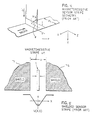
- FIG. 4 is a schematic representation of a prior art magneto-resistive sensor stripe geometry.
- FIG. 5 is a schematic representation of a prior art shielded magneto-resistive stripe.
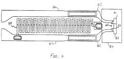
- FIG. 6 is a plan view of a shielded MR sensor having electrostatic discharge protection according to a preferred embodiment of the present invention.
- Interleaved magnetic tape heads are useful for reading and writing magnetic transitions from a multi-track recording medium as is well known in the art.
- a typical tape drive system is the IBM 3490 tape drive.
- the MR head may remain fixed while the tape is moved across the MR head in both directions to read and write from various transducers in the MR head for reading or recording data to one or more of a plurality of tracks on the tape.
- the MR head can be moved transversely to the tape for accessing a greater number of tracks on the tape than the number of transducers existing on the MR head.
- the interleaved MR head makes it possible to increase a number of tracks while providing bi-directional operation of the medium and simultaneous permitting an immediate read back check of data just written onto the medium (read after write). More tracks are made possible by reducing feature sizes of the read and write transducers. As the feature sizes are reduced, reading and writing accuracy becomes ever more sensitive to environmental conditions, including static charge buildup on the medium.
- FIG. 1 shows a controller 10 accepting information from a supply reel tachometer 12 which is connected to a supply reel motor 14.
- the supply reel motor 14 is driven by a motor drive circuit 23 to reversibly rotate a supply reel 16 shown within a single supply reel cartridge 16A.
- the tachometer 12 directs count pulses to a counter 19 to indicate the number of rotations and the rotational position of the motor 14 and hence the supply reel 16.
- the output of the counter 19 is directed to a control unit 17.
- Another input of the control unit 17 is via the counter 19 that accepts count pulses from a take up reel tachometer 20.
- the tachometer 20 is connected to a take up reel motor 22 that is reversibly driven by the motor drive 23 which applies torque under control of the control unit 17.
- the motor 22 drives a take up reel 24.
- a timer 26 is connected to the control unit 17 in the controller 10 to control the application of the motor drive 23 power to the motors 14 and 22.
- a magnetic tape 28 and its leader block takes a path, shown by dotted line 27, from the supply reel 16 to the take up reel 24 past an idler bearing 30, air bearing tape guides 32 and 34, and an MR head 36.
- the tape path 27 continues around a roller 38 of a tension arm transducer 18 to the take up reel 24.
- An output of the MR head 36 is connected to a read/write network 15.
- the read/write network 15, under control of the control unit 17, directs data to a data unit 13 in the read format, and accepts data from the data unit 13 when data is to be written onto the tape 28 by the MR head 36.
- the tape drive of FIG. 1 is generally of the 1/2 inch type having a single reel cartridge. As is well known in the tape drive industry, other media formats are also available, for example quarter inch cartridge (QIC), digital linear tape (DLT), digital analog tape (DAT), and video (19mm), etc.
- the MR head 36 can take the form of a number of well known construction types and arrangements. Thin film photolithography construction makes it possible to maximize use of the surface area of the magnetic tape, since narrow, closely placed tracks can be written. Transversely adjacent head elements are not operative at the same time, thus minimizing the possibility of cross-talk and the like.
- the write element is an inductive write element comprising two layers of magnetic material, driven by a thin film coil formed by standard photolithographic steps.
- the preferred read element is a magneto-resistive element.
- the MR read gaps are preferably of the soft film biased (SFB) type.
- the read elements are marked "R” for the MR head 36 while the write elements are marked “W".
- the read and write gaps are used in immediately alternating odd/even fashion.
- the term alternating is intended to include other formats.
- one format provides that the odd numbered tracks, tracks 1, 3, 5, and so on are operative during forward tape movement, while the even numbered tracks 2, 4, 6 and so on are operative during the opposite direction of tape movement.
- Other formats useable in the practice of the present invention will of course be evident to those skilled in the art, and are considered to be within the teaching of the present invention.
- the length of magnetic tape 28 moves in both a forward and a reverse direction as indicated by the arrows 40 and 42.
- the arrow 40 designates the forward movement of direction of the tape 28 and the arrow 42 designates the reverse direction.
- the magnetic tape 28 operates in transducing relationship with the MR head 36 in the standard well known format.
- the MR head 36 includes two modules 44 and 46 of generally identical construction. The modules 44 and 46 are mounted together to form a single physical unit. In this manner, the transducing gaps of one module are not only closely spaced to the transducing gaps of the other unit, but also, the module gaps are accurately aligned in the direction of tape movement.
- Each module 44, 46 includes one gap line 48, 50, respectively, to form the single physical unit of MR head 36.
- the individual gaps of each module 44, 46 are accurately located along the gap lines 48, 50.
- the gap lines 48, 50 are parallel and the MR head 36 is mounted in the tape drive (FIG. 1) such that the gap lines 48, 50 are perpendicular to the direction of tape movement as represented by arrows 40, 42.
- the MR head 36 includes the alternating read/write gaps along the length of each of the gap lines 48, 50 for each of the modules 44, 46.
- Magnetic tape 28, therefore, has at least thirty six tracks its one half inch width.
- the tracks are written approximately thirty five percent wider than the read gaps are able to read.
- the gaps of one module, module 44 cooperate with the identically numbered gaps of the module 46.
- gaps identified as “1” through “36” of module 44 cooperate with gaps identified as “1” through “36” of module 46.
- the read gaps of one module are aligned with the write gaps of the other module and vice versa.
- a write gap 52 of module 44 is aligned with a read gap 54 of module 46.
- Each of the modules 44, 46 include a substrate 56 and a closure piece 58.
- FIG. 3 depicts a portion of the thin film structure of the MR head 36.
- the module 46 is shown in a cut-away section with two thin film magneto-resistive read elements 60, 62 deposited onto the substrate 56.
- One thin film write coil 64 is shown positioned adjacent to the two MR read elements 60, 62.
- the transducing gap of the substrate 56 is shown at reference numeral 66.
- a back gap region 68 completes the magnetic circuit that is energized by the write coil 64.
- the closure 58 (not shown) is then affixed to the substrate 56.
- An MR shield enclosing the MR read transducers are described in detail below.
- FIG. 4 shows an MR read sensor strip geometry known in the art.
- the MR read sensor consists of a narrow strip of magneto-resistive materials such as NiFe, NiCo or CoFe, of height h and width Wt.
- the stripe is mounted in a plane perpendicular to the recording medium and connected to conductors at each end carrying a sense current Is. Because of the magneto-resistive effect, the resistivity of each portion of this stripe depends on the angle theta between the direction of magnetization Ms and the current density vector, as is well known in the art.
- the magnetization vector Ms represents the sum of a local bias field and the field from the recording medium. Because the device essentially responds to the average applied magnetic field, the resolution of an unshielded stripe is practically limited to stripe height h. This disadvantage is offset by the much higher output signal levels from the MR stripe when compared to conventional inductive heads.
- FIG. 5 shows the shielded MR stripe geometry known in the art.
- Two shields 71, 72 are disposed at a spacing (b) about the MR stripe 69, which is centred therebetween.
- Shields 71, 72 fabricated using a magnetic material, operate to prevent MR stripe 69 from experiencing the field in the recording medium until the recorded transition is within the gap width (b) of the MR stripe 69.
- the potential sensitivity function U(x,0) approximates the shape of the MR stripe 69 output responsive to the passage of a very narrow transition in a thin medium.
- the potential sensitivity function exhibits increased sensing resolution.
- Thin film techniques are widely used for fabricating MR sensors because of the advantageous effects of very narrow gap separations (b) and stripe heights (h). It is known that shielding MR stripe 69 on both sides improves sensing resolution by preventing the MR stripe 69 from experiencing the field from the medium until the recorded transition is very close. Where the edge of the MR stripe 69 is recessed from a face of the MR head 36, the potential sensitivity broadens slightly and degrades with the amount of recession. Lateral displacement of the MR stripe 69 toward one of the shields does not substantially diminish element sensitivity. Very thin shields tend to provide the relatively low resolution characteristic of unshielded MR stripes.
- Thin film shielded MR heads are susceptible to electrostatic discharge when used with certain types of media, for example, as discovered by the inventors of the instant invention, with high resistivity magnetic tape such as metal particle tape. Static charge buildup can occur due to debris adhering to the face of the MR head (e.g. triboelectric charging).
- the metal particle media does not provide a suitable path to ensure that the static charge can be dissipated via the tape housing or other points of contact to the magnetic tape.
- Environmental conditions such as low humidity can further exacerbate the problem.
- Electrostatic discharge typically results in a large narrow pulse being introduced into the data stream causing single and double bit errors. While error correction code (ECC) can be relied upon to correct most errors, the corresponding reduction in reliability is generally unacceptable.
- ECC error correction code
- FIG. 6 is a top plan view of a MR sensor 69 having electrostatic discharge protection according to a preferred embodiment of the present invention.
- the MR sensor 69 comprises a magnetic soft film bias (SFB) material 82, for example, NiFe/Ta/NiFeRh, sandwiched between two high resistivity permanent magnets 81, 83, for example, Cr/CoPtCr magnetic material.
- the MR sensor 69 has MR shields thereabove and therebelow (only MR shield 84 is shown since the bottom MR shield is directly below). Simply grounding the MR shields should assure that the MR sensor 69 does not accumulate charge thus avoiding the charging problem.
- the resistor 89 is defined with the same mask layer and is processed simultaneously therewith thereby avoiding additional processing requirements.
- vias contacting the resistor 89 to MR sensor shield 84 and to ground signal lead 87 are processed simultaneously as those vias processed for contacting the signal leads 86 and 87 to the elements 81, 83, respectively.
- the resistor 89 is typically several kilo-ohms and in the event that a short or pinhole occurs in the MR shield 82, results only in a negligible MR change. Therefore, the MR sensor 69 will continue to operate while being protected from electrostatic discharge.
- Leads 85 and 86 are thin gold leads connecting to signal leads 86 and 87 (thick gold leads) which continue to the lead attach.
- a magneto-resistive (MR) head having circuitry providing electrostatic protection for each MR read sensor.
- the MR head also includes least one write gap for each MR sensor.
- the MR head is fabricated such that no additional processing steps or photolithographic masks are required to provide effective electrostatic protection.
- An MR shield is located both above and below each MR sensor.
- First and second permanent magnets are located at first and second ends of MR read sensor and first and second thin gold leads are coupled to the first and second permanent magnets, respectively.
- First and second thick gold signal leads are coupled to the first and second thin gold leads respectively, the first and second thick gold leads being provided for contacting signal and ground terminals, respectively.
- a resistor comprising a same permanent magnet material as the first and second permanent magnets, is coupled between the first MR shield and the second thick gold lead, the resistor providing a path to ground for dissipating static charge buildup on the MR head.
Landscapes
- Engineering & Computer Science (AREA)
- Manufacturing & Machinery (AREA)
- Magnetic Heads (AREA)
Applications Claiming Priority (2)
| Application Number | Priority Date | Filing Date | Title |
|---|---|---|---|
| US354753 | 1994-12-08 | ||
| US08/354,753 US5539598A (en) | 1994-12-08 | 1994-12-08 | Electrostatic protection for a shielded MR sensor |
Publications (2)
| Publication Number | Publication Date |
|---|---|
| EP0716412A2 true EP0716412A2 (de) | 1996-06-12 |
| EP0716412A3 EP0716412A3 (de) | 1997-05-28 |
Family
ID=23394768
Family Applications (1)
| Application Number | Title | Priority Date | Filing Date |
|---|---|---|---|
| EP95308828A Withdrawn EP0716412A3 (de) | 1994-12-08 | 1995-12-06 | Elektrostatischer Schutz für einen abgeschirmten MR Sensor |
Country Status (4)
| Country | Link |
|---|---|
| US (1) | US5539598A (de) |
| EP (1) | EP0716412A3 (de) |
| JP (1) | JP3090602B2 (de) |
| KR (1) | KR100227955B1 (de) |
Cited By (1)
| Publication number | Priority date | Publication date | Assignee | Title |
|---|---|---|---|---|
| EP1376546A1 (de) * | 2002-06-21 | 2004-01-02 | O-Mass AS | Kopf in Kombination mit einem breiten Magnetband |
Families Citing this family (81)
| Publication number | Priority date | Publication date | Assignee | Title |
|---|---|---|---|---|
| US5820770A (en) * | 1992-07-21 | 1998-10-13 | Seagate Technology, Inc. | Thin film magnetic head including vias formed in alumina layer and process for making the same |
| US5326429A (en) * | 1992-07-21 | 1994-07-05 | Seagate Technology, Inc. | Process for making studless thin film magnetic head |
| US5761009A (en) * | 1995-06-07 | 1998-06-02 | International Business Machines Corporation | Having parastic shield for electrostatic discharge protection |
| US5748412A (en) * | 1995-08-11 | 1998-05-05 | Seagate Technology, Inc. | Method and apparatus for protecting magnetoresistive sensor element from electrostatic discharge |
| US5699212A (en) * | 1996-05-01 | 1997-12-16 | International Business Machines Corporation | Method of electrostatic discharge protection of magnetic heads in a magnetic storage system |
| US5777829A (en) * | 1996-10-08 | 1998-07-07 | International Business Machines Corporation | Method and apparatus for providing electrostatic discharge protection for an inductive coil of a magnetic transducer |
| JP3874875B2 (ja) * | 1997-02-24 | 2007-01-31 | 富士通株式会社 | 磁気ディスク装置 |
| JPH10247307A (ja) * | 1997-03-04 | 1998-09-14 | Fujitsu Ltd | 磁気ヘッド及び磁気記憶装置 |
| US5943196A (en) * | 1997-05-01 | 1999-08-24 | Storage Technology Corporation | Apparatus for securing a thin film magnetic tape head closure using a C-core to interconnect gluing vias |
| US5963401A (en) * | 1997-09-29 | 1999-10-05 | Storage Technology Corporation | Magnetic tape head assembly including modules having a plurality of magneto-resistive head elements |
| US20030042571A1 (en) * | 1997-10-23 | 2003-03-06 | Baoxing Chen | Chip-scale coils and isolators based thereon |
| US6054780A (en) * | 1997-10-23 | 2000-04-25 | Analog Devices, Inc. | Magnetically coupled signal isolator using a Faraday shielded MR or GMR receiving element |
| US6873065B2 (en) * | 1997-10-23 | 2005-03-29 | Analog Devices, Inc. | Non-optical signal isolator |
| US6067220A (en) * | 1998-04-02 | 2000-05-23 | Pemstar, Inc. | Shunt for protecting a hard file head |
| JP3923174B2 (ja) * | 1998-04-28 | 2007-05-30 | 富士通株式会社 | ヘッドアセンブリ及びサスペンション |
| US6085406A (en) | 1998-10-21 | 2000-07-11 | International Business Machines Corporation | Method of making a read head with improved lead layers at an air bearing surface |
| US6246553B1 (en) * | 1998-12-02 | 2001-06-12 | International Business Machines Corporation | Shielded magnetoresistive head with charge clamp |
| US6176005B1 (en) * | 1998-12-15 | 2001-01-23 | International Business Machines Corporation | Method of making read head with improved lead layers |
| US6583971B1 (en) * | 1999-03-09 | 2003-06-24 | Sae Magnetics (Hk) Ltd. | Elimination of electric-pop noise in MR/GMR device |
| US6424505B1 (en) * | 1999-05-06 | 2002-07-23 | Read-Rite Corporation | Method and system for providing electrostatic discharge protection for flex-on suspension, trace-suspension assembly, or cable-on suspension |
| JP4221114B2 (ja) | 1999-05-18 | 2009-02-12 | 株式会社日立グローバルストレージテクノロジーズ | 磁気抵抗効果型ヘッド |
| JP2001054536A (ja) | 1999-08-20 | 2001-02-27 | Uni Charm Corp | 模様シートを有する使い捨ておむつおよびその製造方法 |
| US6284107B1 (en) | 1999-11-03 | 2001-09-04 | Headway Technologies, Inc. | Method for controlling arcing across thin dielectric film |
| US6415500B1 (en) | 2000-01-13 | 2002-07-09 | Headway Technologies, Inc. | Method to prevent electrostatic discharge for MR/GMR wafer fabrication |
| US6262600B1 (en) * | 2000-02-14 | 2001-07-17 | Analog Devices, Inc. | Isolator for transmitting logic signals across an isolation barrier |
| US6653448B1 (en) | 2000-03-29 | 2003-11-25 | Curagen Corporation | Wnt-7B-like polypeptides and nucleic acids encoding same |
| US6453542B1 (en) | 2000-02-28 | 2002-09-24 | Headway Technologies, Inc. | Method for fabricating balanced shield connections for noise reduction in MR/GMR read heads |
| US6373660B1 (en) | 2000-03-14 | 2002-04-16 | Read-Rite Corporation | Method and system for providing a permanent shunt for a head gimbal assembly |
| US6687097B1 (en) | 2000-03-22 | 2004-02-03 | Pemstar, Inc. | Electrostatic protection for magnetic heads |
| JP2002100009A (ja) * | 2000-09-22 | 2002-04-05 | Mitsumi Electric Co Ltd | 磁気抵抗効果型磁気ヘッド |
| US6445538B1 (en) * | 2000-10-12 | 2002-09-03 | Storage Technology Corporation | Electrostatic discharge control in tape reading heads with conductive epoxy adhesive |
| US6470566B2 (en) | 2001-01-03 | 2002-10-29 | International Business Machines Corporation | ESD protection during GMR head fabrication |
| US6760199B2 (en) * | 2001-07-23 | 2004-07-06 | International Business Machines Corporation | Read/write head assembly employing independent read/write shield-pairing and charge-clamped magnetoresistive sensors |
| US6795278B2 (en) | 2002-03-28 | 2004-09-21 | International Business Machines Corporation | Method of protecting read sensors from electrostatic discharge damage during the manufacture of magnetic heads |
| US6732960B2 (en) * | 2002-07-03 | 2004-05-11 | Certainteed Corporation | System and method for blowing loose-fill insulation |
| US7369370B2 (en) | 2002-08-07 | 2008-05-06 | Headway Technologies, Inc. | GMR head design that suppresses tribocharge during its assembly |
| US6870706B1 (en) * | 2002-08-07 | 2005-03-22 | Headway Technologies, Inc. | Method for suppressing tribocharge in the assembly of magnetic heads |
| DE10243197B4 (de) | 2002-09-18 | 2011-05-05 | Infineon Technologies Ag | Digitales Signalübertragungsverfahren |
| US6987654B2 (en) * | 2002-11-27 | 2006-01-17 | Endevco Corporation | Electrostatic discharge circuit |
| WO2004100473A2 (en) * | 2003-04-30 | 2004-11-18 | Analog Devices, Inc. | Signal isolators using micro-transformers |
| US7505229B1 (en) * | 2004-01-08 | 2009-03-17 | Maxtor Corporation | Disk drive flex cable with ESD contact pad |
| US7302247B2 (en) | 2004-06-03 | 2007-11-27 | Silicon Laboratories Inc. | Spread spectrum isolator |
| US8169108B2 (en) * | 2004-06-03 | 2012-05-01 | Silicon Laboratories Inc. | Capacitive isolator |
| US8049573B2 (en) * | 2004-06-03 | 2011-11-01 | Silicon Laboratories Inc. | Bidirectional multiplexed RF isolator |
| US8441325B2 (en) | 2004-06-03 | 2013-05-14 | Silicon Laboratories Inc. | Isolator with complementary configurable memory |
| US7902627B2 (en) | 2004-06-03 | 2011-03-08 | Silicon Laboratories Inc. | Capacitive isolation circuitry with improved common mode detector |
| US7577223B2 (en) * | 2004-06-03 | 2009-08-18 | Silicon Laboratories Inc. | Multiplexed RF isolator circuit |
| US7821428B2 (en) * | 2004-06-03 | 2010-10-26 | Silicon Laboratories Inc. | MCU with integrated voltage isolator and integrated galvanically isolated asynchronous serial data link |
| US7447492B2 (en) | 2004-06-03 | 2008-11-04 | Silicon Laboratories Inc. | On chip transformer isolator |
| US7738568B2 (en) * | 2004-06-03 | 2010-06-15 | Silicon Laboratories Inc. | Multiplexed RF isolator |
| US8198951B2 (en) * | 2004-06-03 | 2012-06-12 | Silicon Laboratories Inc. | Capacitive isolation circuitry |
| US7460604B2 (en) | 2004-06-03 | 2008-12-02 | Silicon Laboratories Inc. | RF isolator for isolating voltage sensing and gate drivers |
| US7737871B2 (en) | 2004-06-03 | 2010-06-15 | Silicon Laboratories Inc. | MCU with integrated voltage isolator to provide a galvanic isolation between input and output |
| US20050281979A1 (en) * | 2004-06-17 | 2005-12-22 | Toas Murray S | Loose fill insulation product having phase change material therein |
| US8132382B2 (en) | 2004-06-17 | 2012-03-13 | Certainteed Corporation | Insulation containing heat expandable spherical additives, calcium acetate, cupric carbonate, or a combination thereof |
| US20060059818A1 (en) * | 2004-09-13 | 2006-03-23 | La Salle Michael E | Magnetic capture device for loose-fill blowing machines |
| US7392579B2 (en) * | 2005-03-07 | 2008-07-01 | Headway Technologies, Inc. | Method for protecting a slider mounted CPP GMR or TMR read head sensor from noise and ESD damage |
| US7400474B2 (en) * | 2005-10-28 | 2008-07-15 | International Business Machines Corporation | Conductive pairing for piggyback magnetic head |
| US7773349B2 (en) * | 2006-02-10 | 2010-08-10 | Hitachi Global Storage Technologies Netherlands B.V. | Tunnel MR head with long stripe height sensor stabilized through the shield |
| US7719305B2 (en) * | 2006-07-06 | 2010-05-18 | Analog Devices, Inc. | Signal isolator using micro-transformers |
| US7545608B2 (en) * | 2006-10-30 | 2009-06-09 | Hitachi Global Storage Technologies Netherlands B.V. | Current-perpendicular-to-the-plane (CPP) magnetoresistive sensor with impedance adjustment |
| US20080236078A1 (en) * | 2007-03-30 | 2008-10-02 | Certainteed Corporation | Attic Insulation with Desiccant |
| US8820028B2 (en) | 2007-03-30 | 2014-09-02 | Certainteed Corporation | Attic and wall insulation with desiccant |
| US7389577B1 (en) | 2007-06-26 | 2008-06-24 | Western Digital (Fremont), Llc | Method to fabricate an ESD resistant tunneling magnetoresistive read transducer |
| JP2009032337A (ja) * | 2007-07-27 | 2009-02-12 | Tdk Corp | 薄膜磁気ヘッド及び磁気媒体ドライブ装置 |
| US7768268B2 (en) * | 2007-12-27 | 2010-08-03 | Hitachi Global Storage Technologies Netherlands, B.V. | Verification of a ground connection fabrication process for ESD resistors in magnetic heads |
| US8274762B2 (en) * | 2008-05-30 | 2012-09-25 | Hitachi Global Storage Technologies Netherlands B.V. | Methods and systems for using resistivity of sensor film in an element shunt |
| US8130473B2 (en) * | 2008-10-30 | 2012-03-06 | Tdk Corporation | Multi-channel thin-film magnetic head and magnetic tape drive apparatus with the multi-channel thin-film magnetic head |
| US9837108B2 (en) * | 2010-11-18 | 2017-12-05 | Seagate Technology Llc | Magnetic sensor and a method and device for mapping the magnetic field or magnetic field sensitivity of a recording head |
| US8451032B2 (en) | 2010-12-22 | 2013-05-28 | Silicon Laboratories Inc. | Capacitive isolator with schmitt trigger |
| TWI420113B (zh) * | 2011-06-15 | 2013-12-21 | Wistron Corp | 用來遮罩靜電槍之聚電罩及其靜電測試裝置 |
| US9115498B2 (en) | 2012-03-30 | 2015-08-25 | Certainteed Corporation | Roofing composite including dessicant and method of thermal energy management of a roof by reversible sorption and desorption of moisture |
| US9293997B2 (en) | 2013-03-14 | 2016-03-22 | Analog Devices Global | Isolated error amplifier for isolated power supplies |
| US8891207B1 (en) * | 2013-06-07 | 2014-11-18 | Western Digital (Fremont), Llc | Connection schemes for a multiple sensor array usable in two-dimensional magnetic recording |
| US9047884B2 (en) * | 2013-08-06 | 2015-06-02 | Seagate Technology Llc | Data reader with horizontal lamination shield |
| US10536309B2 (en) | 2014-09-15 | 2020-01-14 | Analog Devices, Inc. | Demodulation of on-off-key modulated signals in signal isolator systems |
| US10270630B2 (en) | 2014-09-15 | 2019-04-23 | Analog Devices, Inc. | Demodulation of on-off-key modulated signals in signal isolator systems |
| US9660848B2 (en) | 2014-09-15 | 2017-05-23 | Analog Devices Global | Methods and structures to generate on/off keyed carrier signals for signal isolators |
| US9998301B2 (en) | 2014-11-03 | 2018-06-12 | Analog Devices, Inc. | Signal isolator system with protection for common mode transients |
| EP3293888B1 (de) | 2016-09-13 | 2020-08-26 | Allegro MicroSystems, LLC | Signalisolator mit bidirektionaler kommunikation zwischen chips |
| US11115244B2 (en) | 2019-09-17 | 2021-09-07 | Allegro Microsystems, Llc | Signal isolator with three state data transmission |
Family Cites Families (20)
| Publication number | Priority date | Publication date | Assignee | Title |
|---|---|---|---|---|
| US4317149A (en) * | 1980-06-02 | 1982-02-23 | International Business Machines Corporation | Magnetic head having static discharge means |
| JPS5832221A (ja) * | 1981-08-17 | 1983-02-25 | Sony Corp | 磁気抵抗効果型磁気ヘツド |
| CA1209260A (en) * | 1982-10-29 | 1986-08-05 | Tetsuo Sekiya | Magnetic transducer head using magnetroresistance effect |
| JPS60193102A (ja) * | 1984-03-13 | 1985-10-01 | Toshiba Corp | 再生磁気ヘツドにおける信号検出方法 |
| US4802043A (en) * | 1985-03-25 | 1989-01-31 | Hitachi, Ltd. | Magneto-resistive head for protecting against output spike noises |
| JPS62159317A (ja) * | 1986-01-08 | 1987-07-15 | Hitachi Ltd | 磁気抵抗効果型磁気ヘツド |
| US4800454A (en) * | 1987-08-10 | 1989-01-24 | Magnetic Peripherals Inc. | Static charge protection for magnetic thin film data transducers |
| US4972286A (en) * | 1989-03-03 | 1990-11-20 | Seagate Technology, Inc. | Grounding pole structures in thin film mganetic heads |
| US5247413A (en) * | 1990-05-16 | 1993-09-21 | Sony Corporation | Magnetoresistance effect type thin film magnetic head with noise reducing electrode |
| US5142425A (en) * | 1990-08-09 | 1992-08-25 | Hewlett-Packard Company | Disk drive in which magnetic head-to-disk capacitive coupling is eliminated |
| EP0477941B1 (de) * | 1990-09-28 | 1996-03-06 | Sony Corporation | Magnetkopf mit dem Effekt der Widerstandsänderung im Magnetfeld |
| US5206590A (en) * | 1990-12-11 | 1993-04-27 | International Business Machines Corporation | Magnetoresistive sensor based on the spin valve effect |
| US5161299A (en) * | 1990-12-26 | 1992-11-10 | International Business Machines Corporation | Method of making a magnetic hybrid interleaved head |
| US5065483A (en) * | 1991-02-19 | 1991-11-19 | International Business Machines Corporation | Method of lapping magnetic recording heads |
| JPH05151533A (ja) * | 1991-11-29 | 1993-06-18 | Victor Co Of Japan Ltd | 磁気抵抗効果型薄膜ヘツド |
| US5327303A (en) * | 1992-12-18 | 1994-07-05 | Seagate Technology, Inc. | MR preamplifier having feedback loops for minimizing differential low frequency components and regulating common mode low frequency components of the preamplifier output signal |
| JPH06243434A (ja) * | 1993-02-16 | 1994-09-02 | Matsushita Electric Ind Co Ltd | 磁気抵抗効果型薄膜磁気ヘッド |
| US5375022A (en) * | 1993-08-06 | 1994-12-20 | International Business Machines Corporation | Magnetic disk drive with electrical shorting protection |
| KR950012334A (ko) * | 1993-10-29 | 1995-05-16 | 윌리엄 티. 엘리스 | 자기 저항 헤드 어셈블리 및 자기 저항 헤드를 정전하 방전으로부터 보호하는 방법 |
| US5420736A (en) * | 1994-04-15 | 1995-05-30 | International Business Machines Corporation | MR read transducer with thermal noise cancellation |
-
1994
- 1994-12-08 US US08/354,753 patent/US5539598A/en not_active Expired - Lifetime
-
1995
- 1995-11-27 JP JP07307208A patent/JP3090602B2/ja not_active Expired - Fee Related
- 1995-12-05 KR KR1019950046639A patent/KR100227955B1/ko not_active Expired - Fee Related
- 1995-12-06 EP EP95308828A patent/EP0716412A3/de not_active Withdrawn
Non-Patent Citations (1)
| Title |
|---|
| None |
Cited By (1)
| Publication number | Priority date | Publication date | Assignee | Title |
|---|---|---|---|---|
| EP1376546A1 (de) * | 2002-06-21 | 2004-01-02 | O-Mass AS | Kopf in Kombination mit einem breiten Magnetband |
Also Published As
| Publication number | Publication date |
|---|---|
| JPH08221720A (ja) | 1996-08-30 |
| KR960025335A (ko) | 1996-07-20 |
| JP3090602B2 (ja) | 2000-09-25 |
| EP0716412A3 (de) | 1997-05-28 |
| KR100227955B1 (ko) | 1999-11-01 |
| US5539598A (en) | 1996-07-23 |
Similar Documents
| Publication | Publication Date | Title |
|---|---|---|
| US5539598A (en) | Electrostatic protection for a shielded MR sensor | |
| US7755863B2 (en) | Adjacent track readers | |
| EP0657059B1 (de) | Bidirektionale magnetoresistive dünnfilmbandkopfanordnung | |
| US10818314B1 (en) | Storing multiple instances of a housekeeping data set on a magnetic recording tape | |
| US8004799B2 (en) | Magnetic reader with piggybacked fence | |
| US5963401A (en) | Magnetic tape head assembly including modules having a plurality of magneto-resistive head elements | |
| US5828514A (en) | Servo error detection in a noisy environment | |
| US6646830B2 (en) | Monolithic magnetic read-while-write head apparatus and method of manufacture | |
| US9047879B2 (en) | High performance cartridge format | |
| EP0687918A2 (de) | Magnetoresistiver Kopf mit verbesserte Aus-Spur-Leistung | |
| US4851944A (en) | Ganged MR head sensor | |
| US20070030594A1 (en) | Tape recording head with overlapping read transducers | |
| US6822814B2 (en) | Write head collision detection using MR read element in disc drives | |
| EP0656619A2 (de) | Plattenantrieb | |
| US6622113B2 (en) | Method and apparatus for detecting and computing tape reel radius using low-resolution angular position sensors | |
| Harris et al. | Innovations in the design of magnetic tape subsystems | |
| US4611249A (en) | Flux sensitive tracking | |
| US10964350B2 (en) | Setting bias currents and limiting corrosion in TMR sensors | |
| US10997994B1 (en) | Current-perpendicular-to-plane (CPP) read transducer structure having flux guide and pinned soft bias layer for stabilizing sensor and flux guide | |
| US6128149A (en) | Method and system for detecting common mode disturbances from a dual stripe magnetoresistive head | |
| Doyle | A high capacity, high performance, small form factor magnetic tape storage system | |
| US7012786B2 (en) | Magnetic head | |
| US9495981B1 (en) | Magnetic tape head cleaning apparatus and method | |
| KR100276771B1 (ko) | 하드디스크 드라이브의 자기저항 헤드 장치 | |
| Stewart et al. | Quarter-inch tape drives: leading the pack for secondary storage |
Legal Events
| Date | Code | Title | Description |
|---|---|---|---|
| PUAI | Public reference made under article 153(3) epc to a published international application that has entered the european phase |
Free format text: ORIGINAL CODE: 0009012 |
|
| AK | Designated contracting states |
Kind code of ref document: A2 Designated state(s): AT BE CH DE ES FR GB IT LI NL SE |
|
| 17P | Request for examination filed |
Effective date: 19961029 |
|
| PUAL | Search report despatched |
Free format text: ORIGINAL CODE: 0009013 |
|
| AK | Designated contracting states |
Kind code of ref document: A3 Designated state(s): AT BE CH DE ES FR GB IT LI NL SE |
|
| STAA | Information on the status of an ep patent application or granted ep patent |
Free format text: STATUS: THE APPLICATION HAS BEEN WITHDRAWN |
|
| 18W | Application withdrawn |
Withdrawal date: 19980220 |