EP0687918A2 - Magnetoresistiver Kopf mit verbesserte Aus-Spur-Leistung - Google Patents
Magnetoresistiver Kopf mit verbesserte Aus-Spur-Leistung Download PDFInfo
- Publication number
- EP0687918A2 EP0687918A2 EP95303815A EP95303815A EP0687918A2 EP 0687918 A2 EP0687918 A2 EP 0687918A2 EP 95303815 A EP95303815 A EP 95303815A EP 95303815 A EP95303815 A EP 95303815A EP 0687918 A2 EP0687918 A2 EP 0687918A2
- Authority
- EP
- European Patent Office
- Prior art keywords
- layer
- magnetoresistive
- active region
- soft magnetic
- acute angle
- Prior art date
- Legal status (The legal status is an assumption and is not a legal conclusion. Google has not performed a legal analysis and makes no representation as to the accuracy of the status listed.)
- Withdrawn
Links
Images


Classifications
-
- G—PHYSICS
- G11—INFORMATION STORAGE
- G11B—INFORMATION STORAGE BASED ON RELATIVE MOVEMENT BETWEEN RECORD CARRIER AND TRANSDUCER
- G11B5/00—Recording by magnetisation or demagnetisation of a record carrier; Reproducing by magnetic means; Record carriers therefor
- G11B5/127—Structure or manufacture of heads, e.g. inductive
- G11B5/33—Structure or manufacture of flux-sensitive heads, i.e. for reproduction only; Combination of such heads with means for recording or erasing only
-
- G—PHYSICS
- G01—MEASURING; TESTING
- G01R—MEASURING ELECTRIC VARIABLES; MEASURING MAGNETIC VARIABLES
- G01R33/00—Arrangements or instruments for measuring magnetic variables
- G01R33/02—Measuring direction or magnitude of magnetic fields or magnetic flux
- G01R33/06—Measuring direction or magnitude of magnetic fields or magnetic flux using galvano-magnetic devices
- G01R33/09—Magnetoresistive devices
- G01R33/093—Magnetoresistive devices using multilayer structures, e.g. giant magnetoresistance sensors
-
- B—PERFORMING OPERATIONS; TRANSPORTING
- B82—NANOTECHNOLOGY
- B82Y—SPECIFIC USES OR APPLICATIONS OF NANOSTRUCTURES; MEASUREMENT OR ANALYSIS OF NANOSTRUCTURES; MANUFACTURE OR TREATMENT OF NANOSTRUCTURES
- B82Y25/00—Nanomagnetism, e.g. magnetoimpedance, anisotropic magnetoresistance, giant magnetoresistance or tunneling magnetoresistance
-
- G—PHYSICS
- G11—INFORMATION STORAGE
- G11B—INFORMATION STORAGE BASED ON RELATIVE MOVEMENT BETWEEN RECORD CARRIER AND TRANSDUCER
- G11B5/00—Recording by magnetisation or demagnetisation of a record carrier; Reproducing by magnetic means; Record carriers therefor
- G11B5/48—Disposition or mounting of heads or head supports relative to record carriers ; arrangements of heads, e.g. for scanning the record carrier to increase the relative speed
- G11B5/54—Disposition or mounting of heads or head supports relative to record carriers ; arrangements of heads, e.g. for scanning the record carrier to increase the relative speed with provision for moving the head into or out of its operative position or across tracks
- G11B5/55—Track change, selection or acquisition by displacement of the head
- G11B5/5521—Track change, selection or acquisition by displacement of the head across disk tracks
- G11B5/5526—Control therefor; circuits, track configurations or relative disposition of servo-information transducers and servo-information tracks for control thereof
-
- G—PHYSICS
- G11—INFORMATION STORAGE
- G11B—INFORMATION STORAGE BASED ON RELATIVE MOVEMENT BETWEEN RECORD CARRIER AND TRANSDUCER
- G11B5/00—Recording by magnetisation or demagnetisation of a record carrier; Reproducing by magnetic means; Record carriers therefor
- G11B5/48—Disposition or mounting of heads or head supports relative to record carriers ; arrangements of heads, e.g. for scanning the record carrier to increase the relative speed
- G11B5/58—Disposition or mounting of heads or head supports relative to record carriers ; arrangements of heads, e.g. for scanning the record carrier to increase the relative speed with provision for moving the head for the purpose of maintaining alignment of the head relative to the record carrier during transducing operation, e.g. to compensate for surface irregularities of the latter or for track following
- G11B5/596—Disposition or mounting of heads or head supports relative to record carriers ; arrangements of heads, e.g. for scanning the record carrier to increase the relative speed with provision for moving the head for the purpose of maintaining alignment of the head relative to the record carrier during transducing operation, e.g. to compensate for surface irregularities of the latter or for track following for track following on disks
- G11B5/59683—Disposition or mounting of heads or head supports relative to record carriers ; arrangements of heads, e.g. for scanning the record carrier to increase the relative speed with provision for moving the head for the purpose of maintaining alignment of the head relative to the record carrier during transducing operation, e.g. to compensate for surface irregularities of the latter or for track following for track following on disks for magnetoresistive heads
-
- G—PHYSICS
- G11—INFORMATION STORAGE
- G11B—INFORMATION STORAGE BASED ON RELATIVE MOVEMENT BETWEEN RECORD CARRIER AND TRANSDUCER
- G11B5/00—Recording by magnetisation or demagnetisation of a record carrier; Reproducing by magnetic means; Record carriers therefor
- G11B5/127—Structure or manufacture of heads, e.g. inductive
- G11B5/33—Structure or manufacture of flux-sensitive heads, i.e. for reproduction only; Combination of such heads with means for recording or erasing only
- G11B5/39—Structure or manufacture of flux-sensitive heads, i.e. for reproduction only; Combination of such heads with means for recording or erasing only using magneto-resistive devices or effects
- G11B5/3903—Structure or manufacture of flux-sensitive heads, i.e. for reproduction only; Combination of such heads with means for recording or erasing only using magneto-resistive devices or effects using magnetic thin film layers or their effects, the films being part of integrated structures
- G11B5/3906—Details related to the use of magnetic thin film layers or to their effects
- G11B5/3929—Disposition of magnetic thin films not used for directly coupling magnetic flux from the track to the MR film or for shielding
- G11B5/3932—Magnetic biasing films
Definitions
- MR magnetoresistive
- MR sensors or heads are very attractive for magnetic recording applications because they have been shown to be capable of reading data from a magnetic medium at great linear densities.
- a MR sensor detects magnetic field signals through the resistance changes of a read element made from magnetoresistive material as a function of the magnetic flux being sensed.
- a transverse bias field which orients the magnetization in the plane of the MR element at approximately 45° relative to the direction of the sense current, is provided so that the response of the MR head to magnetic flux is linear.
- a longitudinal bias field which extends parallel to the surface of the magnetic media and parallel to the lengthwise direction of the MR element, is provided to suppress Barkhausen noise by maintaining single domain states in the end regions of the MR head.
- Many different means have been employed both to linearize the sensor output and to provide for a single domain in the sense region.
- a number of patents have issued in this area. Exemplary of these are U.S. Patent Numbers 4,663,685, 4,967,298, 5,079,035 and 5,005,096, which disclose MR heads using different schemes for transverse and longitudinal biasing.
- MR heads are read only heads and hence require the use of separate write elements to write data to disk. Often the write operation results in zigzag domains being formed at the edge of a track resulting in poor performance of magnetic recording systems using MR read sensors. Therefore, it is desirable for the MR sensor to be narrower than the write head so that the MR sensor is always positioned within the outer bounds of the written track. Using a narrower MR sensor results in the associated servo mechanism being further challenged because it restricts the operating range of the servo system.
- Head positioning servo-mechanisms are used to accurately locate a MR head over a track on the magnetic media to maximize head performance.
- the servo-system has two primary functions: (1) to determine the position of the head relative to the desired track and (2) to keep the position of the head on-track by generating a position error signal by comparing the actual head position against the desired head position.
- the operating range of the servo-system is defined as the range of position offset values over which the relationship between the position offset of the MR head and the position error signal is linear. The operating range for the servo system is maximized and hence system performance is maximized when the slopes of the sides of the off-track profile of the MR head are equal, i.e., when the off-track performance profile of the MR head is symmetric.
- MR heads Due to anisotropic flux propagation MR heads exhibit asymmetric off-track performance. This results in the location of the physical center of a MR head to be different from the location of its magnetic center.
- the servo-system is setup, using servo bursts that are written on disk, to accurately locate the physical center of the MR read head on the desired track.
- it is the magnetic center of the MR head that needs to be centered on the track to maximize the signal to noise ratio during operation.
- measurements of the offset between the location of the physical center and the magnetic center of a MR head are essential in order to write servo bursts to accurately position the magnetic center of the head on the desired track.
- the location of the magnetic center of a MR head is dependent on the stripe height, width and thickness of the MR element in the head. Variations in MR head manufacturing processes lead to variations in the location of the magnetic center and makes it difficult to accurately predict its location. By being able to minimize the variation in location of the physical center and the magnetic center of a MR head, process variability concerns are minimized, while the need for offset measurements between the location of the physical center and the magnetic center of a MR head are also eliminated. Making the off-track performance of an MR head more symmetrical results in minimizing the variation in location of the physical center and the magnetic center of a MR head thereby improving the operating range of the servo-system, while making it possible to achieve higher track densities on the magnetic media.
- the present invention is an apparatus for improving the off-track performance of an MR head by making the offtrack performance of a MR head symmetrical.
- An object of the invention is to minimize the variation between the location of the magnetic center and the physical center of the MR head.
- Another object of the invention is to maintain the high signal to noise ratio for on-track performance of an MR head while improving its off-track performance.
- Another object of the invention is to minimize the concerns resulting from process limitations that lead to differences in the location of the magnetic center of MR heads in volume manufacturing.
- Another object of the invention is the reduction of engineering design time and scrap costs while adding functionality to an existing MR head manufacturing process by enabling it to produce MR heads having symmetric off-track performance.
- the MR head includes a soft magnetic layer and a nonmagnetic decoupling layer.
- the nonmagnetic decoupling layer is in contact with the soft magnetic layer.
- the MR head also includes a magnetoresistive layer which is in contact with the nonmagnetic decoupling layer.
- the magnetoresistive layer has spaced apart end regions thereon and a true easy axis of magnetization.
- the MR head further comprises an element operatively associated with the magnetoresistive layer to produce longitudinal bias in the end regions of the magnetoresistive layer.
- the MR head also includes conductive leads in spaced apart relationship with each other; the leads having spaced facing surfaces extending parallel to each other and defining an active region therebetween.
- the soft magnetic layer produces a transverse bias in the active region sufficient to maintain the active region in linear response mode during operation of said magnetoresistive device.
- the facing surfaces of the conductive leads are canted to define a predetermined acute angle with respect to the true easy axis of the magnetoresistive layer effective to ensure symmetrical off-track performance during operation of the magnetoresistive device.
- FIG 1. is a cross-sectional view of a specific embodiment of a MR read transducer according to the principles of the invention.
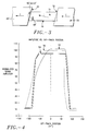
- FIG 2. is a front elevation view of the MR read transducer of FIG 1.
- FIG 3. is a top view of the MR read transducer of FIG 1.
- FIG 4. is a graphical representation of the off-track performance of the MR read transducer of FIG 1.
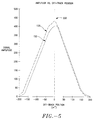
- FIG 5. is another graphical representation of the off-track performance of the MR read transducer of FIG 1.
- FIG 6. is a cross-sectional view of another embodiment of a MR read transducer according to the principles of the invention.
- FIG 7. is a front elevation view of the MR read transducer of FIG 6.
- the magnetoresistive (MR) sensor 10 comprises of a soft adjacent layer (SAL) 12, a non magnetic decoupling layer 14, a magnetoresistive (MR) layer 16, an antiferromagnetic (AFM) layer 18, conductive leads 20, 20' and magnetic shields 26, 26'.
- SAL soft adjacent layer
- MR magnetoresistive
- AFM antiferromagnetic
- the MR sensor 10 is provided with longitudinal and transverse bias.
- the longitudinal bias for domain suppression is applied only to the end regions 22 of the MR sensor 10.
- the longitudinal bias is produced by an exchange biasing method.
- the MR sensor 10 has a MR layer 16 which is in electrical contact with an antiferromagnetic (AFM) layer 18.
- the AFM layer 18 is patterned to cover the end regions 22 of the MR sensor 10. Therefore, only the end regions 22 of the MR sensor 10 are exchange biased so that the MR layer 16 is longitudinally biased in a single domain mode in the end regions 22.
- the MR layer 16 on the side opposite from the AFM layer 18, is in electrical contact with a nonmagnetic decoupling layer 14.
- the decoupling layer 14 is in electrical contact with a soft adjacent layer (SAL) 12.
- the SAL 12 is a soft magnetic film which provides a soft film transverse bias of the central region 24 of the MR layer 16.
- the nonmagnetic decoupling layer 14 provides the physical separation necessary for the MR layer 16 and the SAL 12 to produce opposite magnetization rotations.
- the SAL 12 and the nonmagnetic decoupling layer 14 combine to produce a transverse bias field in a central region of the MR layer 16.
- magnetic shields 26 and 26' are provided to minimize the effects of stray magnetic flux while providing higher signal amplitude at high linear recording densities.
- the conductive leads 20 and 20' are in electrical contact with the AFM layer 18.
- the conductive leads 20 and 20' have facing surfaces 32 and 30 respectively as shown in FIGs 1 and 2.
- the facing surfaces 32 and 30 of the conductive leads 20 and 20' are parallel to each other and define an active region 24 therebetween.
- the active region 24 is generally aligned with the central region of the MR layer 16, as shown in FIGS 1 and 2.
- the transverse bias field provided by the SAL 12 maintains the active region 24 in a linear response mode.
- the facing surfaces 32 and 34 of the conductive leads 20 and 20' are canted to define an angle ⁇ with respect to a plane extending through the true easy axis 38 of the MR layer 16.
- good results have been obtained by canting the leads 20 and 20' at an angle of 78°, that is, ⁇ is 78°.
- the leads 20 and 20' can be canted at an any angle ⁇ within the range of 80°-65° to obtain good results also, according to the principles of the invention.
- the height of the MR element 16 also called the stripe height 45 is 2.8 microns, as shown in FIG 2. Good results have also been obtained by using stripe heights of 2.5-3.0 microns.
- Magnetic flux in a conventional MR head enters the active region only when magnetic charge on the magnetic media is underneath the active region.
- the active region 24 picks up a magnetic charge even when the charge is still away from the active area, that is, even when the charge is not underneath the active region 24.
- canting the leads 20 and 20' at an angle of 78° results in a more symmetrical off-track performance profile as depicted by off-track performance curve 50.
- the MR stripe height 45 for the MR head 10 exhibiting off-track performance curve 50 is 2.8 microns.
- the off-track performance curve 54 of a MR head having stripe height 45 of 1.4 microns is the preferred strip height because reducing the stripe height to 1.4 microns significantly degrades the signal to noise ratio of the magnetic recording system.
- the asymmetric off-track performance of a conventional MR sensor is represented by curve 52 in FIG 4.
- FIG 5 shown in FIG 5 is another graphical representation of the off-track performance of the MR read transducer of FIG 1 according to the principles of the invention.
- canting the leads 20 and 20' at an angle of 78° results in a more symmetrical off-track performance profile as depicted by off-track performance curve 150.
- the asymmetric off-track performance of a conventional MR sensor is represented by curve 152 in FIG 4.
- a measure of the symmetry of a performance curve is obtained by computing the slope asymmetry for the curve.
- SlopeAssymetry Slope 1- Slope 2 0.5( Slope 1+ Slope 2) where, slope1 is the slope of a performance curve to the left of line 200 on Fig 5, while slope2 is the slope of a performance curve to the right of line 200 on Fig 5.
- the slope asymmetry calculated using the aforementioned equation, is 1.6% for off-track performance curve 150 for an MR head 10 with leads 20 and 20' canted at an angle of 78°.
- the slope asymmetry is 3.1% for off-track performance curve 152 for a conventional MR head having un-canted leads. Therefore, it is quite clear that canting the leads 20 and 20' at an angle of 78°, results in more symmetrical off-track performance.
- FIGs 6 and 7 another embodiment of a magnetoresistive device 110 in accordance with the present invention is shown.
- the embodiment of FIGs 6 and 7 is different in structure from that of FIGs 1 and 2 in that it uses a permanent magnet for longitudinal biasing as opposed to using an antiferromagnetic layer.
- magnetoresistive (MR) sensor 110 comprises of a soft adjacent layer (SAL) 112, a non magnetic decoupling layer 114, a magnetoresistive (MR) layer 116, permanent magnets 118, conductive leads 120, 120' and magnetic shields 126, 126'.
- SAL soft adjacent layer
- MR magnetoresistive
- the MR sensor 110 is provided with longitudinal and transverse bias.
- the longitudinal bias for domain suppression is applied only to the end regions 122 of the MR sensor 110.
- the longitudinal bias is produced by permanent magnets 118.
- the MR sensor 110 has a trilayer structure comprising MR layer 116, soft adjacent layer (SAL) 112, and non-magnetic decoupling layer 114.
- SAL soft adjacent layer
- permanent magnets 118 are located at opposite sides of the trilayer structure so that the MR layer 116 is longitudinally biased in a single domain mode in the end regions 122.
- the MR layer 116 is in electrical contact with a nonmagnetic decoupling layer 114.
- the decoupling layer 114 is in electrical contact with a soft adjacent layer (SAL) 112.
- magnetic shields 126 and 126' are provided to minimize the effects of stray magnetic flux while providing higher signal amplitude at high linear recording densities.
- the conductive leads 120 and 120' are in electrical contact with the MR layer 116 and permanent magnets 118.
- the conductive leads 120 and 120' have facing surfaces 132 and 130 respectively as shown in FIGs 6 and 7.
- the facing surfaces 132 and 130 of the conductive leads 120 and 120' are parallel to each other and define an active region 124 therebetween.
- the transverse bias field provided by the SAL 112 maintains the active region 124 in a linear response mode.
- the facing surfaces 132 and 134 of the conductive leads 120 and 120' are canted to define an angle ⁇ with respect to a plane extending through the true easy axis 138 of the MR layer 116.
- good results have been obtained by canting the leads 120 and 120' at an angle of 78°, that is, ⁇ is 78°.
- the leads 120 and 120' can be canted at an any angle ⁇ within the range of 80°-65° to obtain good results also.
- FIGs 6 and 7 having leads 120 and 120' canted at an angle of 78°, according to the principles of the invention, results in a more symmetrical off-track performance profile as depicted by off-track performance curve 50 of FIG 4.
Landscapes
- Engineering & Computer Science (AREA)
- Physics & Mathematics (AREA)
- Chemical & Material Sciences (AREA)
- Nanotechnology (AREA)
- Condensed Matter Physics & Semiconductors (AREA)
- General Physics & Mathematics (AREA)
- Crystallography & Structural Chemistry (AREA)
- Manufacturing & Machinery (AREA)
- Magnetic Heads (AREA)
Applications Claiming Priority (2)
| Application Number | Priority Date | Filing Date | Title |
|---|---|---|---|
| US08/259,795 US5483402A (en) | 1994-06-15 | 1994-06-15 | Magneto resistive head having symmetric off-track performance profile |
| US259795 | 1999-03-01 |
Publications (2)
| Publication Number | Publication Date |
|---|---|
| EP0687918A2 true EP0687918A2 (de) | 1995-12-20 |
| EP0687918A3 EP0687918A3 (de) | 1997-06-18 |
Family
ID=22986423
Family Applications (1)
| Application Number | Title | Priority Date | Filing Date |
|---|---|---|---|
| EP95303815A Withdrawn EP0687918A3 (de) | 1994-06-15 | 1995-06-05 | Magnetoresistiver Kopf mit verbesserte Aus-Spur-Leistung |
Country Status (4)
| Country | Link |
|---|---|
| US (1) | US5483402A (de) |
| EP (1) | EP0687918A3 (de) |
| JP (1) | JPH0855311A (de) |
| KR (1) | KR960002150A (de) |
Families Citing this family (19)
| Publication number | Priority date | Publication date | Assignee | Title |
|---|---|---|---|---|
| JPH07320247A (ja) * | 1994-05-23 | 1995-12-08 | Internatl Business Mach Corp <Ibm> | Mrヘッド用サーボ方法及びハードディスクシステム |
| JPH0845027A (ja) * | 1994-07-29 | 1996-02-16 | Fujitsu Ltd | 磁気抵抗効果素子及びその製造方法 |
| JPH0845030A (ja) * | 1994-08-03 | 1996-02-16 | Alps Electric Co Ltd | 磁気抵抗効果型磁気ヘッド |
| US5754376A (en) * | 1995-09-12 | 1998-05-19 | Hitachi Metals, Ltd. | Magnetoresistive head with hard magnetic bias |
| US5627704A (en) * | 1996-02-12 | 1997-05-06 | Read-Rite Corporation | Thin film giant magnetoresistive CPP transducer with flux guide yoke structure |
| JP3461999B2 (ja) * | 1996-03-28 | 2003-10-27 | 株式会社東芝 | 磁気抵抗効果素子 |
| EP0801380A3 (de) * | 1996-04-10 | 1998-03-04 | Read-Rite Corporation | Riesenmagnetoresistive Wandler mit erhöhtem Ausgangssignal |
| US6088181A (en) * | 1996-05-30 | 2000-07-11 | Kabushiki Kaisha Toshiba | Magnetic recording/reproducing device using composite head |
| US5739988A (en) * | 1996-09-18 | 1998-04-14 | International Business Machines Corporation | Spin valve sensor with enhanced magnetoresistance |
| US5739990A (en) * | 1996-11-13 | 1998-04-14 | Read-Rite Corporation | Spin-valve GMR sensor with inbound exchange stabilization |
| US5883762A (en) * | 1997-03-13 | 1999-03-16 | Calhoun; Robert B. | Electroplating apparatus and process for reducing oxidation of oxidizable plating anions and cations |
| US5850324A (en) * | 1997-03-13 | 1998-12-15 | Quantum Corporation | Magnetoresistive head having electrically isolated conductor leads |
| US5949623A (en) * | 1997-09-11 | 1999-09-07 | International Business Machines Corporation | Monolayer longitudinal bias and sensor trackwidth definition for overlaid anisotropic and giant magnetoresistive heads |
| US6103136A (en) | 1998-03-23 | 2000-08-15 | Headway Technologies, Inc. | Method for forming a soft adjacent layer (SAL) magnetoresistive (MR) sensor element with transversely magnetically biased soft adjacent layer (SAL) |
| US6583971B1 (en) * | 1999-03-09 | 2003-06-24 | Sae Magnetics (Hk) Ltd. | Elimination of electric-pop noise in MR/GMR device |
| US8343319B1 (en) | 2008-09-25 | 2013-01-01 | Western Digital (Fremont), Llc | Method and system for providing an improved hard bias structure |
| US8240024B2 (en) | 2009-08-25 | 2012-08-14 | International Business Machines Corporation | Methods for fabricating magnetic transducers using post-deposition tilting |
| US8351152B2 (en) | 2009-08-25 | 2013-01-08 | International Business Machines Corporation | Magnetic writer structures formed using post-deposition tilting |
| US8416537B2 (en) * | 2009-11-06 | 2013-04-09 | International Business Machines Corporation | Recording head with tilted orientation |
Citations (4)
| Publication number | Priority date | Publication date | Assignee | Title |
|---|---|---|---|---|
| US4663685A (en) | 1985-08-15 | 1987-05-05 | International Business Machines | Magnetoresistive read transducer having patterned longitudinal bias |
| US4967298A (en) | 1987-02-17 | 1990-10-30 | Mowry Greg S | Magnetic head with magnetoresistive sensor, inductive write head, and shield |
| US5005096A (en) | 1988-12-21 | 1991-04-02 | International Business Machines Corporation | Magnetoresistive read transducer having hard magnetic shunt bias |
| US5079035A (en) | 1989-10-10 | 1992-01-07 | International Business Machines Corporation | Method of making a magnetoresistive read transducer having hard magnetic bias |
Family Cites Families (13)
| Publication number | Priority date | Publication date | Assignee | Title |
|---|---|---|---|---|
| DE3413309A1 (de) * | 1984-04-09 | 1985-10-17 | Alexander 7128 Lauffen Mollerus | Vorrichtung zum entwaessern von nasswaesche |
| US4891725A (en) * | 1987-02-17 | 1990-01-02 | Magnetic Peripherals Inc. | Magnetoresistive sensor having antiferromagnetic exchange-biased ends |
| US4841398A (en) * | 1987-02-17 | 1989-06-20 | Magnetic Peripherals Inc. | Non linear magnetoresistive sensor |
| JPH02187912A (ja) * | 1989-01-13 | 1990-07-24 | Fujitsu Ltd | 磁気抵抗効果型再生ヘッド |
| US5018037A (en) * | 1989-10-10 | 1991-05-21 | Krounbi Mohamad T | Magnetoresistive read transducer having hard magnetic bias |
| US5155642A (en) * | 1989-11-29 | 1992-10-13 | International Business Machines Corporation | Anisotropy configuration for longitudinally constrained magnetoresistive transducers |
| JP2765175B2 (ja) * | 1990-03-27 | 1998-06-11 | 日本電気株式会社 | 磁気抵抗効果形ヘッド装置 |
| JPH04255276A (ja) * | 1991-02-07 | 1992-09-10 | Fujitsu Ltd | 磁気抵抗素子 |
| JPH0554338A (ja) * | 1991-08-29 | 1993-03-05 | Hitachi Ltd | 磁気抵抗効果型磁気ヘツド |
| EP0551603B1 (de) * | 1991-12-05 | 1998-12-02 | Matsushita Electric Industrial Co., Ltd. | Magnetoresistiver Kopf |
| JPH05258246A (ja) * | 1992-01-21 | 1993-10-08 | Internatl Business Mach Corp <Ibm> | 磁気抵抗読取りトランスジューサ |
| US5260652A (en) * | 1992-03-25 | 1993-11-09 | Seagate Technology, Inc. | Magnetoresistive sensor with electrical contacts having variable resistive regions for enhanced sensor sensitivity |
| DE69329669D1 (de) * | 1992-08-25 | 2000-12-21 | Seagate Technology Llc | Magnetoresistiver Sensor und Herstellungsverfahren dafür |
-
1994
- 1994-06-15 US US08/259,795 patent/US5483402A/en not_active Expired - Fee Related
-
1995
- 1995-06-05 EP EP95303815A patent/EP0687918A3/de not_active Withdrawn
- 1995-06-13 JP JP7145964A patent/JPH0855311A/ja active Pending
- 1995-06-14 KR KR1019950015664A patent/KR960002150A/ko not_active Withdrawn
Patent Citations (4)
| Publication number | Priority date | Publication date | Assignee | Title |
|---|---|---|---|---|
| US4663685A (en) | 1985-08-15 | 1987-05-05 | International Business Machines | Magnetoresistive read transducer having patterned longitudinal bias |
| US4967298A (en) | 1987-02-17 | 1990-10-30 | Mowry Greg S | Magnetic head with magnetoresistive sensor, inductive write head, and shield |
| US5005096A (en) | 1988-12-21 | 1991-04-02 | International Business Machines Corporation | Magnetoresistive read transducer having hard magnetic shunt bias |
| US5079035A (en) | 1989-10-10 | 1992-01-07 | International Business Machines Corporation | Method of making a magnetoresistive read transducer having hard magnetic bias |
Also Published As
| Publication number | Publication date |
|---|---|
| US5483402A (en) | 1996-01-09 |
| EP0687918A3 (de) | 1997-06-18 |
| KR960002150A (ko) | 1996-01-26 |
| JPH0855311A (ja) | 1996-02-27 |
Similar Documents
| Publication | Publication Date | Title |
|---|---|---|
| US5483402A (en) | Magneto resistive head having symmetric off-track performance profile | |
| US5073836A (en) | Single pole write and a differential magneto-resistive read for perpendicular recording | |
| KR100259429B1 (ko) | 강화된 자기저항을 갖는 스핀 밸브 센서 | |
| US5388014A (en) | Apparatus and method of sensing the position of a magnetic head | |
| JPH0439738B2 (de) | ||
| US5963401A (en) | Magnetic tape head assembly including modules having a plurality of magneto-resistive head elements | |
| US5883763A (en) | Read/write head having a GMR sensor biased by permanent magnets located between the GMR and the pole shields | |
| US5406433A (en) | Dual magnetoresistive head for reproducing very narrow track width short wavelength data | |
| WO1998029871A1 (en) | Hard disk drive having contact write and recessed magnetoresistive read head | |
| US6456460B1 (en) | Track width definition by patterning of shared pole for integrated thin film/magnetoresistive head | |
| US5754376A (en) | Magnetoresistive head with hard magnetic bias | |
| US20020181164A1 (en) | Single domain state laminated thin film structure for use as a magnetic layer of a transducing head | |
| US4547824A (en) | Dual biasing for integrated inductive MR head | |
| US4851944A (en) | Ganged MR head sensor | |
| US20070030594A1 (en) | Tape recording head with overlapping read transducers | |
| US5493466A (en) | Composite thin film recording/reproducing head with MR reproducing head having greater track width than recording head | |
| KR0162119B1 (ko) | 엣지가 바이어스된 자기 저항 센서 | |
| JP3377710B2 (ja) | 磁気抵抗装置および磁気センサ | |
| KR0145034B1 (ko) | 자기 트랜스듀서와, 자기 트랜스듀서를 포함하는 매체 드라이브 | |
| EP0702357B1 (de) | Magnetowiderstandeffektkopf und Magnetaufzeichnungs-/Wiedergabekopf daraus | |
| JPH05135332A (ja) | 磁気抵抗効果再生ヘツドおよびそれを用いた磁気記録装置 | |
| US6801410B2 (en) | Side flux guide for current perpendicular to plane magnetoresistive transducer | |
| JP3443971B2 (ja) | 磁気記録信号再生方法 | |
| JP3039482B2 (ja) | 磁気抵抗効果型ヘッドおよびこれを用いた磁気記録再生装置 | |
| JP3361345B2 (ja) | 磁気記録装置 |
Legal Events
| Date | Code | Title | Description |
|---|---|---|---|
| PUAI | Public reference made under article 153(3) epc to a published international application that has entered the european phase |
Free format text: ORIGINAL CODE: 0009012 |
|
| AK | Designated contracting states |
Kind code of ref document: A2 Designated state(s): DE FR GB IT NL |
|
| PUAL | Search report despatched |
Free format text: ORIGINAL CODE: 0009013 |
|
| AK | Designated contracting states |
Kind code of ref document: A3 Designated state(s): DE FR GB IT NL |
|
| 17P | Request for examination filed |
Effective date: 19970714 |
|
| RAP1 | Party data changed (applicant data changed or rights of an application transferred) |
Owner name: MATSUSHITA-KOTOBUKI ELECTRONICS INDUSTRIES, LTD. |
|
| STAA | Information on the status of an ep patent application or granted ep patent |
Free format text: STATUS: THE APPLICATION IS DEEMED TO BE WITHDRAWN |
|
| 18D | Application deemed to be withdrawn |
Effective date: 20010103 |