EP0716476A2 - Couvercle de connecteur électrique pour atténuer l'effort de tension - Google Patents
Couvercle de connecteur électrique pour atténuer l'effort de tension Download PDFInfo
- Publication number
- EP0716476A2 EP0716476A2 EP95870125A EP95870125A EP0716476A2 EP 0716476 A2 EP0716476 A2 EP 0716476A2 EP 95870125 A EP95870125 A EP 95870125A EP 95870125 A EP95870125 A EP 95870125A EP 0716476 A2 EP0716476 A2 EP 0716476A2
- Authority
- EP
- European Patent Office
- Prior art keywords
- latch
- strain relief
- side wall
- cable
- main body
- Prior art date
- Legal status (The legal status is an assumption and is not a legal conclusion. Google has not performed a legal analysis and makes no representation as to the accuracy of the status listed.)
- Withdrawn
Links
Images
Classifications
-
- H—ELECTRICITY
- H01—ELECTRIC ELEMENTS
- H01R—ELECTRICALLY-CONDUCTIVE CONNECTIONS; STRUCTURAL ASSOCIATIONS OF A PLURALITY OF MUTUALLY-INSULATED ELECTRICAL CONNECTING ELEMENTS; COUPLING DEVICES; CURRENT COLLECTORS
- H01R13/00—Details of coupling devices of the kinds covered by groups H01R12/70 or H01R24/00 - H01R33/00
- H01R13/46—Bases; Cases
- H01R13/516—Means for holding or embracing insulating body, e.g. casing, hoods
-
- H—ELECTRICITY
- H01—ELECTRIC ELEMENTS
- H01R—ELECTRICALLY-CONDUCTIVE CONNECTIONS; STRUCTURAL ASSOCIATIONS OF A PLURALITY OF MUTUALLY-INSULATED ELECTRICAL CONNECTING ELEMENTS; COUPLING DEVICES; CURRENT COLLECTORS
- H01R13/00—Details of coupling devices of the kinds covered by groups H01R12/70 or H01R24/00 - H01R33/00
- H01R13/58—Means for relieving strain on wire connection, e.g. cord grip, for avoiding loosening of connections between wires and terminals within a coupling device terminating a cable
- H01R13/5804—Means for relieving strain on wire connection, e.g. cord grip, for avoiding loosening of connections between wires and terminals within a coupling device terminating a cable comprising a separate cable clamping part
- H01R13/5812—Means for relieving strain on wire connection, e.g. cord grip, for avoiding loosening of connections between wires and terminals within a coupling device terminating a cable comprising a separate cable clamping part the cable clamping being achieved by mounting the separate part on the housing of the coupling device
-
- H—ELECTRICITY
- H01—ELECTRIC ELEMENTS
- H01R—ELECTRICALLY-CONDUCTIVE CONNECTIONS; STRUCTURAL ASSOCIATIONS OF A PLURALITY OF MUTUALLY-INSULATED ELECTRICAL CONNECTING ELEMENTS; COUPLING DEVICES; CURRENT COLLECTORS
- H01R13/00—Details of coupling devices of the kinds covered by groups H01R12/70 or H01R24/00 - H01R33/00
- H01R13/62—Means for facilitating engagement or disengagement of coupling parts or for holding them in engagement
- H01R13/627—Snap or like fastening
- H01R13/6275—Latching arms not integral with the housing
Definitions
- the present invention relates to electrical connectors and, more particularly, to a strain relief hood for an electrical connector.
- MILLIPACS 1 has a strain relief hood that is snap-lock mounted on a housing of a first connector and a connector latch for a second connector that is slidingly mounted to the strain relief hood.
- an electrical cable assembly comprising a plurality of electrical wires, an electrical connector body, and a strain relief hood.
- the connector body is connected to first ends of the electrical wires.
- the strain relief hood is connected to the connector body and the wires.
- the hood has a first section snap-lock connected to the connector body and a second section attached to the cable.
- the first section includes a cantilevered side wall formed, at least partially, by two slots between the side wall and two adjacent side walls.
- a strain relief for an electrical cable and an electrical connector comprising a main body, a latch, and a fastener.
- the main body has a first end with a snap-lock section adapted to snap-lock connect to the electrical connector, a second end with a cable support surface, and a cable channel between the first and second ends.
- the latch is adapted to mount to the main body over the snap-lock section. The latch substantially prevents the snap-lock section from being outwardly reflected.
- the fastener is adapted to mount to the second end of the main body for holding the cable against the cable support surface.
- a method of assembling an electrical cable assembly comprising steps of connecting an electrical connector to wires of an electrical cable; snap-lock mounting a snap-lock section of a strain relief main body to the connector; and attaching a latch to the main body over the snap-lock section to prevent the snap-lock section from being substantially moved relative to the rest of the main body while the latch is attached to the main body.
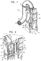
- FIG. 1 there is shown a perspective view of an end of an electrical cable assembly 10 incorporating features of the present invention.
- the present invention will be described with reference to the single embodiment shown in the drawings, it should be understood that the present invention could be embodied in many different types of alternative embodiments. In addition, any suitable size, shape or type of elements or materials could be used.
- the cable assembly 10 generally comprises an electrical cable 12 having electrical wires 13, and a connector assembly 14.
- the connector assembly 14 includes a connector body 16, electrical contacts (not shown), a strain relief hood 18, a second connector latch 20, and a cable fastener 22.
- the connector body 16 is preferably made of a dielectric plastic or polymer material and has a front end 24 adapted for connection to a second mating electrical connector (not shown).
- the electrical contacts (not shown) of the connector assembly 14 are fixedly mounted in the connector body 16. First ends of the wires 13 are connected to the contacts.
- the wires 13 extend out of the rear end 26 of the connector body 16 into the hood 18.
- projections 28 Located on two opposite sides of the connector body 16 are projections 28 for connecting the connector body 16 to the hood 18.
- the projections 28 have a wedge-like shape with a latching surface 30 facing the front of the connector body 16.
- the hood 18 and latch 20 are preferably comprised of a dielectric resilient plastic or polymer material.
- the hood 18 forms a main body for the strain relief of the wires 13.
- the hood 18 has a first end 32 with a snap-lock section, a second end 34 with a cable support surface 36, and a channel 38 between the two ends 32, 34.
- the snap-lock section includes two opposite sides 40, 41 of the hood 18 that extend past the adjacent sides 42, 43. Both extended sides 40, 41 have holes 44 adapted to receive the projections 28 of the connector body 16.
- a receiving area 46 is formed between the two extended sides 40, 41 for receiving the rear portion of the connector body 16.
- the first extended side 40 also includes two slots 48 that extend into the channel 38.
- the slots 48 are located proximate the side walls 42, 43 and extend about two-thirds the length of the walls 42, 43.
- the wall 40 has a general cantilever configuration.
- the walls 42, 43 have inwardly facing rails 50 located past a portion of the cantilevered wall 40.
- the cantilevered wall 40 also has an exterior projecting lug 52 and a locking projection 54.
- the second end 34 has a hole 56 for passing the fastener 22 through.
- the fastener 22, in this embodiment, is merely a strap to hold the cable 12 against the surface 36.
- the latch 20 has a base section 58, and two lever sections 60 and 62.
- the lever sections 60, 62 are formed integral with the base section 58 on pedestal pivot sections 64, 66.
- the base section 58 has two tracks 68 on opposite sides adapted to slidingly ride between the two rails 50 of the hood 18.
- the back end of the base section 58 also has a recess (not shown) for mating with the projecting lug 52 and locking with the locking projection 54.
- the first lever section 60 has latching projections 70 for making a latching engagement with a mating electrical connector (not shown).
- the second lever section 62 has a first end 72 located under an end 74 of the first lever section 60, and a second end 76 adapted to be depressed by a user's finger. When the second end 76 is depressed by a user, the latching projections 70 are retracted towards the connector body 16 to unlatch the two connectors from each other.
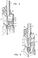
- the electrical contacts (not shown) are first connected to the individual wires 13. of the cable 12 and inserted into the connector body 16. Then the hood 18 is snap-lock connected to the connector body 16 with the cable 12 passing through channel 38. During the snap-lock connecting procedure, the cantilevered side wall 40 is outwardly deflected until the holes 44 on the two sides 40, 41 come into registry with the projections 28 on the connector body 16. When this happens, the cantilevered side wall 40 snaps back to its original position with the projections 28 being located in the holes 44. This effectively locks the connector body 16 to the hood 18. Referring also to Fig. 4, the latch 20 is then mounted on the hood 18.
- the latch 20 is slid on and between the rails 50 of the hood 18 and makes a mating and interlocking engagement with the lug 52 and locking projection 54. A portion of the base section 58 is interlocked behind the lug 52 in areas 53. With the latch 20 securely in place, the base section 58 substantially prevents the outward deflection of the cantilevered wall 40, at least at the area between the two adjacent walls 42, 43. This effectively eliminates the cantilever function of the slots 48.
- the cantilevered wall 40 allows the hood 18 to be relatively easily outwardly deflected for connection to the connector body 16, after the latch 20 is attached to the hood 18 the wall 40 is very hard to outwardly deflect.
- the relatively long cantilever length of the cantilevered wall 40 helps to assure that the wall 40 will not be permanently deformed during snap-locking to the connector body 16.
- the latch 20 can be removed from the hood 18 and the hood 18 then removed from the connector body 16 to repair the connection of the wires 13 to the contacts or the contacts themselves. After the latch 20 is mounted to the hood 18, the cable 12 is then positioned against the cable support surface 36 and the fastener 22 is attached.
- connector bodies, hoods, latches and/or fasteners could be adapted to incorporate the present invention.
- Other types of interlocks between the connector body and the hood, and/or the hood and the latch could be provided.
- the assembly could include any suitable type of member to be positioned on the cantilevered wall and its adjacent walls.
- the cable support surface could also have any suitable direction or shape.
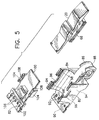
- the main body of the strain relief hood is comprised of a first member 80 and a second member 82.
- the latch 20 is the same latch seen in Figs. 1, 2 and 4.
- the first member 80 has a channel 84 with a substantially open side area.
- the channel 84 is to locate a cable in.
- the first member 80 has an end 86 with a cable support surface 88 and an opposite end 90 with holes 92 adapted to receive projections 28 of the connector body 16 (see Fig. 3).
- the lateral sides 94 of the first member 80, adjacent the substantially open side, each have a notch 96 and latch mounting rails 98.
- the mounting rails face each other across the substantially open side.
- the second member 82 has a center section 100, an end 102, and two lateral projections 104.
- the center section 100 is suitably sized and shaped to be located in the substantially open side of the first member 80 to substantially close that side.
- the end 102 has holes 106 adapted to receive projections 28 of the connector body 16 (see Fig. 3).
- the two lateral projections 104 are suitably sized and shaped to fit in the two notches 96 of the first member 80.
- the projections 104 each extend above the center section 100 and have rails 108 that are aligned with the rails 98 when the second member 82 is mounted on the first member 80.
- the latch 20 prevents the second member 82 from moving; both by having the rails 108 in the tracks 68 and, being located over the center section 100.
- other types of means to interlock and fix the two main body members to each other could be provided. This type of embodiment has the advantage of adding flexibility to the assembly process.
- cable and connector assemblies can be repaired by easily removing the strain relief hood. Connection of the connector latch to the hood main body could also take other forms and, the latch need not directly connect to the second member at the lateral projections.
Landscapes
- Details Of Connecting Devices For Male And Female Coupling (AREA)
Applications Claiming Priority (2)
| Application Number | Priority Date | Filing Date | Title |
|---|---|---|---|
| US08/350,620 US5620333A (en) | 1994-12-07 | 1994-12-07 | Electrical connector strain relief hood |
| US350620 | 1994-12-07 |
Publications (2)
| Publication Number | Publication Date |
|---|---|
| EP0716476A2 true EP0716476A2 (fr) | 1996-06-12 |
| EP0716476A3 EP0716476A3 (fr) | 1997-07-09 |
Family
ID=23377508
Family Applications (1)
| Application Number | Title | Priority Date | Filing Date |
|---|---|---|---|
| EP95870125A Withdrawn EP0716476A3 (fr) | 1994-12-07 | 1995-12-06 | Couvercle de connecteur électrique pour atténuer l'effort de tension |
Country Status (2)
| Country | Link |
|---|---|
| US (1) | US5620333A (fr) |
| EP (1) | EP0716476A3 (fr) |
Cited By (2)
| Publication number | Priority date | Publication date | Assignee | Title |
|---|---|---|---|---|
| EP1257009A3 (fr) * | 2001-05-08 | 2005-08-17 | REMA Lipprandt GmbH & Co. KG | Soulagement de traction pour connecteur enfichable à contact plat unique et connecteur enfichable avec celui-ci |
| WO2008068164A3 (fr) * | 2006-12-07 | 2008-08-07 | Osram Gmbh | Dispositif de verrouillage pour un connecteur enfichable |
Families Citing this family (12)
| Publication number | Priority date | Publication date | Assignee | Title |
|---|---|---|---|---|
| DE19636007A1 (de) * | 1996-09-05 | 1998-03-12 | Giovanni Miranda | Deckelklammer für einen Kabelkanal |
| US5910026A (en) * | 1997-02-04 | 1999-06-08 | Molex Incorporated | Electrical connector with cable strain relief |
| US6050840A (en) * | 1997-08-08 | 2000-04-18 | Coleman Cable Systems, Inc. | Electrical plug |
| US6231392B1 (en) | 1997-10-01 | 2001-05-15 | Berg Technology, Inc. | Cable interconnection |
| US6083038A (en) * | 1998-08-05 | 2000-07-04 | Osram Sylvania Inc. | Bracket assembly |
| KR100567293B1 (en) * | 1998-09-30 | 2006-05-25 | Cable interconnection | |
| EP1403967B1 (fr) * | 2002-09-30 | 2010-12-15 | Fujikura Ltd. | Stucture de connexion d'un dispositif accessoire, structure d'étanchéité de câble d'un dispositif accessoire et structure de montage d'un dispositif accessoire |
| WO2007050438A1 (fr) * | 2005-10-24 | 2007-05-03 | 3M Innovative Properties Company | Connecteur pour circuits à basse tension |
| US8037895B2 (en) | 2008-05-20 | 2011-10-18 | Vivant Medical, Inc. | Coolant line clip assemblies for use with fluid delivery systems |
| KR101701665B1 (ko) * | 2013-03-29 | 2017-02-01 | 미쓰비시덴키 가부시키가이샤 | 시퀀서 단자대, 시퀀서 및 시퀀서 유닛 |
| JP5951671B2 (ja) * | 2014-03-31 | 2016-07-13 | 本田技研工業株式会社 | 車両 |
| DE102018010384B4 (de) | 2018-01-30 | 2024-06-27 | Wago Verwaltungsgesellschaft Mbh | Elektrische Steckverbindung |
Family Cites Families (17)
| Publication number | Priority date | Publication date | Assignee | Title |
|---|---|---|---|---|
| US3701071A (en) * | 1971-01-18 | 1972-10-24 | Berg Electronics Inc | Hinge type circuit board connector block |
| FR2235571A1 (en) * | 1973-06-28 | 1975-01-24 | Gen Cable Corp | Printed circuit board connection - consists of grip with slot on board for plug-in tongue fitted connector |
| JPS5749913Y2 (fr) * | 1979-09-05 | 1982-11-01 | ||
| US4341431A (en) * | 1980-06-16 | 1982-07-27 | Amp Incorporated | Strain relief |
| US4449776A (en) * | 1982-09-13 | 1984-05-22 | Pacific Electricord Company | Electrical connector having opposed locking ramp members |
| US4607903A (en) * | 1984-03-30 | 1986-08-26 | Japan Aviation Electronics Industry Limited | Connector assembly |
| GB8611897D0 (en) * | 1986-05-15 | 1986-06-25 | Kinloch Electronics Ltd | Modified connector hood |
| US4714433A (en) * | 1987-01-21 | 1987-12-22 | General Motors Corporation | Electrical connector with position assurance and double lock |
| US4812003A (en) * | 1987-11-10 | 1989-03-14 | Molex Incorporated | Optic sensing assembly |
| US4787860A (en) * | 1987-08-28 | 1988-11-29 | E. I. Du Pont De Nemours And Company | Connector system having combined latch and polarization member |
| JPH0638378Y2 (ja) * | 1987-09-30 | 1994-10-05 | 矢崎総業株式会社 | コネクタ |
| JPH01137572A (ja) * | 1987-11-25 | 1989-05-30 | Yazaki Corp | コネクタのロック機構 |
| JPH0433666Y2 (fr) * | 1988-05-13 | 1992-08-12 | ||
| JPH082939Y2 (ja) * | 1988-05-30 | 1996-01-29 | 矢崎総業株式会社 | コネクタの二重ロック装置 |
| US4842550A (en) * | 1988-07-01 | 1989-06-27 | Molex Incorporated | Integrally molded environmentally protected strain relief backshell |
| JPH079343Y2 (ja) * | 1990-04-10 | 1995-03-06 | 矢崎総業株式会社 | 端子係止具付コネクタ |
| US5403199A (en) * | 1993-10-21 | 1995-04-04 | Electrical Mechanical Products Inc. | Low insertion force high current terminal |
-
1994
- 1994-12-07 US US08/350,620 patent/US5620333A/en not_active Expired - Fee Related
-
1995
- 1995-12-06 EP EP95870125A patent/EP0716476A3/fr not_active Withdrawn
Cited By (2)
| Publication number | Priority date | Publication date | Assignee | Title |
|---|---|---|---|---|
| EP1257009A3 (fr) * | 2001-05-08 | 2005-08-17 | REMA Lipprandt GmbH & Co. KG | Soulagement de traction pour connecteur enfichable à contact plat unique et connecteur enfichable avec celui-ci |
| WO2008068164A3 (fr) * | 2006-12-07 | 2008-08-07 | Osram Gmbh | Dispositif de verrouillage pour un connecteur enfichable |
Also Published As
| Publication number | Publication date |
|---|---|
| EP0716476A3 (fr) | 1997-07-09 |
| US5620333A (en) | 1997-04-15 |
Similar Documents
| Publication | Publication Date | Title |
|---|---|---|
| US5620333A (en) | Electrical connector strain relief hood | |
| EP1369964B1 (fr) | Dispositif pour assurer la position du connecteur | |
| EP0804821B1 (fr) | Element d'encliquetage de boitier avec dispositif de verification de la position de connecteurs | |
| JP3301329B2 (ja) | コネクタ | |
| EP0818855B1 (fr) | Connecteur | |
| US5605472A (en) | Connector fitting detection mechanism | |
| JP3092066B2 (ja) | コネクタ位置決め保証装置を備える電気コネクタ | |
| CA2519472C (fr) | Connecteur electrique comprenant un organe qui garantit la position du connecteur | |
| JP2887579B2 (ja) | ロック式電気コネクタとその製造方法 | |
| EP1235311B1 (fr) | Ensemble de connecteurs électriques avec organe d'accrochage latéralement flexible et élément de verrouillage et de vérification de la position des connecteurs | |
| US5944547A (en) | Connector shorting bar retention | |
| US5273453A (en) | Electrical connector with positive latch | |
| EP1009063A2 (fr) | Un connecteur | |
| US7534134B2 (en) | Electrical connector retaining mechanism having slide clip member | |
| US5496184A (en) | Header assembly for printed circuit board | |
| WO1998027624A1 (fr) | Verrou a ressort monobloc pour ensemble connecteur electrique | |
| JPH03116672A (ja) | 電気コネクタ | |
| JPH087982A (ja) | ラッチ付き電気コネクタ | |
| EP0305101A2 (fr) | Système connecteur avec organe combinant verrouillage et polarisation | |
| GB2330248A (en) | Mounting a connector in a panel | |
| EP1045486B1 (fr) | Assemblage d'un connecteur monté sur panneau | |
| EP0820647B1 (fr) | Connecteur electrique modulaire | |
| US5352133A (en) | Connector assembly having anti-overstress latch means | |
| US6835087B2 (en) | Locking mechanism for electrical connector | |
| US6152783A (en) | Double locking member for a connector |
Legal Events
| Date | Code | Title | Description |
|---|---|---|---|
| PUAI | Public reference made under article 153(3) epc to a published international application that has entered the european phase |
Free format text: ORIGINAL CODE: 0009012 |
|
| AK | Designated contracting states |
Kind code of ref document: A2 Designated state(s): BE DE FR NL SE |
|
| PUAL | Search report despatched |
Free format text: ORIGINAL CODE: 0009013 |
|
| AK | Designated contracting states |
Kind code of ref document: A3 Designated state(s): BE DE FR NL SE |
|
| 17P | Request for examination filed |
Effective date: 19971220 |
|
| STAA | Information on the status of an ep patent application or granted ep patent |
Free format text: STATUS: THE APPLICATION IS DEEMED TO BE WITHDRAWN |
|
| 18D | Application deemed to be withdrawn |
Effective date: 20010702 |