EP0717457B1 - Feuille poreuse métallique pour un substrat d'électrode de batterie, et méthode de production - Google Patents
Feuille poreuse métallique pour un substrat d'électrode de batterie, et méthode de production Download PDFInfo
- Publication number
- EP0717457B1 EP0717457B1 EP95118659A EP95118659A EP0717457B1 EP 0717457 B1 EP0717457 B1 EP 0717457B1 EP 95118659 A EP95118659 A EP 95118659A EP 95118659 A EP95118659 A EP 95118659A EP 0717457 B1 EP0717457 B1 EP 0717457B1
- Authority
- EP
- European Patent Office
- Prior art keywords
- sheet
- metallic
- porous
- fibers
- battery
- Prior art date
- Legal status (The legal status is an assumption and is not a legal conclusion. Google has not performed a legal analysis and makes no representation as to the accuracy of the status listed.)
- Expired - Lifetime
Links
- 239000000758 substrate Substances 0.000 title claims description 49
- 238000004519 manufacturing process Methods 0.000 title description 22
- 229920000914 Metallic fiber Polymers 0.000 claims description 128
- 239000000835 fiber Substances 0.000 claims description 97
- 239000011148 porous material Substances 0.000 claims description 80
- 239000013543 active substance Substances 0.000 claims description 72
- 239000000843 powder Substances 0.000 claims description 52
- PXHVJJICTQNCMI-UHFFFAOYSA-N Nickel Chemical compound [Ni] PXHVJJICTQNCMI-UHFFFAOYSA-N 0.000 claims description 39
- 229910052759 nickel Inorganic materials 0.000 claims description 16
- WHXSMMKQMYFTQS-UHFFFAOYSA-N Lithium Chemical compound [Li] WHXSMMKQMYFTQS-UHFFFAOYSA-N 0.000 claims description 12
- 239000011888 foil Substances 0.000 claims description 12
- 229910052744 lithium Inorganic materials 0.000 claims description 12
- 239000000126 substance Substances 0.000 claims description 12
- UFHFLCQGNIYNRP-UHFFFAOYSA-N Hydrogen Chemical compound [H][H] UFHFLCQGNIYNRP-UHFFFAOYSA-N 0.000 claims description 9
- 239000001257 hydrogen Substances 0.000 claims description 9
- 229910052739 hydrogen Inorganic materials 0.000 claims description 9
- OJIJEKBXJYRIBZ-UHFFFAOYSA-N cadmium nickel Chemical compound [Ni].[Cd] OJIJEKBXJYRIBZ-UHFFFAOYSA-N 0.000 claims description 8
- QNRATNLHPGXHMA-XZHTYLCXSA-N (r)-(6-ethoxyquinolin-4-yl)-[(2s,4s,5r)-5-ethyl-1-azabicyclo[2.2.2]octan-2-yl]methanol;hydrochloride Chemical compound Cl.C([C@H]([C@H](C1)CC)C2)CN1[C@@H]2[C@H](O)C1=CC=NC2=CC=C(OCC)C=C21 QNRATNLHPGXHMA-XZHTYLCXSA-N 0.000 claims description 2
- 229920005989 resin Polymers 0.000 description 79
- 239000011347 resin Substances 0.000 description 79
- 239000000203 mixture Substances 0.000 description 46
- 239000011230 binding agent Substances 0.000 description 43
- 229910052751 metal Inorganic materials 0.000 description 43
- 239000002184 metal Substances 0.000 description 43
- 238000000034 method Methods 0.000 description 39
- 238000007747 plating Methods 0.000 description 27
- 238000009987 spinning Methods 0.000 description 23
- 238000005245 sintering Methods 0.000 description 14
- 150000001875 compounds Chemical class 0.000 description 12
- 239000007787 solid Substances 0.000 description 10
- 150000002739 metals Chemical class 0.000 description 9
- XLYOFNOQVPJJNP-UHFFFAOYSA-N water Substances O XLYOFNOQVPJJNP-UHFFFAOYSA-N 0.000 description 9
- 238000001816 cooling Methods 0.000 description 8
- 239000008188 pellet Substances 0.000 description 7
- XEEYBQQBJWHFJM-UHFFFAOYSA-N Iron Chemical compound [Fe] XEEYBQQBJWHFJM-UHFFFAOYSA-N 0.000 description 6
- 239000000463 material Substances 0.000 description 6
- 229910045601 alloy Inorganic materials 0.000 description 5
- 239000000956 alloy Substances 0.000 description 5
- 238000007796 conventional method Methods 0.000 description 5
- 239000000853 adhesive Substances 0.000 description 4
- 238000007599 discharging Methods 0.000 description 4
- 238000002474 experimental method Methods 0.000 description 4
- 238000004898 kneading Methods 0.000 description 4
- 229920001778 nylon Polymers 0.000 description 4
- 230000002093 peripheral effect Effects 0.000 description 4
- -1 polypropylene Polymers 0.000 description 4
- 239000004677 Nylon Substances 0.000 description 3
- 229910052782 aluminium Inorganic materials 0.000 description 3
- 230000003247 decreasing effect Effects 0.000 description 3
- 230000002349 favourable effect Effects 0.000 description 3
- 239000012530 fluid Substances 0.000 description 3
- 229910052742 iron Inorganic materials 0.000 description 3
- 229920000728 polyester Polymers 0.000 description 3
- 239000000243 solution Substances 0.000 description 3
- RYGMFSIKBFXOCR-UHFFFAOYSA-N Copper Chemical compound [Cu] RYGMFSIKBFXOCR-UHFFFAOYSA-N 0.000 description 2
- 239000004698 Polyethylene Substances 0.000 description 2
- XAGFODPZIPBFFR-UHFFFAOYSA-N aluminium Chemical compound [Al] XAGFODPZIPBFFR-UHFFFAOYSA-N 0.000 description 2
- 238000005452 bending Methods 0.000 description 2
- 238000005253 cladding Methods 0.000 description 2
- 239000011889 copper foil Substances 0.000 description 2
- 238000009792 diffusion process Methods 0.000 description 2
- 238000010438 heat treatment Methods 0.000 description 2
- 239000007788 liquid Substances 0.000 description 2
- 238000002844 melting Methods 0.000 description 2
- 230000008018 melting Effects 0.000 description 2
- BFDHFSHZJLFAMC-UHFFFAOYSA-L nickel(ii) hydroxide Chemical compound [OH-].[OH-].[Ni+2] BFDHFSHZJLFAMC-UHFFFAOYSA-L 0.000 description 2
- 229920000573 polyethylene Polymers 0.000 description 2
- 229920000642 polymer Polymers 0.000 description 2
- 238000012545 processing Methods 0.000 description 2
- 239000010935 stainless steel Substances 0.000 description 2
- 229910001220 stainless steel Inorganic materials 0.000 description 2
- 239000002699 waste material Substances 0.000 description 2
- 229920002134 Carboxymethyl cellulose Polymers 0.000 description 1
- 229920002292 Nylon 6 Polymers 0.000 description 1
- 239000004642 Polyimide Substances 0.000 description 1
- 239000004743 Polypropylene Substances 0.000 description 1
- 239000012670 alkaline solution Substances 0.000 description 1
- 239000012298 atmosphere Substances 0.000 description 1
- 238000007664 blowing Methods 0.000 description 1
- CXKCTMHTOKXKQT-UHFFFAOYSA-N cadmium oxide Inorganic materials [Cd]=O CXKCTMHTOKXKQT-UHFFFAOYSA-N 0.000 description 1
- CFEAAQFZALKQPA-UHFFFAOYSA-N cadmium(2+);oxygen(2-) Chemical compound [O-2].[Cd+2] CFEAAQFZALKQPA-UHFFFAOYSA-N 0.000 description 1
- 238000009960 carding Methods 0.000 description 1
- 229920002678 cellulose Polymers 0.000 description 1
- 239000001913 cellulose Substances 0.000 description 1
- 229910052804 chromium Inorganic materials 0.000 description 1
- 239000011248 coating agent Substances 0.000 description 1
- 238000000576 coating method Methods 0.000 description 1
- GUTLYIVDDKVIGB-UHFFFAOYSA-N cobalt atom Chemical compound [Co] GUTLYIVDDKVIGB-UHFFFAOYSA-N 0.000 description 1
- 229910000428 cobalt oxide Inorganic materials 0.000 description 1
- IVMYJDGYRUAWML-UHFFFAOYSA-N cobalt(ii) oxide Chemical compound [Co]=O IVMYJDGYRUAWML-UHFFFAOYSA-N 0.000 description 1
- 238000010276 construction Methods 0.000 description 1
- 230000008602 contraction Effects 0.000 description 1
- 239000000498 cooling water Substances 0.000 description 1
- 229910052802 copper Inorganic materials 0.000 description 1
- 239000010949 copper Substances 0.000 description 1
- 238000005520 cutting process Methods 0.000 description 1
- 230000008021 deposition Effects 0.000 description 1
- 238000001035 drying Methods 0.000 description 1
- 230000000694 effects Effects 0.000 description 1
- 230000005611 electricity Effects 0.000 description 1
- 239000004744 fabric Substances 0.000 description 1
- 230000004927 fusion Effects 0.000 description 1
- 239000007789 gas Substances 0.000 description 1
- 229910052738 indium Inorganic materials 0.000 description 1
- 230000001788 irregular Effects 0.000 description 1
- 238000010030 laminating Methods 0.000 description 1
- 229910044991 metal oxide Inorganic materials 0.000 description 1
- 150000004706 metal oxides Chemical class 0.000 description 1
- 229920000609 methyl cellulose Polymers 0.000 description 1
- 239000001923 methylcellulose Substances 0.000 description 1
- 235000010981 methylcellulose Nutrition 0.000 description 1
- 238000002156 mixing Methods 0.000 description 1
- 238000012986 modification Methods 0.000 description 1
- 230000004048 modification Effects 0.000 description 1
- 239000003960 organic solvent Substances 0.000 description 1
- 239000002245 particle Substances 0.000 description 1
- 229920002239 polyacrylonitrile Polymers 0.000 description 1
- 229920001721 polyimide Polymers 0.000 description 1
- 229920001155 polypropylene Polymers 0.000 description 1
- 229920001343 polytetrafluoroethylene Polymers 0.000 description 1
- 239000004810 polytetrafluoroethylene Substances 0.000 description 1
- 229920002635 polyurethane Polymers 0.000 description 1
- 239000004814 polyurethane Substances 0.000 description 1
- 238000003825 pressing Methods 0.000 description 1
- 229910052709 silver Inorganic materials 0.000 description 1
- 238000003860 storage Methods 0.000 description 1
- 229910052718 tin Inorganic materials 0.000 description 1
- 229910052720 vanadium Inorganic materials 0.000 description 1
- 229920002554 vinyl polymer Polymers 0.000 description 1
- 229910052725 zinc Inorganic materials 0.000 description 1
Images







Classifications
-
- H—ELECTRICITY
- H01—ELECTRIC ELEMENTS
- H01M—PROCESSES OR MEANS, e.g. BATTERIES, FOR THE DIRECT CONVERSION OF CHEMICAL ENERGY INTO ELECTRICAL ENERGY
- H01M4/00—Electrodes
- H01M4/02—Electrodes composed of, or comprising, active material
-
- H—ELECTRICITY
- H01—ELECTRIC ELEMENTS
- H01M—PROCESSES OR MEANS, e.g. BATTERIES, FOR THE DIRECT CONVERSION OF CHEMICAL ENERGY INTO ELECTRICAL ENERGY
- H01M4/00—Electrodes
- H01M4/02—Electrodes composed of, or comprising, active material
- H01M4/64—Carriers or collectors
- H01M4/70—Carriers or collectors characterised by shape or form
- H01M4/72—Grids
- H01M4/74—Meshes or woven material; Expanded metal
- H01M4/745—Expanded metal
-
- B—PERFORMING OPERATIONS; TRANSPORTING
- B01—PHYSICAL OR CHEMICAL PROCESSES OR APPARATUS IN GENERAL
- B01D—SEPARATION
- B01D39/00—Filtering material for liquid or gaseous fluids
- B01D39/14—Other self-supporting filtering material ; Other filtering material
- B01D39/20—Other self-supporting filtering material ; Other filtering material of inorganic material, e.g. asbestos paper, metallic filtering material of non-woven wires
- B01D39/2027—Metallic material
- B01D39/2041—Metallic material the material being filamentary or fibrous
- B01D39/2044—Metallic material the material being filamentary or fibrous sintered or bonded by inorganic agents
-
- B—PERFORMING OPERATIONS; TRANSPORTING
- B22—CASTING; POWDER METALLURGY
- B22F—WORKING METALLIC POWDER; MANUFACTURE OF ARTICLES FROM METALLIC POWDER; MAKING METALLIC POWDER; APPARATUS OR DEVICES SPECIALLY ADAPTED FOR METALLIC POWDER
- B22F1/00—Metallic powder; Treatment of metallic powder, e.g. to facilitate working or to improve properties
- B22F1/06—Metallic powder characterised by the shape of the particles
- B22F1/062—Fibrous particles
-
- B—PERFORMING OPERATIONS; TRANSPORTING
- B22—CASTING; POWDER METALLURGY
- B22F—WORKING METALLIC POWDER; MANUFACTURE OF ARTICLES FROM METALLIC POWDER; MAKING METALLIC POWDER; APPARATUS OR DEVICES SPECIALLY ADAPTED FOR METALLIC POWDER
- B22F1/00—Metallic powder; Treatment of metallic powder, e.g. to facilitate working or to improve properties
- B22F1/14—Treatment of metallic powder
- B22F1/148—Agglomerating
-
- B—PERFORMING OPERATIONS; TRANSPORTING
- B22—CASTING; POWDER METALLURGY
- B22F—WORKING METALLIC POWDER; MANUFACTURE OF ARTICLES FROM METALLIC POWDER; MAKING METALLIC POWDER; APPARATUS OR DEVICES SPECIALLY ADAPTED FOR METALLIC POWDER
- B22F3/00—Manufacture of workpieces or articles from metallic powder characterised by the manner of compacting or sintering; Apparatus specially adapted therefor ; Presses and furnaces
- B22F3/002—Manufacture of articles essentially made from metallic fibres
-
- B—PERFORMING OPERATIONS; TRANSPORTING
- B22—CASTING; POWDER METALLURGY
- B22F—WORKING METALLIC POWDER; MANUFACTURE OF ARTICLES FROM METALLIC POWDER; MAKING METALLIC POWDER; APPARATUS OR DEVICES SPECIALLY ADAPTED FOR METALLIC POWDER
- B22F3/00—Manufacture of workpieces or articles from metallic powder characterised by the manner of compacting or sintering; Apparatus specially adapted therefor ; Presses and furnaces
- B22F3/10—Sintering only
- B22F3/11—Making porous workpieces or articles
- B22F3/1103—Making porous workpieces or articles with particular physical characteristics
- B22F3/1118—Making porous workpieces or articles with particular physical characteristics comprising internal reinforcements
-
- B—PERFORMING OPERATIONS; TRANSPORTING
- B22—CASTING; POWDER METALLURGY
- B22F—WORKING METALLIC POWDER; MANUFACTURE OF ARTICLES FROM METALLIC POWDER; MAKING METALLIC POWDER; APPARATUS OR DEVICES SPECIALLY ADAPTED FOR METALLIC POWDER
- B22F3/00—Manufacture of workpieces or articles from metallic powder characterised by the manner of compacting or sintering; Apparatus specially adapted therefor ; Presses and furnaces
- B22F3/20—Manufacture of workpieces or articles from metallic powder characterised by the manner of compacting or sintering; Apparatus specially adapted therefor ; Presses and furnaces by extruding
-
- H—ELECTRICITY
- H01—ELECTRIC ELEMENTS
- H01M—PROCESSES OR MEANS, e.g. BATTERIES, FOR THE DIRECT CONVERSION OF CHEMICAL ENERGY INTO ELECTRICAL ENERGY
- H01M4/00—Electrodes
- H01M4/02—Electrodes composed of, or comprising, active material
- H01M4/04—Processes of manufacture in general
-
- H—ELECTRICITY
- H01—ELECTRIC ELEMENTS
- H01M—PROCESSES OR MEANS, e.g. BATTERIES, FOR THE DIRECT CONVERSION OF CHEMICAL ENERGY INTO ELECTRICAL ENERGY
- H01M4/00—Electrodes
- H01M4/02—Electrodes composed of, or comprising, active material
- H01M4/64—Carriers or collectors
- H01M4/70—Carriers or collectors characterised by shape or form
- H01M4/72—Grids
- H01M4/74—Meshes or woven material; Expanded metal
-
- H—ELECTRICITY
- H01—ELECTRIC ELEMENTS
- H01M—PROCESSES OR MEANS, e.g. BATTERIES, FOR THE DIRECT CONVERSION OF CHEMICAL ENERGY INTO ELECTRICAL ENERGY
- H01M4/00—Electrodes
- H01M4/02—Electrodes composed of, or comprising, active material
- H01M4/64—Carriers or collectors
- H01M4/70—Carriers or collectors characterised by shape or form
- H01M4/72—Grids
- H01M4/74—Meshes or woven material; Expanded metal
- H01M4/747—Woven material
-
- H—ELECTRICITY
- H01—ELECTRIC ELEMENTS
- H01M—PROCESSES OR MEANS, e.g. BATTERIES, FOR THE DIRECT CONVERSION OF CHEMICAL ENERGY INTO ELECTRICAL ENERGY
- H01M4/00—Electrodes
- H01M4/02—Electrodes composed of, or comprising, active material
- H01M4/64—Carriers or collectors
- H01M4/70—Carriers or collectors characterised by shape or form
- H01M4/80—Porous plates, e.g. sintered carriers
-
- H—ELECTRICITY
- H01—ELECTRIC ELEMENTS
- H01M—PROCESSES OR MEANS, e.g. BATTERIES, FOR THE DIRECT CONVERSION OF CHEMICAL ENERGY INTO ELECTRICAL ENERGY
- H01M4/00—Electrodes
- H01M4/02—Electrodes composed of, or comprising, active material
- H01M4/64—Carriers or collectors
- H01M4/70—Carriers or collectors characterised by shape or form
- H01M4/80—Porous plates, e.g. sintered carriers
- H01M4/806—Nonwoven fibrous fabric containing only fibres
-
- B—PERFORMING OPERATIONS; TRANSPORTING
- B22—CASTING; POWDER METALLURGY
- B22F—WORKING METALLIC POWDER; MANUFACTURE OF ARTICLES FROM METALLIC POWDER; MAKING METALLIC POWDER; APPARATUS OR DEVICES SPECIALLY ADAPTED FOR METALLIC POWDER
- B22F2998/00—Supplementary information concerning processes or compositions relating to powder metallurgy
-
- H—ELECTRICITY
- H01—ELECTRIC ELEMENTS
- H01M—PROCESSES OR MEANS, e.g. BATTERIES, FOR THE DIRECT CONVERSION OF CHEMICAL ENERGY INTO ELECTRICAL ENERGY
- H01M4/00—Electrodes
- H01M4/02—Electrodes composed of, or comprising, active material
- H01M4/64—Carriers or collectors
- H01M4/70—Carriers or collectors characterised by shape or form
- H01M4/80—Porous plates, e.g. sintered carriers
- H01M4/808—Foamed, spongy materials
-
- Y—GENERAL TAGGING OF NEW TECHNOLOGICAL DEVELOPMENTS; GENERAL TAGGING OF CROSS-SECTIONAL TECHNOLOGIES SPANNING OVER SEVERAL SECTIONS OF THE IPC; TECHNICAL SUBJECTS COVERED BY FORMER USPC CROSS-REFERENCE ART COLLECTIONS [XRACs] AND DIGESTS
- Y02—TECHNOLOGIES OR APPLICATIONS FOR MITIGATION OR ADAPTATION AGAINST CLIMATE CHANGE
- Y02E—REDUCTION OF GREENHOUSE GAS [GHG] EMISSIONS, RELATED TO ENERGY GENERATION, TRANSMISSION OR DISTRIBUTION
- Y02E60/00—Enabling technologies; Technologies with a potential or indirect contribution to GHG emissions mitigation
- Y02E60/10—Energy storage using batteries
-
- Y—GENERAL TAGGING OF NEW TECHNOLOGICAL DEVELOPMENTS; GENERAL TAGGING OF CROSS-SECTIONAL TECHNOLOGIES SPANNING OVER SEVERAL SECTIONS OF THE IPC; TECHNICAL SUBJECTS COVERED BY FORMER USPC CROSS-REFERENCE ART COLLECTIONS [XRACs] AND DIGESTS
- Y02—TECHNOLOGIES OR APPLICATIONS FOR MITIGATION OR ADAPTATION AGAINST CLIMATE CHANGE
- Y02P—CLIMATE CHANGE MITIGATION TECHNOLOGIES IN THE PRODUCTION OR PROCESSING OF GOODS
- Y02P70/00—Climate change mitigation technologies in the production process for final industrial or consumer products
- Y02P70/50—Manufacturing or production processes characterised by the final manufactured product
Definitions
- the present invention relates to a porous metallic sheet to be used as a substrate of a battery electrode, and an electrode plate of the battery. More particularly, the present invention relates to a porous metallic sheet to be used as the substrate of positive and negative plates of a nickel hydrogen battery, a nickel cadmium battery, a primary lithium battery, a secondary lithium battery, and the like; and an electrode plate formed by applying an active substance to the porous metallic sheet.
- the substrate of the electrode plate comprising positive and negative electrode plates of the nickel hydrogen battery and the nickel cadmium battery
- a nickel-plated punched iron metal on which pores have been formed by a press is used as the substrate of the electrode plate comprising positive and negative electrode plates of the nickel hydrogen battery and the nickel cadmium battery.
- the electrode plate is formed by applying an active substance to the punched metal.
- a cylindrical battery accommodates the belt-shaped positive and negative electrode plates coiled via a separator, while a rectangular solid battery accommodates the positive and negative electrode plates laminated one on the other via the separator.
- a foamed sheet made of resin, a nonwoven cloth made of resin, and a mesh sheet made of resin are chemically plated to allow them to be conductive and then, electrically plated, and then, resin removal and wintering operations are performed to form a porous metallic sheet to use it as the substrate of the electrode plate of the nickel hydrogen battery, the nickel cadmium battery, and the primary lithium battery.
- the punched metal used as the substrate of the electrode plate of the nickel hydrogen battery and the like has the following disadvantages:
- the metallic plate processed into the lath net used as the substrate of the electrode of the primary lithium battery the metallic plate is deformed and warped due to stress locally concentrated in processing the metallic plate into the lath net. That is, the metallic plate becomes unflattered.
- the lath net deformed and warped is corrected by a leveler without changing the original size in order to produce the substrate at a low cost.
- the active substance is applied to the lath net.
- the lath net is cut to a plurality of pieces having the size which meets the battery standards. At this time, the deformation generated when the metallic plate has been processed into the lath net is regenerated and burrs are likely to occur.
- the electrode of the primary lithium battery it is preferable for the electrode of the primary lithium battery to have a high percentage of pores, so long as the lath net has a preferable strength. But structurally, the lath net should not have the percentage of pores not more than 63%. There is another problem that the higher the percentage of pores is, the higher material cost is.
- the porous metallic sheet formed by plating a base porous sheet made of resin, successively burning out and sintering the plated material sheet used as the substrate of the electrode plate developed to replace the punched metal and the lath net has a high percentage of pores and allows a great amount of active substance to be applied to pores thereof. But it is necessary to chemically and electrically plate the porous sheet made of resin and thus perform a complicated process. Hence, the plated porous metallic sheet is produced with an unfavorable productivity. Further, chemicals such as plating liquid is used and high power is consumed. Therefore, producing cost is high. In addition, the management of treatment liquid and countermeasure against pollution are required.
- the active sub-stance is applied to pores of the plated porous metallic sheet. But it cannot be applied to the cavities of the sleeves. Thus, the cavities are reactive portions in the electrode plate. Further, because the outer diameter of each of the sleeves is large, the plated porous metallic sheet has a small volume of the pores surrounded with the metallic cylinders. Therefore, a large amount of the active substance cannot be applied to the plated porous metallic sheet.
- the sheet structure composed of the organic fibers for example, a nonwoven sheet composed of the organic fibers is electrically plated after it is allowed to be conductive, metal is deposited thickly on the surface of the nonwoven sheet while it is not deposited much in the interior (center portion in thickness direction of sheet), i.e., the deposition amount of the metal in the interior is about half as much as that in the surface. That is, it is difficult to make the amount of a metallic framework on the surface equal to that on the entire sheet.
- the active substance is applied to pores and thereafter, it is pressurised to adjust the thickness thereof to the standard one. It is easy to apply the active substance to the porous metallic sheet having a large thickness and a high percentage of pores.
- the conventional nonwoven sheet is produced by using short organic fibers.
- the short organic fibers are knitted into the nonwoven sheet by a spinning carding machine and resin binder is used to connect the short organic fibers to each other.
- resin binder (R) is collected at the intersections of organic fibers (f), thus forming lumps at the intersections, as shown in Fig. 28.
- the nonwoven sheet When the nonwoven sheet is subjected to electric conduction treatment and electrical plating, the diameters of fibers are large at the intersections. Thus, when the organic fibers are subjected to resin burning out and wintering operations, the resin lumps become hollow at the intersections. Thus, as described above, the active substance cannot be applied to the hollow portions, and thus the hollow portions are unconductive and further, the diameters of the fibers are great at the intersections. Accordingly, the nonwoven sheet has a small volume of pores. Thus, a large amount of active substance cannot be applied to the porous metallic sheet.
- the resultant porous metallic sheet has a small percentage of pores and many cavities formed as a result of the removal of the organic fibers.
- Aluminum foils and copper foils are hitherto used as the substrate of the electrode plate of the secondary lithium battery.
- the active substance is applied to both surfaces of each solid metallic foil in the same thickness while the metal foil is being drawn. But because the metallic foil has a small strength, the producing line cannot be operated at a high speed. Further, it is not easy to apply the active substance to upper and lower surfaces of the metallic foil in the same thickness. Actually, the thickness of the active substance applied to the upper surface of the foil is often different from that applied to the lower surface thereof. As a result, the active substance is not partly conductive in charge and discharge times and hence the active substance cannot be utilised efficiently in a battery case.
- the substrate of the electrode plate which satisfy all the following requirements has not been provided.
- Patent Abstracts of Japan, vol. 009, no. 015 (E-291), 22.01.85 + JPA-59-163 754, 14.09.84, discloses a porous sintered body made by sintering 4-50 ⁇ m nickel fibers for an alkaline storage battery.
- the sintered body is prepared by making a paste of an organic binder and Ni powder, extruding the paste from a nozzle for making fiber, heating the obtained fiber to remove the organic binder and sintering the heated fiber in a reducing atmosphere at around 1.000°C.
- DE-A-27 20 278 discloses a porous web of metallic fibers (stainless steel) which are sintered at the intersection points.
- the porous web may comprise superimposed layers of regular and/or irregular networks of stainless steel fibers having a polygonal cross section.
- US-A-3 835 514 discloses a laminated, flexible metal fiber electrode plaque made by providing a first layer of substantially parallel metallic fibers, placing a second layer of substantially parallel metallic fibers, placing a third layer of substantially parallel metallic fibers, metallurgically diffusion bonding the contact points of the fibers between the layers together, to provide annealed bonded plaques, coining the annealed bonded plaques to provide a plaque having a body portion of between 70 and 97 percent porosity, and then metallurgically bonding the contact points.
- US-A-3 895 960 discloses a flexible electrode plaque having 75 to 95 percent porosity made from at least one sheet of diffusion bonded iron fibers.
- WO 95/35 117A corresponding to EP 95 923 878.3, which forms state of the art in the sense of Article 54(3)EPC discloses a battery plate comprising a plurality of metallic fibers of a single or plural diameters randomly oriented and sintered to provide a conductive battery plate with a multiplicity of pores.
- the metallic fibers are formed by cladding and drawings a plurality of metallic wires to provide a fiber tow. The fiber tow is severed and the cladding is removed to form metallic fibers.
- the metallic fibers are arranged into a web and sintered to form a battery plate.
- the present invention has been made in view of the above-described conventional problems, and it is an object of the present invention to provide a porous metallic sheet to be used as an electrode substrate of a battery having the above-described requirements and an electrode plate formed by applying an active substance to the porous metallic sheet.
- a porous metallic sheet to be used as an electrode substrate of a battery, having a porous fibrous structure or a three-dimensional net-shaped structure in which a framework surrounding pores of the porous fibrous structure or those of the three-dimensional net-shaped structure is formed of metallic fibers made of metallic powders, wherein the porous fibrous structure or the three-dimensional net-shaped structure has fine pores and a large number of through-holes formed therein.
- the porous fibrous structure consists of a nonwoven sheet, a woven sheet, a knitted sheet, a felt sheet, a screen-shaped sheet, an expanded sheet, a net-shaped sheet.
- the three-dimensional net-shaped structure consists of a foamed sheet, a spongelike sheet, a honey-comb-shaped sheet.
- metallic fibers made of metallic powders are formed into a sheet having the porous fibrous structure consisting of a nonwoven sheet, a woven sheet, a knitted sheet, and the like or into the three-dimensional net-shaped structure.
- the method of forming the metallic fibers into these structures eliminate plating process.
- the porous metallic sheet is formed by plating organic fibers and then burning out the organic fibers.
- cavities to which the active substance cannot be applied are generated in a resulting sheet.
- a framework surrounding pores consists solid metallic fibers, cavities to which the active substance cannot be applied are not generated in the porous metallic sheet. That is, a large amount of active sub-stance can be applied to the porous metallic sheet.
- the conventional metallic fibers are hollow, whereas the metallic fibers according to the present invention are solid.
- the metallic fibers according to the present invention can be allowed to have small diameters, thus increasing the percentage of pores. Accordingly, a great amount of active substance can be applied to the porous metallic sheet.
- the performance of the battery cannot be improved even though large area pore is formed to apply a large amount of active substance thereto. That is, the performance of the battery can be improved when the gap between metallic fibers (framework) which flows electricity to the active substance is small and the area of contact between the metallic fibers and the active substance is great.
- the porous metallic sheet of the present invention can be composed of a larger number of metallic fibers than the conventional sheet . Therefore, in the metallic sheet of the present invention, the gap between the metallic fibers is allowed to be small and in addition, the area of contact between the metallic fibers and the active substance is great. This structure increases the electric conduction performance of the active substance, thus improving the performance of the electrode plate.
- the present invention because metallic fibers are woven or knitted and intertwined with each other to form the sheet having the porous fibrous structure, metallic frameworks are present uniformly on the surface and the interior of the sheet.
- metallic frameworks are present uniformly on the surface and the interior of the sheet.
- the conventional art when a porous metallic sheet is formed by electrically plating the organic fibers, the amount of metal which deposits on the organic fibers located in the interior of the sheet is about half as small as that of metal which deposits on those located on the surface of the sheet.
- the porous metallic sheet of the present invention does not have the disadvantage.
- the diameters of the metallic powders are in the range from 0.1 ⁇ m to 5 ⁇ m.
- the metallic fiber made of the metallic powders continuous or long metallic fibers having diameters 1.0 ⁇ m - 100 ⁇ m are preferable. The smaller the diameter of the fiber is, the higher the percentage of pores is and further, the area of one pore can be reduced without decreasing the percentage of pores in the sheet.
- the porous metallic sheet made of long or continuous metallic fibers have a tensile force 1.5 - 3 times as great as that of the porous metallic sheet produced by the conventional method, namely, made of electrically plating the organic fibers and then burning out and sintering them. Accordingly, because the porous metallic sheet has a high tensile force, it can be drawn at a high speed while it is being fed for applying the active substance.
- the surface of the metallic fibers may be electrically plated in the present invention.
- the plating increases the strength of the porous metallic sheet and its tensile force, thus allowing the active substance to be applied to the metallic fibers at a higher speed.
- the metallic powders consist of metals, alloys, oxides of metals, or oxides of alloys.
- the metallic powders also consist of one kind of the above metallic powders or a mixture of the above metals, alloys, oxides of metals, and oxides of alloys.
- the porous metallic sheet, to be used as the electrode substrate of a battery, formed of the metallic fibers made of metallic powders has percentage of pores at more than 90%, and its thickness is set to 5 ⁇ m - 5000 ⁇ m.
- the thickness of the porous metallic sheet in the present invention can be formed more thickly than the conventional one. That is, the maximum thickness of the conventional nonwoven sheet comprising the plating organic fibers is 2.5mm - 3.5mm as described previously, when the quantity of fiber is 40 - 50g/m 2 ; the quantity of resin binder is 20g//m 2 ; the total weight is 60 - 70g/m 2 ; and the percentage of pores is 95%.
- a thickness of a resulting porous metallic sheet reduces to 1.6mm. It is difficult to apply the active substance to the porous metallic sheet when it has such a small thickness.
- the porous metallic sheet made of metallic fibers in the present invention has a high rigidity and elasticity, it can be allowed to have a thickness as great as 3.3mm - 5.0mm. After the porous metallic sheet is burnt to remove resin binder and sintered the metal, the weight thereof is decreased in a small extent. After the porous metallic sheet is passed through a pair of skin pass rolls to make the thickness thereof uniform, the porous metallic sheet has a thickness more than 1.6mm. Accordingly, the active substance can be applied to the porous metallic sheet in the present inven-tion more easily than the conventional one. After the application of the active substance to the porous metallic sheet, the porous metallic sheet is pressurised to obtain the predetermined thickness, namely, 1/2 to 1/3 of the thickness of an original one.
- a plurality of porous metallic sheets are laminated one on the other.
- porous metallic sheet in the present invention may be laminated on a porous metallic sheet formed by plating a porous sheet made of organic or inor-ganic substance proposed and/or a conductive metallic foil having holes formed therein, so as to form a porous metallic sheet to be used as an electrode substrate of a battery.
- the organic substance consists of porous sheet such as a foamed sheet, a mesh sheet or a nonwoven sheet made of resin, the porous sheet is plated and then, burnt to remove resin and then sintered.
- the invention refers to a porous metallic sheet, to be used as an electrode substrate of a battery, having a porous fibrous structure or a three-dimensional net-shaped structure in which a framework surrounding pores of the porous fibrous structure or those of the three-dimensional net-shaped structure which is formed of metallic fibers made of metallic powders, wherein the porous metallic sheet made of metallic fibers is overlaid with one or two selected from the group consisting of a porous metallic sheet formed of a plated organic substance or an inorganic substance and a conductive metallic foil having a plurality of holes formed therein.
- the porous metallic sheet in accordance with the first and second inventions is made of fine metallic fibers and thus flexible.
- the flexibility prevents an external force from being locally applied to the porous metallic sheet in a process of cutting it to a predetermined size after the active substance is applied thereto.
- the porous metallic sheet is hardly deformed and further, burr is not generated, which prevents leak from being generated when the porous metallic sheet serving as an electrode plate is accommodated in a battery.
- porous metallic sheet according to the first and second invention it is possible to overlay on the porous metallic sheet according to the first and second invention with porous metallic sheet formed by a punched conductive metallic foil, an plated organic porous sheet or an inorganic porous sheet, so as to use the resultant porous metallic sheet as the electrode substrate of the battery.
- the present invention provides an electrode plate of a battery formed by applying the active substance to the porous metallic sheet in accordance with the first and second inventions.
- the electrode plate is used as the electrode plate of a nickel hydrogen battery, a nickel cadmium battery, a primary lithium battery or a secondary lithium battery.
- the electrode plate of the nickel hydrogen battery and the nickel cadmium battery is formed by applying the active substance to the porous metallic sheet made of nickel fibers.
- Cavities to which the active substance cannot be applied are not present in the electrode plate of the battery according to the present invention.
- a large amount of active substance can be applied and further, the area of contact between the applied active substance and the metallic fibers (framework) is great, which improves the performance of the battery.
- a method of manufacturing the porous metallic sheet of the first and second invention, to be used as an electrode substrate of a battery comprises the steps of forming a mixture by kneading metallic powders and resin binder; spinning metallic fibers by extruding the mixture from a spinning nozzle; and forming the spun metallic fibers into a porous fibrous structure or a three-dimen-sional net-shaped structure.
- the porous fibrous structure or the three-dimensional net-shaped structure are burnt to remove the resin binder and then sintered.
- Resin binder is required to have a required viscosity in spinning process, and thus the following substances having the required viscosity are preferably used: polypropylene, polyester, polyethylene, polyacrylonitrile, polyvinyl polymer, polyimide, nylon polymer, polyurethane, cellulose, and polymer formed of organic fiber.
- the mixing ratio between the metallic powder and the resin binder is 70% - 97% and 30% - 3%, and more favorably, 85% - 97% and 15% - 3%.
- the metallic powder is mixed with the resin binder at percentages as high as 70% - 97%, it is not always necessary to plate a resulting sheet in a later process, but the resulting sheet may be plated as necessary.
- the mixture is extruded from the center of a spinning nozzle to form a core, while the resin is extruded from the periphery of the center of the spinning nozzle to form a sheath. In this manner, the mixture is extruded from the spinning nozzle as a compound metallic fiber consisting of the core and the sheath surrounding the core.
- the mixture of the resin binder and the metallic powder is extruded from a plurality of discharge portions to form a plurality of cores, and the resin is extruded to the spaces between the cores.
- the mixture is extruded from the spinning nozzle as a compound metallic fiber consisting of a resin portion and a plurality of scattered cores surrounded with the resin portion.
- the mixture of the resin binder and the metallic powder is extruded from the spinning nozzle, with the mixture being in contact with resin having a melting point different from the resin contained in the mixture to form a compound metallic fiber.
- the resultant fibers are curled when they are cooled. This method allows the spun fibers to be curled and a thick sheet to be composed of the curled metallic fibers.
- metallic powders and the resin binder are mixed with each other, but fibers may be formed of only metallic powders by extruding them from the spinning nozzle.
- the resultant metallic fibers are formed into the porous fibrous structure or the three-dimensional net-shaped structure so as to use them as the electrode substrate of the battery.
- pressurizing force to be applied to the metallic powder is set at about 30 - 70 times, preferably about 50 times as great as that to be applied to the mixture of the metallic powders and the resin binder. Because the resin binder is not used in this method, it is not necessary to burn out for removing the resin binder and hence they are only sintered.
- the porous fibrous structure or the three-dimensional net-shaped structure is burnt out at 800°C - 1200° for about two minutes to remove the resin binder and then sintered at 1000°C - 1300° for about 2 - 10 minutes.
- Continuous metallic fibers extruded from the spinning nozzle are curved continuously into a coiled configuration by movement of blowing air.
- the fluid is injected to the web placed on the upper surface of the finished porous metallic sheet at a high pressure and a high speed so as to increase the thickness thereof. Further, it is possible to inject fluid at a high pressure and a high speed to the web placed on the upper surface of the porous metallic sheet produced by other methods so as to increase the thickness thereof.
- the resulting porous metallic sheet laminated with a plurality of sheets are preferably pressed by punch to form through-holes.
- the method, of the present invention for manufacturing the porous metallic sheet to be used as the electrode substrate of the battery, conduction treatment process and plating process required by the conventional method in forming organic firers into the porous metallic sheet can be eliminated.
- the problem of waste solution which occurs in plating the porous metallic sheet can be solved.
- the method of the present invention reduces the rate of electric power consumption, thus greatly reducing the cost.
- porous fibrous structure sheet or the three-dimensional net-shaped structure produced sheet it is possible to electrically plate the sheet.
- sintering operations are carried out.
- the amount of metal to be applied to the porous metallic sheet of the present invention is smaller than that to be applied to the conventional porous metallic sheet.
- the method of the present invention reduces the rate of electric power consumption, thus greatly reducing the cost.
- the present invention is also intended to provide a method for producing a battery electrode formed by applying the active substance to the finished porous metallic sheet. Because the porous metallic sheet produced by the method of the present invention is formed of metallic fibers, it has a high tensile strength. Therefore, the producing line speed can be increased when the active substance is applied thereto while it is being drawn continuously. Hence, the porous metallic sheet can be manufactured with a high productivity.
- a first method for manufacturing a porous metallic sheet to be used as a substrate of a battery electrode in accordance with a first invention, composed of metal fibers made out of metallic powder.
- metal fibers are made out of metallic nickel powder by using a manufacturing apparatus shown in Fig. 2, and the metallic fibers are formed into a nonwoven porous metallic sheet 40, to be used as a substrate of a battery electrode, shown in Fig. 4.
- a mixture (M) comprising the fine nickel powder and the nylon powder kneaded by the kneader 4 is extruded from a nozzle 4a provided at the leading end of the kneader 4 to form the mixture (M) into fibers about 3mm in diameter.
- the fiber-shaped mixture (M) is fed inside a cooler 5 by a conveyor 5a to cool it therein.
- a pump 12 of the cooler 5 circulates cold water stored in a water tank 11 so as to cool the fiber-shaped (M) with the cold water.
- pellets (P) While fiber-shaped mixture (M) taken out from the cooler 5 is being fed by a roller 6, it is cut to form pellets (P) of about 3mm in length by a cutter 7 at step #2.
- the pellets (P) are fed through a drier 8 to dry them and then, accommodated in a container 9.
- the pellets (P) are supplied to a fusion furnace 10.
- the pellets (P) are then heated therein at 260°C -280°C to fuse the resin binder at step #3. At this time, the fine metallic powder does not melt.
- the pellets (P) are fed to an extruder 14 after the quantity thereof is measured by a feeder 13.
- the mixture of melted resin binder and unmelted metallic powder is fed from the extruder 14 into a spinning nozzle 16 via a filter 15 while a gear pump (not shown) of the extruder 14 is applying pressure thereto.
- a heater 18 circulating heating medium is provided inside a heat retaining wall 17.
- the heater 18 surrounds a nozzle body 20.
- the mixture is supplied to the nozzle body 20 via the filter 15 so as to extrude it successively from the nozzle body 20 as fibers. In this manner, the fibers are formed at step #4.
- a cooling cylinder 21 is provided below the spinning nozzle 16.
- An air blowout port 22 is provided at a position proximate to the nozzle body 20 such that the air blowout port 22 is positioned at an upper portion of the cooling cylinder 21 so as to horizontally blow air to the continuous fibers being extruded from the nozzle body 20. In this manner, the fibers are drawn and cooled.
- Air sucked by a blower 24 through a filter 23 is fed to the air blowout port 22 through a cooler 25 in which cooling water circulates, a filter 26, and a heater 27 in which vapor circulates so as to adjust the temperature of air to a required one, and then blown to the inside of the cooling cylinder 21.
- the air blown to the cooling cylinder 21 is exhausted from an air exhaust port 28 located at the lower end of the cooling cylinder 21.
- the nozzle body 20 has a large number of discharge ports 51 through which the fibers (about 40 metallic fibers in the embodiment) are extruded successively in parallel with each other. It is possible to form hundreds to thousands of discharge ports in the nozzle body 20 to extrude hundreds to thousands of continuous fibers at a time.
- each discharge port 51 of the nozzle body 20 is set to 100 ⁇ m - 50 ⁇ m.
- the diameter of each fiber extruded from the discharge port 51 is about 60 ⁇ m and then reduced to 30 ⁇ m owing to the air blowing-caused drawing thereof.
- the diameter of each dis-charge port 51 is set to 50 ⁇ m, the diameter of each fiber extruded therefrom is about 30 ⁇ m and then reduced to 7 ⁇ m owing to the air blowing-caused drawing thereof.
- the crimpers 30 suck air and blow it toward the fibers from the left and right sides thereof, thus bending the fibers moving downward.
- the crimpers 30 do not contact the fibers when it bends them.
- the fibers formed in the coil spring configuration by the crimpers 30 are supplied to a net conveyor 33 located horizontally below the crimpers 30 and placed thereon.
- a large number of continuous fibers bent in the coil spring configuration are arranged in parallel with each other on the net conveyor 33.
- the net conveyor 33 is vibrated in the widthwise direction (W).
- W widthwise direction
- the fibers arranged in parallel with each other on the net conveyor 33 are vibrated widthwise; intertwined with each other; and bonded to each other at random by means of the resin binder which has mixed to metallic fibers.
- a sheet having a nonwoven porous structure is manufactured at step #5.
- a means for vibrating the fibers in the widthwise direction (W) comprises a net conveyor-feeding apparatus comprising a driving motor, a pair of pulleys to be driven by the motor, and an endless conveyor 33 spanned between the pulleys.
- Rods 36 of cylinder 35 reciprocate to vibrate the entire net conveyor 33 in the widthwise direction (W).
- each fiber of the sheet having a nonwoven porous structure has the coil spring configuration, the sheet having a nonwoven porous structure has a comparatively large thickness.
- the percentage of pores of the sheet having a nonwoven porous structure can be adjusted by controlling the feeding speed of the net conveyor 33. That is, with the increase in the feeding speed the density of the fibers becomes coarse and thus, the percentage of pores becomes high, whereas with the decrease in the feeding speed, the density of the fibers becomes small and thus, the percentage of pores becomes low.
- the sheet having a nonwoven porous structure composed of the fibers is heated at 800°C - 1200° for about two minutes to burn out the resin binder from the sheet having a nonwoven porous structure at step #6.
- the sheet having a nonwoven porous structure is heated at 1000°C- 1300° for about 2 - 10 minutes to sinter metallic powder at step #7.
- the porous metallic sheet 40 having a construction shown in Fig. 4 is produced to use it as the electrode substrate of a battery.
- the percentage of pores of the porous metallic sheet 40 is set to 94% - 98%.
- the area of one pore is set to 0.005mm 2 - 0.942mm 2 .
- the thickness of the porous metallic sheet 40 is set to 0.5mm - 5mm.
- porous metallic sheet 40 of the present invention to be manufactured by the method according to the first embodiment has advantages described below.
- the diameter of each metallic fiber becomes smaller by 5 - 40% because the resin binder and metal oxide are burnt out.
- each of metallic fibers (F) obtained in the first embodiment is solid and the diameter thereof is small.
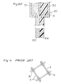
- the diameter of a resulting conventional metallic fiber F' is greater than that of the metallic fiber (F). This is because according to the conventional art, the organic fibers are metal-plated. Further, because the organic fibers are removed from the conventional metallic fiber F', a cavity (C) is generated therein. Thus, an active substance cannot be applied to the cavity (C) .
- the diameter of each of the metallic fibers (F) is 20 ⁇ m in average, whereas in the case of the conventional metallic fiber F' shown in Fig. 5B, the diameter thereof is 30 ⁇ m in average.
- the volume of each of the metallic fibers (F) is smaller by 55.6% than that of the conventional metallic fiber F'.
- the fiber density of the present invention is equal to that of the conventional one.
- the percentage of pores is 93% in the conventional porous metallic sheet, the percentage of pores is 96.9% in the porous metallic sheet of the present invention.
- the percentage of pores is 96% in the conventional porous metallic sheet, it is 98.2% in the porous metallic sheet of the present invention. That is, the percentage of pores of the porous metallic sheet of the present invention is greater than that of the conventional porous metallic sheet.
- the entire area of pores of the present invention to which an active substance can be applied is equal to that of the conventional porous metallic sheet, the porous metallic sheet has the metallic fibers (F) 2.25 times as great as the conventional porous metallic sheet per area. That is, as shown in Fig.
- the weight of metal to be used per area to form the porous metallic sheet of the present invention is equal to that to be used per area to form the conventional porous metallic sheet, the former is allowed to have more metallic fibers per area than the latter by 1.75 times as large as that of the latter, without decreasing the per-centage of pores.
- the porous metallic sheet according to the present invention has a higher conductivity than the conventional one, thus allowing a battery to have a more favorable characteristic than the conventional one. Supposing that the same number of metallic fibers is used per centiare to form the porous metallic sheet of the present invention and the conventional one, 420g is required per area in the case of the latter, whereas 240g is required in the case of the former.
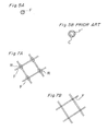
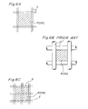
- a conventional problem of a resin lump formed at connection points of the metallic fibers (F) as shown in Fig. 16 is described. Even though resin is collected at the connection point of the metallic fibers (F) shown in Fig. 7A, it is burnt out during a resin binder removal process and a wintering process. Consequently, as shown in Fig. 7B, the resin lump disappears from the connection point. Accordingly, the diameter of the metallic fibers (F) can be prevented from becoming partly larger and thus the percentage of pores can be prevented from being reduced.
- the metallic fibers (F) are solid and continuous, they have a strength 1.5 - 3 times higher than the conventional metallic fibers formed by electrically plating organic fibers. Accordingly, in applying an active substance into pores, the porous metallic sheet 40 can be drawn at a great force. Thus, the active substance can be applied to the pores at a high speed.
- the sheet having a nonwoven porous structure is formed by intertwining the solid metallic fibers with each other, the metallic fibers (F) is allowed to be present uniformly on the peripheral surface and the inner peripheral thereof, whereas in the case of the conventional metallic porous sheet formed by electrically plating organic fibers, a large amount of metal is deposited on the peripheral surface of the sheet and a small amount of metal is deposited in the inner of the sheet. Therefore, the porous metallic sheet of the present invention is capable of improving the performance of a battery.
- the thickness of the porous metal-lic sheet can be set to as large as 3.3mm-5mm.
- the active sub-stance can be applied to the porous metallic sheet 40 consisting of the metallic fibers (F) with high efficiency.
- the discharge ports 51 for extruding the mixture (M) comprising the resin binder and metallic powder therefrom are arranged in parallel with each other in the nozzle body 20 of the spinning nozzle 16.
- the mixture (M) contains a large amount of metallic powder and thus when it is not easy to extrude the mixture (M) from the discharge ports 51, it is preferable to use the nozzle body 20 shown in Figs. 8B through 8D to form the mixture (M) into compound metallic fibers.
- the nozzle body 20 shown in Fig. 8B has the discharge port 51 for discharging the mixture (M) at the center thereof and a discharge port 52 for discharging only resin in the periphery of the discharge port 51.
- the mixture (M) extruded from the center of the nozzle body 20 forms a core 60 while the resin (R) extruded from the periphery of the center of the nozzle body 20 forms a sheath 61. That is, the mixture (M) is extruded from the nozzle body 20 as a compound metallic fiber consisting of the core 60 and the sheath 61 surrounding the core 60.
- the sheath 61 of the compound metallic fiber thus formed serves as adhesive agent in forming the mixture (M) into the sheet having a nonwoven porous structure by vibrating the net conveyor 33 widthwise.
- the sheath 61 is burnt out during a resin binder-removal and a sintering process, the diameter of the metallic fibers can be prevented from becoming great.
- the nozzle body 20 shown in Fig. 8C has a large number of discharge ports 51, for discharging the mixture (M), at predetermined intervals inside the discharge port 52 having a large diameter.
- the mixture (M) extruded from the discharge ports 51 forms the cores 60, and the resin (R) is extruded between the cores 60.
- the mixture (M) is extruded from the nozzle body 20 as a compound metallic fiber consisting of a resin portion 62 and a plurality of scattered cores 60 surrounded with the resin portion 62.
- the cores 60 are connected to each other during the resin binder-removal and sintering processes. As a result, each metallic fiber has a great surface area.
- the resin portion 62 made of polyester is dissolved in an alkaline solution to remove polyester, the metallic fiber can be composed of small diameter-metallic fibers separated from each other.
- the nozzle body 20 shown in Fig. 8D has the discharge port 51, for discharging the mixture (M), at one side of thereof and a resin discharge port 53 at the other side thereof. Resin different from the resin binder contained in the mixture (M) is discharged from the resin discharge port 53.
- the mixture (M) is extruded from the discharge ports 51 and 53, with the mixture (M) being in contact with the resin different from the resin binder contained in the mixture (M) to form a compound metallic fiber consisting of the core 60 of the mixture (M) connected with a resin portion 64 in a bimetallic state.
- the contraction coefficients of the core 60 and the resin portion 64 are different from each other. Therefore, when they are cooled in the cooling cylinder 21, the compound metallic fiber is curled. That is, the compound metallic fiber can be curved without using the crimpers 30 of suction drum type
- metallic powder and powdered resin binder are kneaded into filaments, and then, the filaments are cut to pellets, and then, the pellets are heated to fuse the powdered resin binder.
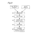
- the sheet having a nonwoven porous structure after the sheet having a nonwoven porous structure is formed, it is burnt out to remove the resin binder and the metallic powder is sintered. But it is possible to omit the burning out process at step #6 and the sintering process at step #7 as necessary, as shown in Fig. 9. If the metallic powder is mixed at high percentages, for example, 95 ⁇ - 97 ⁇ with the resin binder, it is unnecessary to burn out the sheet having a nonwoven porous structure to remove the resin binder.
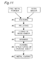
- the sheet having a nonwoven porous structure may be electrically plated at step #6 and then, the resin binder may be burnt out at step #7, and then, metallic powder may be sintered at step #8.
- the sheet having a nonwoven porous structure may be plated.
- metallic fibers of the sheet having a nonwoven porous structure are solid, a much smaller amount of metal is used to plate it compared with the conventional electrical plating method. Thus, a much smaller of electric power is consumed in plating the sheet having a nonwoven porous structure.
- the kind of metallic powder to be mixed with the powdered resin binder is not limited to one, but a plurality of kinds of metallic powders may be mixed with the resin binder so as to form compound metallic fibers.
- the method of bending the continuous metallic fibers formed by using the spinning nozzle and then transporting them to the net conveyor can be adopted when a porous fiber sheet or a three-dimensional net-shaped sheet having a porous structure is formed of metallic fibers.
- the continuous metallic fibers (F) may be woven in a mesh configuration to form a mesh sheet as shown in Fig. 12.
- wet nonwoven sheet-producing method of dispersing the short metallic fibers in water or water containing adhesive agent and collecting them with a net so as to form the sheet having a nonwoven porous structure.
- melt-blow nonwoven sheet-producing method of applying heated gas to the metallic fibers so as to draw and cut them to short fibers and then directly accumulating the short fibers on the conveyor so as to form the sheet having a nonwoven porous structure.
- span bonding method of applying air to the metallic fibers so as to draw them, accumulating them on the conveyor directly to form a web consisting of continuous metallic fibers, and bonding fibers of the web to each other with adhesive agent.
- porous metallic sheet 40 made of metallic powder is laminated one on the other to form a porous metallic sheet 100 to be used as a substrate of a battery electrode as shown in Fig. 13A.
- the porous metallic sheet 40 has a porous fibrous structure having a nonwoven sheet, a woven sheet, knitted sheet, a felt sheet, a screen-shaped sheet, an expanded sheet, a net-shaped sheet; and a three-dimensional net-shaped structure having a foamed sheet, a spongelike sheet, a honeycomb-shaped sheet.
- porous metallic sheet 100 it is possible to overlay a conductive metallic foil 101 having a plurality of pores 101a formed thereon on the porous metallic sheet 40 to form a porous metallic sheet 100'. Further, as shown in Fig. 13C, it is possible to form a porous metallic sheet 100" by laminating the porous metallic sheet 40 and a porous metallic sheet 102 formed by plating foamed, mesh or nonwoven sheets made of resin and then burning out resin binder and sintering metallic powder.
- an active substance is applied to the porous metallic sheets 40 of the first and second embodiment, 100, 100' or 100" of the further embodiment so as to form an electrode plate of a battery.
- the active substance is applied to the porous metallic sheet formed in the process of steps #1 through #7 of Fig. 1 showing the first embodiment.
- the active substance may be applied to the porous metallic sheet after performing the operation of the final process shown in Figs. 9, 10, and 11 showing the modifications of the first embodiment, after forming the porous metallic sheet by overlaying the porous metallic sheets 100, 100' or 100" on the porous metallic sheet 40.
- the active substance is applied to the nonwoven porous metallic sheet consisting of nickel fibers composed of nickel powder while the porous metallic sheet is being continuously drawn, so that an electrode of a nickel hydrogen battery is formed.
- paste of an active sub-stance was applied to a nonwoven porous metallic sheet made of nickel.
- the paste was obtained by kneading a mixture of 100 parts by weight of nickel hydroxide powder, 10 parts by weight of cobalt powder, 0.2 parts by weight of methyl cellulose used as adhesive agent, and 20 parts by weight of water. After the paste is dried, it is molded under pressure to form a positive electrode plate of a nickel hydrogen battery having a thickness of 0.5mm.
- paste of an active substance was applied to a sheet having a three-dimensional net-shaped structure made of nickel.
- the paste was obtained by kneading a mixture of 90 parts by weight of nickel hydroxide, 10 parts by weight of cobalt oxide, 0.4 parts by weight of carboxyl methyl cellulose, and 43 parts by weight of water. After the paste is dried, it is rolled by a roller press to form a positive electrode plate of a nickel cadmium battery having a thickness of 0.6mm.
- paste of an active sub-stance was applied to the three-dimensional net-shaped sheet made of nickel.
- the paste was obtained by kneading a mixture of 90 parts by weight of cadmium oxide, 10 parts by weight of nickel powder, 2.8 parts by weight of polyethylene powder, and 2.5 parts by weight of polytetrafluoroethylene, and organic solvent. After the paste is dried, it is molded under pressure form a negative electrode plate of a nickel cadmium battery having a thickness of 0.45mm.
- the diameter of metallic powder is as small as 0.1-5 ⁇ m.
- the metallic powder mixed with fused resin binder can be extruded from the spinning nozzle to form the mixture into fibers.
- the diameters of the fibers thus formed are as small as 1.0 ⁇ m-100 ⁇ m, the porous metallic sheet formed of the fibers has an improved percentage of pores and further, the area of one pore of the porous metallic sheet of the present invention is smaller area than that of one pore of the conventional porous metallic sheet, supposing that the percentage of pores of the former is the same as that of the latter.
- the former has a higher conductivity than the latter.
- the porous metallic sheet made of the fibers is allowed to have a high tension and thus the active substance can be applied to the porous metallic sheet at a high speed.
- porous metallic sheet It is possible to use various kinds of metals to form the porous metallic sheet in order to allow it to have a feature of each of the metals used. Further, a mixture of various kinds of metallic powders may be used to form fibers to allow the porous metallic sheet to have various characteristics which cannot be provided by the porous metallic sheet consisting of fibers made of only one kind of metal.
- the convex formed on the supporter is pyramidal as shown in Figs. 15B and 15C.
- the web (B) on the convex 208 flows downward from the upper end of the convex 208 and forced to drop to the upper surface of the supporter 207 in the periphery of the convex 208 along the peripheral surface of the convex 208, thus forming the annular web (B) in the periphery of the lower end of the convex 208.
- through-holes 218 corresponding to the sectional configuration of the lower end of the convex 208 is formed on the sheet (S).
- the convexes 208 are conic and formed at regular intervals, as shown in Fig. 15A, the circular through-holes 218 are formed at regular intervals on the sheet (S).
- the convexes 208 are pyramidal as shown in Figs. 15B and 15C, the rhombic or square through-hole 218 are formed on the porous metallic sheet 220.
- the lath-shaped through-holes 218 or the net-shaped through-holes 218 are formed on the porous metallic sheet 220.
- the three-dimensional nonwoven porous metallic sheet 220 having the circular through-holes 218, the lath-shaped through-holes 218 or the net-shaped through-holes 218 has not only the through-holes 218 formed therein at regular intervals, but also a great number of fine pores at the portion except for the through-holes 218.
- the porous metallic sheet to be used as the electrode substrate of a battery in accordance with the present invention has the following effects.
Landscapes
- Chemical & Material Sciences (AREA)
- Chemical Kinetics & Catalysis (AREA)
- General Chemical & Material Sciences (AREA)
- Electrochemistry (AREA)
- Engineering & Computer Science (AREA)
- Manufacturing & Machinery (AREA)
- Mechanical Engineering (AREA)
- Nanotechnology (AREA)
- Inorganic Chemistry (AREA)
- Life Sciences & Earth Sciences (AREA)
- Geology (AREA)
- Cell Electrode Carriers And Collectors (AREA)
- Battery Electrode And Active Subsutance (AREA)
- Powder Metallurgy (AREA)
Claims (10)
- Feuille métallique poreuse destinée à être utilisée comme substrat d'électrode d'une cellule électrochimique, possédant une structure fibreuse poreuse ou une structure de réseau tridimensionnel dans laquelle un entrelacement entourant des pores de la structure fibreuse poreuse ou ceux de la structure de réseau tridimensionnel est formé de fibres métalliques constituées de poudre métallique, dans laquelle la structure fibreuse poreuse ou la structure en forme de réseau tridimensionnel a des pores fins et un grand nombre de trous débouchants formés à l'intérieur.
- Feuille métallique poreuse destinée à être utilisée comme substrat d'électrode d'une cellule électrochimique, ayant une structure fibreuse poreuse ou une structure en forme de réseau tridimensionnel dans laquelle un entrelacement entourant des pores de la structure fibreuse poreuse ou ceux de la structure en forme de réseau tridimensionnel est formé de fibres métalliques de poudre métallique, dans laquelle la feuille métallique poreuse constituée de fibres métalliques est recouverte d'une ou deux feuilles choisies dans le groupe constitué par une feuille métallique poreuse formée d'une substance organique revêtue ou d'une substance minérale, et une feuille métallique conductrice ayant plusieurs trous formés à l'intérieur.
- Feuille métallique poreuse selon la revendication 1 ou 2, dans laquelle les fibres métalliques sont constituées de courtes fibres ayant chacune une longueur comprise entre 1 et 60 mm.
- Feuille métallique poreuse selon l'une quelconque des revendications 1 à 3, dans laquelle la structure fibreuse poreuse est constituée d'une feuille non tissée, d'une feuille tissée, d'une feuille tricotée, d'une feuille de feutre, d'une feuille en forme d'écran, d'une feuille déployée ou d'une feuille en forme de réseau, et la structure en forme de réseau tridimensionnel est constituée d'une feuille de mousse, d'une feuille analogue à une éponge ou d'une feuille en forme de nid d'abeilles.
- Feuille métallique poreuse selon la revendication 1, dans laquelle les trous débouchants sont circulaires, rectangulaires ou en losange, si bien que la feuille métallique poreuse peut être une feuille analogue à une feuille poinçonnée, une feuille en forme de réseau ou une feuille en forme de lattes.
- Feuille métallique selon la revendication 1 ou 5, dans laquelle une partie en forme de courroie destinée à être utilisée comme fil de connexion d'une plaque d'électrode est réalisée dans une région dans laquelle les trous débouchants ne sont pas formés.
- Feuille métallique poreuse selon l'une quelconque des revendications 1 à 6, dans laquelle des surfaces des fibres métalliques ont subi une électrodéposition.
- Feuille métallique poreuse selon la revendication 1, dans laquelle plusieurs feuilles métalliques poreuses ayant la même configuration ou plusieurs feuilles métalliques poreuses ayant des configurations différentes sont stratifiées les unes sur les autres.
- Plaque d'électrode de cellule électrochimique formée par application d'une substance active à la feuille métallique poreuse selon l'une quelconque des revendications 1 à 8.
- Plaque d'électrode de cellule électrochimique selon la revendication 9, dans laquelle l'électrode de cellule est utilisée comme plaque d'électrode d'une cellule électrochimique nickel-hydrogène, d'une cellule électrochimique nickel-cadmium, d'un accumulateur au lithium ou d'une pile au lithium.
Applications Claiming Priority (3)
| Application Number | Priority Date | Filing Date | Title |
|---|---|---|---|
| JP29328694 | 1994-11-28 | ||
| JP293286/94 | 1994-11-28 | ||
| JP29328694 | 1994-11-28 |
Publications (3)
| Publication Number | Publication Date |
|---|---|
| EP0717457A2 EP0717457A2 (fr) | 1996-06-19 |
| EP0717457A3 EP0717457A3 (fr) | 1997-01-08 |
| EP0717457B1 true EP0717457B1 (fr) | 2000-02-02 |
Family
ID=17792872
Family Applications (1)
| Application Number | Title | Priority Date | Filing Date |
|---|---|---|---|
| EP95118659A Expired - Lifetime EP0717457B1 (fr) | 1994-11-28 | 1995-11-27 | Feuille poreuse métallique pour un substrat d'électrode de batterie, et méthode de production |
Country Status (8)
| Country | Link |
|---|---|
| US (1) | US6110417A (fr) |
| EP (1) | EP0717457B1 (fr) |
| JP (2) | JPH08213026A (fr) |
| KR (1) | KR100226040B1 (fr) |
| CN (1) | CN1127433A (fr) |
| CA (1) | CA2163819C (fr) |
| DE (1) | DE69514900T2 (fr) |
| TW (1) | TW492214B (fr) |
Families Citing this family (63)
| Publication number | Priority date | Publication date | Assignee | Title |
|---|---|---|---|---|
| US6051117A (en) * | 1996-12-12 | 2000-04-18 | Eltech Systems, Corp. | Reticulated metal article combining small pores with large apertures |
| FR2762142B1 (fr) * | 1997-04-11 | 1999-07-02 | Guy Leichle | Nouveau produit utilisable comme support d'electrode de batterie, du type a structure textile |
| US6240616B1 (en) | 1997-04-15 | 2001-06-05 | Advanced Cardiovascular Systems, Inc. | Method of manufacturing a medicated porous metal prosthesis |
| US10028851B2 (en) | 1997-04-15 | 2018-07-24 | Advanced Cardiovascular Systems, Inc. | Coatings for controlling erosion of a substrate of an implantable medical device |
| DE69817592T2 (de) * | 1997-06-27 | 2004-07-01 | Lg Chemical Ltd. | Lithium-ionen sekundärbatterie und verfahren zu deren herstellung |
| CN1064781C (zh) * | 1997-12-11 | 2001-04-18 | 西北有色金属研究院 | 一种镍纤维毡电极及其制备方法 |
| DE60033076T2 (de) * | 1999-04-16 | 2007-08-30 | Matsushita Electric Industrial Co., Ltd., Kadoma | Anodische Elektrode für Elektrolytkondensator und Verfahren zu ihrer Herstellung |
| JP4711479B2 (ja) * | 1999-10-27 | 2011-06-29 | 株式会社イノアックコーポレーション | リチウムイオン二次電池の電極用ハニカム構造集電体、リチウムイオン二次電池の電極及びリチウムイオン二次電池の電極用ハニカム構造集電体の製造方法 |
| AT408288B (de) * | 2000-05-10 | 2001-10-25 | Funktionswerkstoffe Forschungs | Mehrschichtige elektrode |
| CA2422212A1 (fr) * | 2000-09-14 | 2003-03-13 | Ulf Zum Felde | Couche ou feuille pouvant etre activee de maniere electrochimique |
| US6805898B1 (en) | 2000-09-28 | 2004-10-19 | Advanced Cardiovascular Systems, Inc. | Surface features of an implantable medical device |
| EP1199122B1 (fr) * | 2000-10-16 | 2004-03-03 | Future Metal Co., Ltd. | Procédé de préparation de fibres métalliques |
| KR100378007B1 (ko) * | 2000-11-22 | 2003-03-29 | 삼성에스디아이 주식회사 | 리튬-황 전지용 양극 및 그를 포함하는 리튬-황 전지 |
| AT410860B (de) * | 2001-01-19 | 2003-08-25 | Funktionswerkstoffe Forschungs | Elektrode einer elektrochemischen anordnung |
| EP1436835A2 (fr) * | 2001-10-18 | 2004-07-14 | Honeywell International, Inc. | Interface thermique electriquement conductrice |
| US20030170543A1 (en) * | 2002-02-26 | 2003-09-11 | Alltrista Zinc Products Company, L.P. | Zinc fibers, zinc anodes and methods of making zinc fibers |
| US10629947B2 (en) | 2008-08-05 | 2020-04-21 | Sion Power Corporation | Electrochemical cell |
| EP1753565B1 (fr) * | 2004-04-15 | 2010-01-27 | NV Bekaert SA | Procede pour produire un corps fritte a partir de fibres metalliques |
| CN100428539C (zh) * | 2004-08-18 | 2008-10-22 | 马志刚 | 一种镍氢电池负极板真空烧结方法 |
| US7629071B2 (en) * | 2004-09-29 | 2009-12-08 | Giner Electrochemical Systems, Llc | Gas diffusion electrode and method of making the same |
| KR100562043B1 (ko) * | 2005-07-27 | 2006-03-17 | 한국화학연구원 | 금속 분리막의 제조방법 |
| FR2901641B1 (fr) * | 2006-05-24 | 2009-04-24 | Electricite De France | Electrode textile et accumulateur contenant une telle electrode |
| KR101601992B1 (ko) * | 2008-01-08 | 2016-03-09 | 시온 파워 코퍼레이션 | 다공성 전극 및 관련 방법 |
| EP2409349A4 (fr) * | 2009-03-19 | 2013-05-01 | Sion Power Corp | Cathode pour batterie au lithium |
| US20110206992A1 (en) * | 2009-08-28 | 2011-08-25 | Sion Power Corporation | Porous structures for energy storage devices |
| US20110070491A1 (en) | 2009-08-28 | 2011-03-24 | Sion Power Corporation | Electrochemical cells comprising porous structures comprising sulfur |
| PH12012501073A1 (en) * | 2009-12-04 | 2014-06-18 | Mitsui Mining & Smelting Co Ltd | Porous metal foil and production method therefor |
| JP5974424B2 (ja) * | 2010-11-30 | 2016-08-23 | 三菱マテリアル株式会社 | 電気二重層キャパシタ用電極およびこれを用いた電気二重層キャパシタ |
| JP2012186142A (ja) * | 2011-02-18 | 2012-09-27 | Sumitomo Electric Ind Ltd | 電気化学デバイス用電極およびその製造方法 |
| FR2973949B1 (fr) * | 2011-04-06 | 2013-10-11 | Electricite De France | Precurseur d'accumulateur lithium-ion a electrode sacrificielle de lithium et electrode textile negative a conversion |
| KR101337488B1 (ko) * | 2011-05-26 | 2013-12-05 | 광주과학기술원 | 리튬 이차전지용 전극, 이의 제조방법 및 리튬 이차전지 |
| US9548492B2 (en) | 2011-06-17 | 2017-01-17 | Sion Power Corporation | Plating technique for electrode |
| CN102290582A (zh) * | 2011-06-20 | 2011-12-21 | 华南理工大学 | 一种用于燃料电池双极板的不锈钢纤维毡及其制造方法 |
| KR101905233B1 (ko) | 2011-10-13 | 2018-10-05 | 시온 파워 코퍼레이션 | 전극 구조물 및 그의 제조 방법 |
| WO2013119223A1 (fr) * | 2012-02-08 | 2013-08-15 | Empire Technology Development Llc | Electrode souple, extensible et à motif avec un substrat non conducteur |
| WO2013123131A1 (fr) | 2012-02-14 | 2013-08-22 | Sion Power Corporation | Structure d'électrode destinée à une cellule électrochimique |
| KR101991149B1 (ko) | 2012-12-19 | 2019-06-19 | 시온 파워 코퍼레이션 | 전극 구조물 및 그의 제조 방법 |
| WO2014118080A1 (fr) * | 2013-02-04 | 2014-08-07 | Nv Bekaert Sa | Tube de trempe pour extrusion de fibres polymères |
| US12261284B2 (en) | 2013-03-15 | 2025-03-25 | Sion Power Corporation | Protective structures for electrodes |
| KR101586251B1 (ko) * | 2013-06-24 | 2016-01-18 | 주식회사 제낙스 | 이차 전지용 집전체 및 이를 이용한 전극 |
| WO2015166030A1 (fr) | 2014-05-01 | 2015-11-05 | Basf Se | Procédés de fabrication d'électrode et articles associés |
| US11038165B2 (en) | 2014-05-29 | 2021-06-15 | Sila Nanotechnologies, Inc. | Ion permeable composite current collectors for metal-ion batteries and cell design using the same |
| US20170005338A1 (en) * | 2015-07-01 | 2017-01-05 | Giga Amps UK Limited | Electrical storage batteries |
| CN105057674A (zh) * | 2015-08-28 | 2015-11-18 | 西北有色金属研究院 | 一种不锈钢纤维烧结毡的制备方法 |
| JP6917161B2 (ja) | 2016-03-03 | 2021-08-11 | 株式会社半導体エネルギー研究所 | リチウムイオン二次電池用の正極活物質、二次電池、電池制御ユニットおよび電子機器 |
| CN109806664B (zh) * | 2017-11-22 | 2022-03-04 | 辽宁省轻工科学研究院有限公司 | 一种耐1000℃金属高温过滤器的制备方法 |
| CN108400337B (zh) * | 2018-01-09 | 2020-07-10 | 浙江南都电源动力股份有限公司 | 锂离子电池用集流体和锂离子电池 |
| CN109097842B (zh) * | 2018-08-15 | 2021-04-20 | 湖南工程学院 | 一种聚合物静电纺丝接收网帘的制备方法 |
| CN109128171B (zh) * | 2018-11-07 | 2023-09-19 | 沈阳航空航天大学 | 一种细化增材制造钛合金晶粒的装置 |
| KR102052297B1 (ko) * | 2019-01-14 | 2020-01-08 | 주식회사 제낙스 | 리튬 이차 전지용 전극, 이를 포함하는 리튬 이차 전지 및 이의 제조 방법 |
| CN109860603B (zh) * | 2019-01-21 | 2022-01-28 | 珠海冠宇电池股份有限公司 | 锂电池极片及其制备方法及锂电池 |
| WO2021192669A1 (fr) * | 2020-03-27 | 2021-09-30 | 株式会社巴川製紙所 | Corps moulé en fibres métalliques, unité de régulation de température et procédé de fabrication de corps moulé en fibres métalliques |
| CN111540607B (zh) * | 2020-05-29 | 2022-01-14 | 东莞东阳光科研发有限公司 | 电极结构材料及制备电极结构材料的方法、电解电容器 |
| CN111644599B (zh) * | 2020-06-10 | 2022-04-12 | 广东科学技术职业学院 | 一种三维连续网络结构石墨/铸钢复合材料及其制备方法 |
| DE102020122287A1 (de) | 2020-08-26 | 2022-03-03 | Audi Aktiengesellschaft | Batteriezelle, Fahrzeugbatterie, Kraftfahrzeug und Verfahren zum Herstellen eines Trägerelements für eine Elektrode einer Batteriezelle |
| CN113249662B (zh) * | 2021-04-25 | 2022-04-12 | 上海懋业铁合金有限公司 | 一种内嵌网芯式金属粉末冶金工艺 |
| CN215451469U (zh) * | 2021-07-15 | 2022-01-07 | 比亚迪股份有限公司 | 一种干法电池极片 |
| CN114361461B (zh) * | 2022-01-10 | 2024-01-16 | 上海恩捷新材料科技有限公司 | 柔性集流体芯层、集流体、极片和电池及其制备方法 |
| CN115890151B (zh) * | 2022-11-29 | 2026-02-27 | 天津津航技术物理研究所 | 一种新型加速度计敏感结构电极板的精密制造方法 |
| WO2024262444A1 (fr) * | 2023-06-23 | 2024-12-26 | パナソニックIpマネジメント株式会社 | Procédé de fabrication d'électrode d'électrolyse d'eau |
| CN117483769A (zh) * | 2023-11-24 | 2024-02-02 | 艾氢技术(苏州)有限公司 | 一种利于化学反应的金属颗粒块制作方法及金属颗粒块 |
| CN118315599B (zh) * | 2024-04-02 | 2024-12-17 | 浙江天能电池(江苏)有限公司 | 一种铅酸蓄电池交扣铅网及其制备方法 |
| CN119481347B (zh) * | 2025-01-14 | 2025-05-27 | 宁德时代新能源科技股份有限公司 | 卷绕机、电池生产设备和卷绕方法 |
Family Cites Families (16)
| Publication number | Priority date | Publication date | Assignee | Title |
|---|---|---|---|---|
| US3895960A (en) * | 1970-08-27 | 1975-07-22 | Westinghouse Electric Corp | Diffusion-bonded battery electrode plaques |
| US3702019A (en) * | 1971-04-13 | 1972-11-07 | Westinghouse Electric Corp | Method of making diffusion bonded battery plaques |
| US3835514A (en) * | 1971-05-17 | 1974-09-17 | Westinghouse Electric Corp | Method of making laminated diffusion bonded battery plaques |
| GB1451677A (en) * | 1973-06-07 | 1976-10-06 | Battelle Memorial Institute | Method of manufacturing positive nickel hydroxide electrodes |
| DE2720278C2 (de) * | 1977-05-05 | 1985-03-21 | Nippon Seisen Co., Ltd., Hirakata, Osaka | Verfahren zur Herstellung eines verstärkten Metallfilters |
| US4222977A (en) * | 1978-05-16 | 1980-09-16 | Monsanto Company | Process to produce inorganic hollow fibers |
| JPS56145668A (en) * | 1980-04-11 | 1981-11-12 | Yuasa Battery Co Ltd | Pasted positive plate for alkaline storage battery |
| JPS59163754A (ja) * | 1983-03-08 | 1984-09-14 | Yuasa Battery Co Ltd | アルカリ蓄電池用ペ−スト式正極板 |
| US4769212A (en) * | 1985-03-29 | 1988-09-06 | Hitachi Metals, Ltd | Process for producing metallic sintered parts |
| JPH01320762A (ja) * | 1988-06-22 | 1989-12-26 | Toshiba Corp | アルカリ蓄電池用ニッケル極 |
| US5294319A (en) * | 1989-12-26 | 1994-03-15 | Olin Corporation | High surface area electrode structures for electrochemical processes |
| CA2073575A1 (fr) * | 1991-07-19 | 1993-01-20 | Paul C. Koehler | Article en metal plisse |
| JPH0525509A (ja) * | 1991-07-20 | 1993-02-02 | Daido Steel Co Ltd | 金属線材の押出し製造法 |
| US5584109A (en) * | 1994-06-22 | 1996-12-17 | Memtec America Corp. | Method of making a battery plate |
| JPH08162107A (ja) * | 1994-12-08 | 1996-06-21 | Bridgestone Metalpha Kk | アルカリ二次電池用ニッケル電極の基板 |
| US5766789A (en) * | 1995-09-29 | 1998-06-16 | Energetics Systems Corporation | Electrical energy devices |
-
1995
- 1995-11-14 JP JP7295734A patent/JPH08213026A/ja not_active Abandoned
- 1995-11-24 TW TW086106586A patent/TW492214B/zh not_active IP Right Cessation
- 1995-11-27 EP EP95118659A patent/EP0717457B1/fr not_active Expired - Lifetime
- 1995-11-27 DE DE69514900T patent/DE69514900T2/de not_active Expired - Fee Related
- 1995-11-27 CA CA002163819A patent/CA2163819C/fr not_active Expired - Fee Related
- 1995-11-28 KR KR1019950044143A patent/KR100226040B1/ko not_active Expired - Fee Related
- 1995-11-28 CN CN95119623A patent/CN1127433A/zh active Pending
-
1999
- 1999-02-26 US US09/258,866 patent/US6110417A/en not_active Expired - Fee Related
-
2002
- 2002-11-14 JP JP2002331258A patent/JP2003193110A/ja not_active Ceased
Also Published As
| Publication number | Publication date |
|---|---|
| JPH08213026A (ja) | 1996-08-20 |
| EP0717457A2 (fr) | 1996-06-19 |
| CA2163819A1 (fr) | 1996-05-29 |
| TW492214B (en) | 2002-06-21 |
| CA2163819C (fr) | 2000-12-26 |
| JP2003193110A (ja) | 2003-07-09 |
| DE69514900D1 (de) | 2000-03-09 |
| US6110417A (en) | 2000-08-29 |
| CN1127433A (zh) | 1996-07-24 |
| DE69514900T2 (de) | 2000-10-05 |
| KR960019831A (ko) | 1996-06-17 |
| KR100226040B1 (ko) | 1999-10-15 |
| EP0717457A3 (fr) | 1997-01-08 |
Similar Documents
| Publication | Publication Date | Title |
|---|---|---|
| US6110417A (en) | Porous metallic sheet used as an electrode substrate of a battery and method of manufacturing the porous material sheet | |
| CN101091272B (zh) | 固体多孔锌电极及其制造方法 | |
| CN1090825C (zh) | 能提供导线的多孔金属片材和制备该片材的方法 | |
| EP0802005B1 (fr) | Procédé de préparation d'une tôle métallique poreuse dont les pores forment une structure | |
| KR101293276B1 (ko) | 다공성 폴리머 웹 집전체 및 그의 제조방법 | |
| US6436580B1 (en) | Method of manufacturing porous sheet, porous metal sheet manufactured by method, and electrode for battery | |
| CN1130785C (zh) | 电池电极用基板的制造方法及电池电极用基板 | |
| JPH09143510A (ja) | 電池電極基板用金属繊維多孔体、電池電極板およびその製造方法 | |
| WO1998004374A1 (fr) | Corps metallique poreux et son procede de production | |
| JPH0752647B2 (ja) | 電池用電極とその製造方法 | |
| JPH10310806A (ja) | 金属多孔体の製造方法、該方法により製造された金属多孔体及び電池用電極 | |
| EP0813261A2 (fr) | Feuille métallique pour substrat d'électrode d'un boîtier de batterie | |
| KR100242814B1 (ko) | 전지전극기판 | |
| CA2254551C (fr) | Methode de fabrication d'une feuille metallique poreuse pour utilisation en tant que support d'electrode de batterie | |
| JPH08321303A (ja) | アルカリ二次電池用の電極 | |
| JPH08329953A (ja) | ニッケルめっき不織布電極基板の製造方法 | |
| JPH06338329A (ja) | ニッケルめっき不織布電極基板の製造方法 | |
| JPH08203534A (ja) | ニッケルめっき不織布電極基板の製造方法 | |
| JPH08250125A (ja) | ニッケルめっき不織布電極基板 | |
| JP2001266832A (ja) | アルカリ電池用セパレータ | |
| JPH08329952A (ja) | 多孔性ニッケルめっき電極基板の評価方法及びこれを用いた多孔性ニッケルめっき電極基板 | |
| JPH10144321A (ja) | 金属多孔体の製造方法および金属多孔体を用いた電池 | |
| JPH10189001A (ja) | 二次電池の正極の製造方法 | |
| JPH05325980A (ja) | 三次元網目状基体電極 | |
| HK1028680A (en) | Alkaline storage battery and manufacturing method of the same |
Legal Events
| Date | Code | Title | Description |
|---|---|---|---|
| PUAI | Public reference made under article 153(3) epc to a published international application that has entered the european phase |
Free format text: ORIGINAL CODE: 0009012 |
|
| 17P | Request for examination filed |
Effective date: 19951127 |
|
| AK | Designated contracting states |
Kind code of ref document: A2 Designated state(s): BE CH DE ES FR GB IT LI NL SE |
|
| PUAL | Search report despatched |
Free format text: ORIGINAL CODE: 0009013 |
|
| AK | Designated contracting states |
Kind code of ref document: A3 Designated state(s): BE CH DE ES FR GB IT LI NL SE |
|
| 17Q | First examination report despatched |
Effective date: 19971112 |
|
| GRAG | Despatch of communication of intention to grant |
Free format text: ORIGINAL CODE: EPIDOS AGRA |
|
| GRAG | Despatch of communication of intention to grant |
Free format text: ORIGINAL CODE: EPIDOS AGRA |
|
| GRAH | Despatch of communication of intention to grant a patent |
Free format text: ORIGINAL CODE: EPIDOS IGRA |
|
| GRAH | Despatch of communication of intention to grant a patent |
Free format text: ORIGINAL CODE: EPIDOS IGRA |
|
| GRAA | (expected) grant |
Free format text: ORIGINAL CODE: 0009210 |
|
| AK | Designated contracting states |
Kind code of ref document: B1 Designated state(s): BE CH DE ES FR GB IT LI NL SE |
|
| PG25 | Lapsed in a contracting state [announced via postgrant information from national office to epo] |
Ref country code: NL Free format text: LAPSE BECAUSE OF FAILURE TO SUBMIT A TRANSLATION OF THE DESCRIPTION OR TO PAY THE FEE WITHIN THE PRESCRIBED TIME-LIMIT Effective date: 20000202 Ref country code: IT Free format text: LAPSE BECAUSE OF FAILURE TO SUBMIT A TRANSLATION OF THE DESCRIPTION OR TO PAY THE FEE WITHIN THE PRE;WARNING: LAPSES OF ITALIAN PATENTS WITH EFFECTIVE DATE BEFORE 2007 MAY HAVE OCCURRED AT ANY TIME BEFORE 2007. THE CORRECT EFFECTIVE DATE MAY BE DIFFERENT FROM THE ONE RECORDED.SCRIBED TIME-LIMIT Effective date: 20000202 Ref country code: ES Free format text: THE PATENT HAS BEEN ANNULLED BY A DECISION OF A NATIONAL AUTHORITY Effective date: 20000202 |
|
| REG | Reference to a national code |
Ref country code: CH Ref legal event code: EP |
|
| REF | Corresponds to: |
Ref document number: 69514900 Country of ref document: DE Date of ref document: 20000309 |
|
| REG | Reference to a national code |
Ref country code: CH Ref legal event code: NV Representative=s name: BOVARD AG PATENTANWAELTE |
|
| PG25 | Lapsed in a contracting state [announced via postgrant information from national office to epo] |
Ref country code: SE Free format text: LAPSE BECAUSE OF FAILURE TO SUBMIT A TRANSLATION OF THE DESCRIPTION OR TO PAY THE FEE WITHIN THE PRESCRIBED TIME-LIMIT Effective date: 20000502 |
|
| ET | Fr: translation filed | ||
| NLV1 | Nl: lapsed or annulled due to failure to fulfill the requirements of art. 29p and 29m of the patents act | ||
| PGFP | Annual fee paid to national office [announced via postgrant information from national office to epo] |
Ref country code: CH Payment date: 20001109 Year of fee payment: 6 |
|
| PLBE | No opposition filed within time limit |
Free format text: ORIGINAL CODE: 0009261 |
|
| STAA | Information on the status of an ep patent application or granted ep patent |
Free format text: STATUS: NO OPPOSITION FILED WITHIN TIME LIMIT |
|
| 26N | No opposition filed | ||
| PG25 | Lapsed in a contracting state [announced via postgrant information from national office to epo] |
Ref country code: LI Free format text: LAPSE BECAUSE OF NON-PAYMENT OF DUE FEES Effective date: 20011130 Ref country code: CH Free format text: LAPSE BECAUSE OF NON-PAYMENT OF DUE FEES Effective date: 20011130 |
|
| REG | Reference to a national code |
Ref country code: GB Ref legal event code: IF02 |
|
| REG | Reference to a national code |
Ref country code: CH Ref legal event code: PL |
|
| PGFP | Annual fee paid to national office [announced via postgrant information from national office to epo] |
Ref country code: FR Payment date: 20051018 Year of fee payment: 11 |
|
| PGFP | Annual fee paid to national office [announced via postgrant information from national office to epo] |
Ref country code: GB Payment date: 20051117 Year of fee payment: 11 |
|
| PGFP | Annual fee paid to national office [announced via postgrant information from national office to epo] |
Ref country code: DE Payment date: 20051124 Year of fee payment: 11 |
|
| PGFP | Annual fee paid to national office [announced via postgrant information from national office to epo] |
Ref country code: BE Payment date: 20051201 Year of fee payment: 11 |
|
| PG25 | Lapsed in a contracting state [announced via postgrant information from national office to epo] |
Ref country code: BE Free format text: LAPSE BECAUSE OF NON-PAYMENT OF DUE FEES Effective date: 20061130 |
|
| PG25 | Lapsed in a contracting state [announced via postgrant information from national office to epo] |
Ref country code: DE Free format text: LAPSE BECAUSE OF NON-PAYMENT OF DUE FEES Effective date: 20070601 |
|
| GBPC | Gb: european patent ceased through non-payment of renewal fee |
Effective date: 20061127 |
|
| REG | Reference to a national code |
Ref country code: FR Ref legal event code: ST Effective date: 20070731 |
|
| PG25 | Lapsed in a contracting state [announced via postgrant information from national office to epo] |
Ref country code: GB Free format text: LAPSE BECAUSE OF NON-PAYMENT OF DUE FEES Effective date: 20061127 |
|
| BERE | Be: lapsed |
Owner name: *KATAYAMA SPECIAL INDUSTRIES LTD Effective date: 20061130 |
|
| PG25 | Lapsed in a contracting state [announced via postgrant information from national office to epo] |
Ref country code: FR Free format text: LAPSE BECAUSE OF NON-PAYMENT OF DUE FEES Effective date: 20061130 |