EP0719965A2 - Lagerelement für Schalthebel - Google Patents
Lagerelement für Schalthebel Download PDFInfo
- Publication number
- EP0719965A2 EP0719965A2 EP95303803A EP95303803A EP0719965A2 EP 0719965 A2 EP0719965 A2 EP 0719965A2 EP 95303803 A EP95303803 A EP 95303803A EP 95303803 A EP95303803 A EP 95303803A EP 0719965 A2 EP0719965 A2 EP 0719965A2
- Authority
- EP
- European Patent Office
- Prior art keywords
- lever
- main
- fulcrum member
- change lever
- subsidiary
- Prior art date
- Legal status (The legal status is an assumption and is not a legal conclusion. Google has not performed a legal analysis and makes no representation as to the accuracy of the status listed.)
- Granted
Links
- 230000008859 change Effects 0.000 title claims abstract description 40
- 230000002093 peripheral effect Effects 0.000 claims abstract description 11
- 239000004519 grease Substances 0.000 claims description 33
- 230000033001 locomotion Effects 0.000 claims description 10
- 230000005540 biological transmission Effects 0.000 claims description 6
- 230000008878 coupling Effects 0.000 claims description 4
- 238000010168 coupling process Methods 0.000 claims description 4
- 238000005859 coupling reaction Methods 0.000 claims description 4
- 238000000465 moulding Methods 0.000 claims description 4
- 229920003002 synthetic resin Polymers 0.000 claims description 2
- 239000000057 synthetic resin Substances 0.000 claims description 2
- 210000000078 claw Anatomy 0.000 description 10
- 230000013011 mating Effects 0.000 description 6
- 229920005989 resin Polymers 0.000 description 5
- 239000011347 resin Substances 0.000 description 5
- 238000006073 displacement reaction Methods 0.000 description 4
- 238000005461 lubrication Methods 0.000 description 4
- 229910052751 metal Inorganic materials 0.000 description 3
- 239000002184 metal Substances 0.000 description 3
- 238000000034 method Methods 0.000 description 3
- 238000005520 cutting process Methods 0.000 description 2
- 238000004519 manufacturing process Methods 0.000 description 2
- 230000008569 process Effects 0.000 description 2
- 230000000717 retained effect Effects 0.000 description 2
- 229910000831 Steel Inorganic materials 0.000 description 1
- 239000004411 aluminium Substances 0.000 description 1
- 229910052782 aluminium Inorganic materials 0.000 description 1
- XAGFODPZIPBFFR-UHFFFAOYSA-N aluminium Chemical compound [Al] XAGFODPZIPBFFR-UHFFFAOYSA-N 0.000 description 1
- 230000006835 compression Effects 0.000 description 1
- 238000007906 compression Methods 0.000 description 1
- 230000006872 improvement Effects 0.000 description 1
- 230000004048 modification Effects 0.000 description 1
- 238000012986 modification Methods 0.000 description 1
- 238000005192 partition Methods 0.000 description 1
- 230000009467 reduction Effects 0.000 description 1
- 230000003014 reinforcing effect Effects 0.000 description 1
- 238000009751 slip forming Methods 0.000 description 1
- 239000010959 steel Substances 0.000 description 1
Images


Classifications
-
- F—MECHANICAL ENGINEERING; LIGHTING; HEATING; WEAPONS; BLASTING
- F16—ENGINEERING ELEMENTS AND UNITS; GENERAL MEASURES FOR PRODUCING AND MAINTAINING EFFECTIVE FUNCTIONING OF MACHINES OR INSTALLATIONS; THERMAL INSULATION IN GENERAL
- F16H—GEARING
- F16H59/00—Control inputs to control units of change-speed- or reversing-gearings for conveying rotary motion
- F16H59/02—Selector apparatus
- F16H59/04—Ratio selector apparatus
-
- F—MECHANICAL ENGINEERING; LIGHTING; HEATING; WEAPONS; BLASTING
- F16—ENGINEERING ELEMENTS AND UNITS; GENERAL MEASURES FOR PRODUCING AND MAINTAINING EFFECTIVE FUNCTIONING OF MACHINES OR INSTALLATIONS; THERMAL INSULATION IN GENERAL
- F16H—GEARING
- F16H61/00—Control functions within control units of change-speed- or reversing-gearings for conveying rotary motion ; Control of exclusively fluid gearing, friction gearing, gearings with endless flexible members or other particular types of gearing
- F16H61/26—Generation or transmission of movements for final actuating mechanisms
- F16H61/36—Generation or transmission of movements for final actuating mechanisms with at least one movement being transmitted by a cable
-
- B—PERFORMING OPERATIONS; TRANSPORTING
- B60—VEHICLES IN GENERAL
- B60K—ARRANGEMENT OR MOUNTING OF PROPULSION UNITS OR OF TRANSMISSIONS IN VEHICLES; ARRANGEMENT OR MOUNTING OF PLURAL DIVERSE PRIME-MOVERS IN VEHICLES; AUXILIARY DRIVES FOR VEHICLES; INSTRUMENTATION OR DASHBOARDS FOR VEHICLES; ARRANGEMENTS IN CONNECTION WITH COOLING, AIR INTAKE, GAS EXHAUST OR FUEL SUPPLY OF PROPULSION UNITS IN VEHICLES
- B60K20/00—Arrangement or mounting of change-speed gearing control devices in vehicles
- B60K20/02—Arrangement or mounting of change-speed gearing control devices in vehicles of initiating means
- B60K20/04—Arrangement or mounting of change-speed gearing control devices in vehicles of initiating means floor mounted
-
- F—MECHANICAL ENGINEERING; LIGHTING; HEATING; WEAPONS; BLASTING
- F16—ENGINEERING ELEMENTS AND UNITS; GENERAL MEASURES FOR PRODUCING AND MAINTAINING EFFECTIVE FUNCTIONING OF MACHINES OR INSTALLATIONS; THERMAL INSULATION IN GENERAL
- F16H—GEARING
- F16H59/00—Control inputs to control units of change-speed- or reversing-gearings for conveying rotary motion
- F16H59/02—Selector apparatus
- F16H2059/026—Details or special features of the selector casing or lever support
- F16H2059/0269—Ball joints or spherical bearings for supporting the lever
-
- F—MECHANICAL ENGINEERING; LIGHTING; HEATING; WEAPONS; BLASTING
- F16—ENGINEERING ELEMENTS AND UNITS; GENERAL MEASURES FOR PRODUCING AND MAINTAINING EFFECTIVE FUNCTIONING OF MACHINES OR INSTALLATIONS; THERMAL INSULATION IN GENERAL
- F16H—GEARING
- F16H59/00—Control inputs to control units of change-speed- or reversing-gearings for conveying rotary motion
- F16H59/02—Selector apparatus
- F16H59/0208—Selector apparatus with means for suppression of vibrations or reduction of noise
-
- F—MECHANICAL ENGINEERING; LIGHTING; HEATING; WEAPONS; BLASTING
- F16—ENGINEERING ELEMENTS AND UNITS; GENERAL MEASURES FOR PRODUCING AND MAINTAINING EFFECTIVE FUNCTIONING OF MACHINES OR INSTALLATIONS; THERMAL INSULATION IN GENERAL
- F16H—GEARING
- F16H59/00—Control inputs to control units of change-speed- or reversing-gearings for conveying rotary motion
- F16H59/02—Selector apparatus
- F16H59/0213—Selector apparatus with sealing means, e.g. against entry of dust
-
- Y—GENERAL TAGGING OF NEW TECHNOLOGICAL DEVELOPMENTS; GENERAL TAGGING OF CROSS-SECTIONAL TECHNOLOGIES SPANNING OVER SEVERAL SECTIONS OF THE IPC; TECHNICAL SUBJECTS COVERED BY FORMER USPC CROSS-REFERENCE ART COLLECTIONS [XRACs] AND DIGESTS
- Y10—TECHNICAL SUBJECTS COVERED BY FORMER USPC
- Y10T—TECHNICAL SUBJECTS COVERED BY FORMER US CLASSIFICATION
- Y10T403/00—Joints and connections
- Y10T403/32—Articulated members
- Y10T403/32606—Pivoted
- Y10T403/32631—Universal ball and socket
- Y10T403/32681—Composite ball
- Y10T403/32696—Nonmetallic part
-
- Y—GENERAL TAGGING OF NEW TECHNOLOGICAL DEVELOPMENTS; GENERAL TAGGING OF CROSS-SECTIONAL TECHNOLOGIES SPANNING OVER SEVERAL SECTIONS OF THE IPC; TECHNICAL SUBJECTS COVERED BY FORMER USPC CROSS-REFERENCE ART COLLECTIONS [XRACs] AND DIGESTS
- Y10—TECHNICAL SUBJECTS COVERED BY FORMER USPC
- Y10T—TECHNICAL SUBJECTS COVERED BY FORMER US CLASSIFICATION
- Y10T74/00—Machine element or mechanism
- Y10T74/20—Control lever and linkage systems
- Y10T74/20012—Multiple controlled elements
- Y10T74/20018—Transmission control
- Y10T74/2014—Manually operated selector [e.g., remotely controlled device, lever, push button, rotary dial, etc.]
- Y10T74/20159—Control lever movable through plural planes
- Y10T74/20165—Spherical mount [e.g., ball and socket]
Definitions
- This invention relates to a change lever supporting structure in a change device for controlling a transmission of a motor vehicle, and more particularly, to an improvement of a change lever supporting structure, comprising: a change lever including a main lever having a knob, and a subsidiary lever projected from one side of a lower end portion of the main lever; and a spherical fulcrum member having a center at an intersection between axes of both the main and subsidiary levers and attached to the change lever; the fulcrum member being supported on a housing of a lever bracket for swinging movement in a select direction and a shift direction of the change lever
- the fulcrum member is formed of a pair of hemispherical bodies, and the spherical bodies are joined with each other so as to Sandwich the change lever.
- both the hemispherical bodies are mounted to a straight portion of the change lever. Therefore, in order to restrain a relative displacement between both the hemispherical bodies and the change lever in their axial directions and rotational directions, a straight portion of the change lever is subjected to a plastication or cutting process so as to form a sectional shape different from that of the hemispherical bodies.
- a plastication or cutting process increases the manufacturing cost .
- the present invention seeks to provide a supporting structure of a change lever in which a fulcrum member including a pair of hemispherical bodies can easily and reliably be secured to the change lever.
- a change lever supporting structure comprising: a change lever including a main lever having a knob, and a subsidiary lever projected from one side of a lower end portion of the main lever; and a spherical fulcrum member having a center at an intersection between axes of both the main and subsidiary levers and attached to the change lever; the fulcrum member being supported on a housing of a lever bracket for swinging movement in a select direction and a shift direction of the change lever, wherein the main and subsidiary levers are intersected and coupled together such as to form a T-shape, the fulcrum member is formed by coupling a pair of hemispherical bodies, and the hemispherical bodies are formed at their coupled end surfaces with semi-cylindrical supporting recesses extending in three directions so as to be fitted to outer peripheral surfaces of the main and subsidiary levers.
- the hemispherical bodies forming the fulcrum member is supported, at their supporting recesses extended in three directions, by the change lever. Therefore, whenever the change lever is operated, the hemispherical bodies are always rotated with the change lever and thus, no relative displacement between them is generated. Thus, it is possible to reliably and easily secure the hemispherical bodies to the change lever by using the main and subsidiary levers, and a friction loss due to a relative displacement and a backlash are avoided. This arrangement eliminate a need for conducting a special working to the change lever, leading to a reduction in manufacturing coase.
- each of the hemispherical bodies is a molded article using a synthetic resin as a blank, and is provided at an outer periphery of an end portion thereof with an annular chamfer formed during molding.
- said fulcrum member comprising said hemispherical bodies is formed of a hollow shape, and a grease is filled in the hollow fulcrum member, and said fulcrum member is porivided with a grease hole for exuding the grease to the outer periphery of the fulcrum member.
- fulcrum member is formed at an outer peripheral surface thereof with a grease sump to which the grease hole is opened.
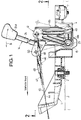
- a lever bracket 1 made of resin is mounted on a floor board of a motor vehicle through a mount rubber 2.
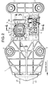
- the lever bracket 1 is integrally provided with first and second towers 3 and 4 which are juxtaposed in a lateral direction of the motor vehicle and which commonly includes a partition wall (Figs.2 and 4).
- the first tower 3 is substantially foursquare in section, and is opened at its lower surface.
- the second tower 4 is rectangular which is long in a longitudinal direction of the motor vehicle and opened at its upper and lower ends.
- the first tower 3 is integrally and continuously formed with a housing 5 which is suspended downward from an upper end wall 3a of the first tower 3 along an axis of the tower 3. Opposed peripheral surfaces of the housing 5 and the first tower 3 are connected by a plurality of radial reinforcing ribs 6.
- the housing 5 includes an upper large-diameter cylindrical portion 8 and a lower small-diameter cylindrical portion 9 which are juxtaposed so as to sandwich a step portion 7 provided at an intermediate portion of the housing 5.
- the small-diameter cylindrical portion 9 includes a hemispherical bottom wall 9a.
- the small-diameter cylindrical portion 9 is formed in an inner surface thereof with a guide groove 10 which extended vertically. (see Figs.2 and 4).
- a plurality of engagement holes 11 are formed in the large-diameter cylindrical portion 8 so as to face the step portion 7.
- vertically slotted holes 12 and 13 are formed in opposed side walls of the small-diameter cylindrical portion 9 and the second tower 4.
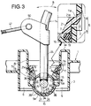
- a spherical fulcrum member 15 of the change lever 14 is rotatably engaged with the hemispherical bottom wall 9a of the small-diameter cylindrical portion 9.
- a cap 16 made of resin is relatively rotatably engaged with the fulcrum member 15 from above and is fitted to an inner peripheral surface of the small-diameter cylindrical portion 9.
- a rotation-proof projection 17 (Figs.2 and 5) projected from one side surface of the cap 16 is engaged with the guide groove 10.
- a surface 16a of the cap 16 which is in contact with an outer peripheral surface the fulcrum member 15 is formed into a spherical surface so as to fit such outer peripheral surface.
- the cap 16 is formed at its outer periphery of the upper end thereof with an annular recess 20 for holding an elastic ring 19 such as an O-ring.
- An annular retainer 21 (Fig.5) made of resin for compressing the elastic ring 19 from above so as to press and hold the cap 16 is fitted to inner peripheral surfaces of the large- and small-diameter cylindrical portions 8 and 9.
- a plurality of resilient (eg elastic ) engagement claws 22 projected from an outer pheriphery of the retainer 21 are engaged with the engagement holes 11.
- a tip end of the engagement claw 22 is inclined upward.
- the engagement claw 22 is deflected inward by an inner surface of the large-diameter cylindrical portion 8, and when the engagement claw 22 reaches a position corresponding to the engagement hole 11, the engagement claw 22 engages the engagement hole 11 by its own resilient force.
- the retainer 21 is provided with a step portion 21a which is opposed to the step portion 7 of the housing 5, so that when the retainer 21 is fitted to the housing 5, the compression deformation of the elastic ring 19 by abutment between both the step portions 7 and 21a can be restrained.
- the fulcrum member 15 is rotatably interposed between the cap 16 and the bottom wall 9a of the housing 5 and is subjected to a compressive force applied to the elastic ring 19.
- the change lever 14 includes a bar-like main lever 24 provided at its upper end with a knob 24a, and a bar-like subsidiary lever 25 welded to a lower end of the main lever 24 so as to form a T-shape.
- the subsidiary lever 25 includes long and short rod portions 25a and 25b.
- the long rod portion 25 largely projects from one side of the main lever 24 to pass through the slotted holes 12 and 13 and extends into the second tower 4.
- the short rod portion 25b slightly projects from the other side of the main lever 24.
- the fulcrum member 15 is secured to a junction between the main and the subsidiary levers 24 and 25 so as to cover the junction.
- the fulcrum member 15 is formed into a hollow structure by coupling a pair of cup-like hemispherical bodies 27 and 28 made of resin.
- the hemispherical bodies 27 and 28 have basically symmetrical shapes with respect to a mating surface therebetween.
- Each of the hemispherical bodies 27 and 28 is formed at an end surface thereof with supporting recesses 29, 30 and 31 extending three directions. These supporting recesses 29, 30 and 31 are fitted to outer peripheries of the main lever 24, as well as the long and short rod portions 25a and 25b of the subsidiary lever 25. At that time, centers of both the hemispherical bodies 27 and 28 are aligned with a junction of axes of the main and subsidiary levers 24 and 25.
- a plurality of positioning holes 33 are formed at the end surface of the hemispherical body 27, and a plurality of positioning projections 32 are formed at the end surface of the hemispherical body 28. By lightly fitting the positioning projections 32 into the positioning holes 33, both the hemispherical bodies 27 and 28 can temporarily be coupled.
- the coupling state between the hemispherical bodies 27 and 28 is reliably retained by sandwiching them between the cap 16 and the bottom wall 9a of the housing 5, as described above.
- Each of the hemispherical bodies 27 and 28 is filled with grease.
- the hemispherical bodies 27 and 28 are formed at their lower mating surfaces and other appropriate portions with grease holes 35 for exuding the grease to the outer periphery of the fulcrum member 15.
- the hemispherical bodies 27 and 28 are also formed at an outer periphery thereof with one or more annular grease recesses 36 to which many of the grease holes 35 are opened.
- the hemispherical bodies 27 and 28 are formed at outer peripheries of the end portions thereof with chamfers 34 which are formed during molding. Therefore, when the hemispherical bodies 27 and 28 are formed by a pair of metal dies 37 and 38 as shown in Fig.7, if juncture surfaces of both the metal dies 37 and 38 are brought together with the end surfaces of the hemispherical bodies 27 and 28, it is possible to prevent a burr which protrudes from the produced cavity such as to infiltrate into a clearance between the juncture surfaces of the metal dies 37 and 38, from projecting outward of the outer peripheries of the sperical surface of the hemispherical bodies 27 and 28. Therefore, even if the hemispherical bodies 27 and 28 are assembled into the housing 5 with a burr left as it is, it is possible to prevent the burr from damaging mating members.
- a bell-crank 41 made of resin is mounted to the second tower 4 through a horizontal pivot shaft 40.
- the bell-crank 41 includes a horizontal arm 41a having a swinging end extended forward, and a vertical arm 41b having a swinging end extended upward.
- a bush 43 rotatably mounted to a tip end of the subsidiary lever 25 is slidably fitted to a connection hole 41 formed in the inner surface of the horizontal arm 41a.
- One end of a push-pull select wire 44 is connected to the vertical arm 41b through a rod 46 having a turn buckle 48.
- one end of a push-pull shift wire 45 is connected to a connection piece 50 connected to an intermediate portion of the main lever 24 through a rod 47 having a turnbuckle 49.
- the other ends of the select wire 44 and the shift wire 45 are respectively connected to a select member and a shift member of a transmission (not shown).
- the vertically swingable subsidiary lever 25 drives the horizontal arm 41a of the bell-crank 41 so as to swing the vertical arm 41b in a longitudinal direction of the motor vehicle. Therefore, a select motion is applied to the transmission through the select wire 44, and a desired gear train is selected. Then, if the operator turns the main lever 24 about the fulcrum member 15 in a shift direction B (in a longitudinal direction of the vehicle), a shift motion is applied to the transmission through the shift wire 45, thereby establishing the previously selected gear train.
- the pair of hemispherical bodies 27 and 28 forming the fulcrum member 15 are formed with three supporting recesses 29, 30 and 31 in which the main and subsidiary levers 24 and 25 intersect each other to form a T-shape. Therefore, it is possible to easily and reliably prevent a relative displacement between the change lever 14 and the fulcrum member 15 in the axial and rotational directions. Therefore, when the change lever 14 is operated, a rotational sliding movement between each contacting surface of the housing 5, the cap 16 and the fulcrum member 15 which is lubricated with the grease is smoothly generated.
- Grease which is exuded from the fulcrum member 15 through the grease holes 35 is supplied to the contacting surfaces, so that excellent lubrication is always maintained. Furthermore, since most of the grease holes 35 are opened to the grease recess 36, grease exuded from the hoses 35 is retained in the recess 36 and thus excellent lubrication can be maintained for a long time. Also, the grease holes 35 provided in mating surfaces of the hemispherical bodies 27 and 28 are opened to the chamfers 34 formed at the outer peripheries of the end portions of the hemispherical bodies 27 and 28. Therefore, the chamfers 34 can also retain the exuded grease in the same manner as the grease recess 36. Therefore, the chamfers 34 also correspond to the grease recess of the present invention.
- the cap 16 and the bottom wall 9a of the housing 5 cooperatively sandwich the fulcrum member 15 with a compressive force, so that frictional wear generated therebetween can automatically be compensated for to prevent backlash from being generated. Further, when the elastic ring 19 permits an engagement between the engage claw 22 and the engage hole 11 and holds such engagement state without generating a backlash. Therefore, an attachment member for the retainer 21 becomes unnecessary, which facilitates assembly and simplifies the structure.
- the tip end of the engage claw 22 of the retainer 21 is inclined upward, and the upper surface 11a of the engage hole 11 of the housing 5 is also inclined upward in a radially outward direction. Therefore, if the retainer 21 receives an upward load from the side of the cap 16, the engagement claw 22 further strengthens the engagement with the engage hole 11, which reliably prevents the retainer 21 from being disengaged from the housing 5.
- Fig.8 shows a second embodiment in which, the subsidiary lever 25 intersects one side surface of the main lever 24 so as to form a T-shape.
- the hemispherical bodies 27 and 28 are provided at outer peripheral surfaces thereof with a large number of dimples 51 as grease recesses, and each of the hemispherical bodes 27 and 28 is also provided with a grease hole 52 which is opened at a bottom surface of each dimple 51.
- Other structures of the second embodiment are the same as those of the above-described first embodiment.
- portions or components corresponding to those in the first embodiment are designated by like reference characters.
- lubrication around the fulcrum member 15 can be conducted more effectively.
- the hemispherical bodies 27 and 28 may be formed of press steel plate or die cast aluminium.
Landscapes
- Engineering & Computer Science (AREA)
- General Engineering & Computer Science (AREA)
- Mechanical Engineering (AREA)
- Arrangement Or Mounting Of Control Devices For Change-Speed Gearing (AREA)
Applications Claiming Priority (6)
| Application Number | Priority Date | Filing Date | Title |
|---|---|---|---|
| JP32818994 | 1994-12-28 | ||
| JP32818994A JP3214793B2 (ja) | 1994-12-28 | 1994-12-28 | チェンジレバーの支持構造 |
| JP328189/94 | 1994-12-28 | ||
| JP1369/95 | 1995-01-09 | ||
| JP136995 | 1995-01-09 | ||
| JP136995A JPH08189558A (ja) | 1995-01-09 | 1995-01-09 | チェンジ装置の潤滑構造 |
Publications (3)
| Publication Number | Publication Date |
|---|---|
| EP0719965A2 true EP0719965A2 (de) | 1996-07-03 |
| EP0719965A3 EP0719965A3 (de) | 1997-06-04 |
| EP0719965B1 EP0719965B1 (de) | 2000-03-08 |
Family
ID=26334577
Family Applications (1)
| Application Number | Title | Priority Date | Filing Date |
|---|---|---|---|
| EP95303803A Expired - Lifetime EP0719965B1 (de) | 1994-12-28 | 1995-06-05 | Lagerelement für Schalthebel |
Country Status (3)
| Country | Link |
|---|---|
| US (1) | US5626057A (de) |
| EP (1) | EP0719965B1 (de) |
| DE (1) | DE69515449T2 (de) |
Cited By (1)
| Publication number | Priority date | Publication date | Assignee | Title |
|---|---|---|---|---|
| ITTO20111083A1 (it) * | 2011-11-24 | 2013-05-25 | Sila Holding Industriale Spa | Leva di comando con sfera di snodo integrata, particolarmente per i l comando del cambio di velocita' di un autoveicolo. |
Families Citing this family (14)
| Publication number | Priority date | Publication date | Assignee | Title |
|---|---|---|---|---|
| KR970061598A (ko) * | 1996-02-29 | 1997-09-12 | 야마베 미찌히꼬 | 자동차용 수동 변속기의 조작 레버 장치 |
| US6338589B1 (en) | 1998-07-14 | 2002-01-15 | American Axle & Manufacturing, Inc. | Hybrid ball stud |
| US20030140723A1 (en) * | 2002-01-29 | 2003-07-31 | Teleflex Automotive Germany Gmbh | Bearing sphere for a gear shift lever |
| US20030213326A1 (en) * | 2002-05-14 | 2003-11-20 | Fett Brian W. | Cable-operated transmission shifters |
| US7940673B2 (en) | 2007-06-06 | 2011-05-10 | Veedims, Llc | System for integrating a plurality of modules using a power/data backbone network |
| US8303337B2 (en) | 2007-06-06 | 2012-11-06 | Veedims, Llc | Hybrid cable for conveying data and power |
| US20090223318A1 (en) * | 2008-03-06 | 2009-09-10 | Ballard Claudio R | Gear shift assembly |
| US7856158B2 (en) | 2008-03-07 | 2010-12-21 | Ballard Claudio R | Virtual electronic switch system |
| US8667648B2 (en) * | 2011-08-26 | 2014-03-11 | Mtd Products Inc | Ball handle assembly for a handheld tool |
| US8976541B2 (en) | 2011-08-31 | 2015-03-10 | Potens Ip Holdings Llc | Electrical power and data distribution apparatus |
| CN102364167A (zh) * | 2011-10-26 | 2012-02-29 | 奇瑞汽车股份有限公司 | 一种汽车手动换档操纵机构 |
| WO2017005288A1 (en) * | 2015-07-06 | 2017-01-12 | Kongsberg Automotive Ab | Gearshift assembly |
| KR101806711B1 (ko) * | 2016-06-15 | 2017-12-07 | 현대자동차주식회사 | 수동변속기의 변속레버 어셈블리 |
| US10881362B2 (en) * | 2018-11-20 | 2021-01-05 | General Electric Company | Systems for laser alignment |
Citations (1)
| Publication number | Priority date | Publication date | Assignee | Title |
|---|---|---|---|---|
| JPH05240329A (ja) | 1992-02-14 | 1993-09-17 | Bba Group Plc | シフトレバー構造 |
Family Cites Families (6)
| Publication number | Priority date | Publication date | Assignee | Title |
|---|---|---|---|---|
| US2638850A (en) * | 1952-01-24 | 1953-05-19 | Ferris Walter | Piston assembly for axial type hydrodynamic machines |
| US4662772A (en) * | 1985-11-08 | 1987-05-05 | Dana Corporation | Shift lever tower assembly |
| US4693135A (en) * | 1986-06-05 | 1987-09-15 | Wickes Manufacturing Company | Manually operable gearshift mechanism |
| US4986688A (en) * | 1990-04-16 | 1991-01-22 | Tuan C T | Structure of ball and socket joint for a vehicle steering control system |
| GB2248659B (en) * | 1990-09-07 | 1994-10-12 | Railko Limited | A gear lever structure |
| US5265495A (en) * | 1992-09-21 | 1993-11-30 | Teleflex Incorporated | Isolated shifter terminal assembly |
-
1995
- 1995-06-01 US US08/456,377 patent/US5626057A/en not_active Expired - Fee Related
- 1995-06-05 DE DE69515449T patent/DE69515449T2/de not_active Expired - Fee Related
- 1995-06-05 EP EP95303803A patent/EP0719965B1/de not_active Expired - Lifetime
Patent Citations (1)
| Publication number | Priority date | Publication date | Assignee | Title |
|---|---|---|---|---|
| JPH05240329A (ja) | 1992-02-14 | 1993-09-17 | Bba Group Plc | シフトレバー構造 |
Cited By (1)
| Publication number | Priority date | Publication date | Assignee | Title |
|---|---|---|---|---|
| ITTO20111083A1 (it) * | 2011-11-24 | 2013-05-25 | Sila Holding Industriale Spa | Leva di comando con sfera di snodo integrata, particolarmente per i l comando del cambio di velocita' di un autoveicolo. |
Also Published As
| Publication number | Publication date |
|---|---|
| EP0719965A3 (de) | 1997-06-04 |
| US5626057A (en) | 1997-05-06 |
| DE69515449T2 (de) | 2000-11-23 |
| DE69515449D1 (de) | 2000-04-13 |
| EP0719965B1 (de) | 2000-03-08 |
Similar Documents
| Publication | Publication Date | Title |
|---|---|---|
| EP0719965B1 (de) | Lagerelement für Schalthebel | |
| US5653547A (en) | Spherical joint with an elastic cap | |
| US5092017A (en) | Automotive door hinge assembly, bush employed therein and method for installing bush in door hinge assembly | |
| US5497673A (en) | Automatic transmission operating device | |
| US2964341A (en) | Pivotal joint | |
| US4795288A (en) | Yoke member connecting device in windshield wiper | |
| JPH0712621U (ja) | ボールジョイント | |
| US6237435B1 (en) | Control device | |
| KR19990071745A (ko) | 보조부를 갖춘 전동 체인의 체인 링크 | |
| JPH0569009B2 (de) | ||
| JPH07259842A (ja) | ボール接手 | |
| US5560252A (en) | Change lever supporting structure | |
| US5896778A (en) | Operating lever device for manual transmissions for motor vehicles | |
| EP0978669A2 (de) | Schalthebel mit Handschalt- und Automatikmodus für Automatikgetriebe | |
| US5722296A (en) | Change device for transmission | |
| CN104179959A (zh) | 一种汽车自动换挡器 | |
| US7159486B2 (en) | Joint arrangement for a gear shift mechanism | |
| CZ104396A3 (en) | Process for producing ball-and-socket joint and apparatus for making the same | |
| JPH08189558A (ja) | チェンジ装置の潤滑構造 | |
| JPH0863250A (ja) | 連動機構 | |
| JP3214793B2 (ja) | チェンジレバーの支持構造 | |
| JP4105268B2 (ja) | 操作レバーの支点構造 | |
| US2257346A (en) | Power transmitting unit | |
| US4794812A (en) | Gear-shift lever having variable thickness walls | |
| CN217842622U (zh) | 一种换挡操纵器 |
Legal Events
| Date | Code | Title | Description |
|---|---|---|---|
| PUAI | Public reference made under article 153(3) epc to a published international application that has entered the european phase |
Free format text: ORIGINAL CODE: 0009012 |
|
| AK | Designated contracting states |
Kind code of ref document: A2 Designated state(s): DE FR GB IT |
|
| PUAL | Search report despatched |
Free format text: ORIGINAL CODE: 0009013 |
|
| AK | Designated contracting states |
Kind code of ref document: A3 Designated state(s): DE FR GB IT |
|
| 17P | Request for examination filed |
Effective date: 19970725 |
|
| 17Q | First examination report despatched |
Effective date: 19981117 |
|
| GRAG | Despatch of communication of intention to grant |
Free format text: ORIGINAL CODE: EPIDOS AGRA |
|
| RIC1 | Information provided on ipc code assigned before grant |
Free format text: 6F 16H 59/04 A, 6F 16H 61/36 B |
|
| RIC1 | Information provided on ipc code assigned before grant |
Free format text: 6F 16H 59/04 A, 6F 16H 61/36 B |
|
| GRAG | Despatch of communication of intention to grant |
Free format text: ORIGINAL CODE: EPIDOS AGRA |
|
| GRAH | Despatch of communication of intention to grant a patent |
Free format text: ORIGINAL CODE: EPIDOS IGRA |
|
| GRAH | Despatch of communication of intention to grant a patent |
Free format text: ORIGINAL CODE: EPIDOS IGRA |
|
| GRAA | (expected) grant |
Free format text: ORIGINAL CODE: 0009210 |
|
| AK | Designated contracting states |
Kind code of ref document: B1 Designated state(s): DE FR GB IT |
|
| PG25 | Lapsed in a contracting state [announced via postgrant information from national office to epo] |
Ref country code: IT Free format text: LAPSE BECAUSE OF FAILURE TO SUBMIT A TRANSLATION OF THE DESCRIPTION OR TO PAY THE FEE WITHIN THE PRE;WARNING: LAPSES OF ITALIAN PATENTS WITH EFFECTIVE DATE BEFORE 2007 MAY HAVE OCCURRED AT ANY TIME BEFORE 2007. THE CORRECT EFFECTIVE DATE MAY BE DIFFERENT FROM THE ONE RECORDED.SCRIBED TIME-LIMIT Effective date: 20000308 Ref country code: FR Free format text: LAPSE BECAUSE OF FAILURE TO SUBMIT A TRANSLATION OF THE DESCRIPTION OR TO PAY THE FEE WITHIN THE PRESCRIBED TIME-LIMIT Effective date: 20000308 |
|
| REF | Corresponds to: |
Ref document number: 69515449 Country of ref document: DE Date of ref document: 20000413 |
|
| EN | Fr: translation not filed | ||
| PLBE | No opposition filed within time limit |
Free format text: ORIGINAL CODE: 0009261 |
|
| STAA | Information on the status of an ep patent application or granted ep patent |
Free format text: STATUS: NO OPPOSITION FILED WITHIN TIME LIMIT |
|
| 26N | No opposition filed | ||
| REG | Reference to a national code |
Ref country code: GB Ref legal event code: IF02 |
|
| PGFP | Annual fee paid to national office [announced via postgrant information from national office to epo] |
Ref country code: DE Payment date: 20080415 Year of fee payment: 14 |
|
| PGFP | Annual fee paid to national office [announced via postgrant information from national office to epo] |
Ref country code: GB Payment date: 20080627 Year of fee payment: 14 |
|
| GBPC | Gb: european patent ceased through non-payment of renewal fee |
Effective date: 20090605 |
|
| PG25 | Lapsed in a contracting state [announced via postgrant information from national office to epo] |
Ref country code: GB Free format text: LAPSE BECAUSE OF NON-PAYMENT OF DUE FEES Effective date: 20090605 |
|
| PG25 | Lapsed in a contracting state [announced via postgrant information from national office to epo] |
Ref country code: DE Free format text: LAPSE BECAUSE OF NON-PAYMENT OF DUE FEES Effective date: 20100101 |