EP0720104A2 - Vorrichtung zur inversen, diskreten Cosinus-Transformation - Google Patents
Vorrichtung zur inversen, diskreten Cosinus-Transformation Download PDFInfo
- Publication number
- EP0720104A2 EP0720104A2 EP95119072A EP95119072A EP0720104A2 EP 0720104 A2 EP0720104 A2 EP 0720104A2 EP 95119072 A EP95119072 A EP 95119072A EP 95119072 A EP95119072 A EP 95119072A EP 0720104 A2 EP0720104 A2 EP 0720104A2
- Authority
- EP
- European Patent Office
- Prior art keywords
- discrete cosine
- cosine transform
- matrixes
- inverse discrete
- matrix
- Prior art date
- Legal status (The legal status is an assumption and is not a legal conclusion. Google has not performed a legal analysis and makes no representation as to the accuracy of the status listed.)
- Granted
Links
Images


Classifications
-
- G—PHYSICS
- G06—COMPUTING OR CALCULATING; COUNTING
- G06F—ELECTRIC DIGITAL DATA PROCESSING
- G06F17/00—Digital computing or data processing equipment or methods, specially adapted for specific functions
- G06F17/10—Complex mathematical operations
- G06F17/14—Fourier, Walsh or analogous domain transformations, e.g. Laplace, Hilbert, Karhunen-Loeve, transforms
- G06F17/147—Discrete orthonormal transforms, e.g. discrete cosine transform, discrete sine transform, and variations therefrom, e.g. modified discrete cosine transform, integer transforms approximating the discrete cosine transform
Definitions
- the present invention relates generally to a decoding apparatus for decoding data of a video signal compressed by discrete cosine transform in a communication system and a stored media system such as a video disk and a video tape, and more particularly to an inverse discrete cosine transform apparatus which is used for a band width compression processing system of the video signal.
- a circuit can be configured by an LSI by using a fast algorithm to reduce amount of computation.
- An example of the fast algorithm is disclosed in the prior art of a paper of "Fast Algorithms for the Discrete Cosine Transform", written by Ephraim Feig and Shmuel Winograd, IEEE Transaction on Signal Processing, September 1992. According to the paper, the amount of computation is reduced by decreasing frequencies of addition and subtraction, multiplication or the like. As to the order of the computations in the fast algorithm, the addition and subtraction is carried out after the multiplication.
- All multipliers in the multiplications are coefficients of cosine, therefore an error is produced by the multiplication.
- the error produced by the multiplication is accumulated in a subsequent addition and subtraction as an error of computation result.
- the number of bits for the coefficient of cosine must be increased, and the number of bits of resultant data of the computation must be also increased. Consequently, there is a problem that a scale of circuit inevitably increases when the computation is carried out by a hardware.
- the present invention is to solve the above-mentioned problems in the prior art.
- An object of the present invention is to provide an inverse discrete cosine transform apparatus which is capable of decreasing the number of bits after operations of basic operation matrixes and keeping a desired accuracy in a final output signal.
- Another object of the present invention is to provide an inverse discrete cosine transform apparatus including a two-dimensional inverse discrete cosine transform apparatus for attaining the above-mentioned object and decreasing the number of operating units by improving a low-column transposition method.
- the inverse discrete cosine transform apparatus is configured by combining plural operating units for basic operation matrixes such as rearrangement matrix, addition and subtraction matrix and multiplication matrix, such that the operations of addition and subtraction matrix are carried out prior to operation of the multiplication matrix at all times. Consequently, a frequency of the addition and subtraction after the multiplication can be reduced, and accumulation of an error after the addition and subtraction decreases.
- FIG.1 A first embodiment of the present invention is described with reference to FIG.1, FIG.2 and FIG.3.
- inverse DCT inverse discrete cosine transform
- a first kind through a fourth kind there are four kinds of inverse discrete cosine transform (hereinafter is referred to as inverse DCT), namely a first kind through a fourth kind.
- the present invention relates to the inverse DCT of the second kind.
- a coefficient of an eight inputs inverse DCT in the first embodiment is represented by equation (1).
- Equation (2) representing a fast algorithm of the prior art is derived by expanding the equation (1).
- a third matrix M 13 , a fourth matrix M 14 , a fifth matrix M 15 and a sixth matrix M 16 are operated, and equation (3) is derived.
- Equation (5) is derived by combining three matrixes G 1 , G 2 and G 3 in equation (4) and replacing with the matrixes M 13 , M 14 , M 15 and M 16 from the third to the sixth in equation (2).
- equation (5) is substantially identical with equation (6) cited in Claim 1.
- a matrix M 21 in equation (5) is identical with a matrix M 11 in equation (2), in a similar manner, a matrix M 22 is identical with a matrix M 12 , a matrix M 25 is identical with the matrix M 14 and a matrix M 27 is identical with a matrix M 17 .
- the inverse discrete cosine transform apparatus of the first embodiment is configured so as to operate the matrixes on the basis of equation (5). Consequently, the number of operations of the addition and subtraction matrixes which are carried out prior to operations of the multiplication matrixes increases. "Prior to” does not mean a location of a matrix in equation, but means an order of operation or processing in a time sequence. For example in equation (5), addition and subtraction matrixes M 26 and M 27 are operated prior to operation of the multiplication matrix M 25 . Moreover, an addition and subtraction matrix M 24 is operated prior to operation of a multiplication matrix M 23 .
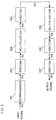
- FIG.1 is a diagram representing signal processing of the inverse discrete cosine transform apparatus corresponding to equation (5).
- a sign "+” represents addition by an adder.
- a numeral “-1” represents inversion of a sign by a sign inverter (not shown).
- C 1 , C 2 , C 3 , C 4 , C 5 , C 6 and C 7 represent multipliers in multiplication.
- the inverse discrete cosine transform apparatus produces a first output signal y 0 , a second output signal y 1 , a third output signal y 2 , a fourth output signal y 3 , a fifth output signal y 4 , a sixth output signal y 5 , a seventh output signal y 6 and eighth output signal y 7 from a first input signal x 0 , a second input signal x 1 , a third input signal x 2 , a fourth input signal x 3 , a fifth input signal x 4 , a sixth input signal x 5 , a seventh input signal x 6 and an eighth input signal x 7 .
- the input signals x 0 ---x 7 are transmitted rightward along respective lines and a plus sign or a minus sign of each input signal is inverted on a line having a representation of the numeral "-1". An addition of input signals is made at a position having the sign +.
- the input signal is multiplied by one of multipliers C 1 ---C 7 on a line having the said multiplier.
- the output signals y 0 ---y 7 are produced.
- a two-dimensional inverse discrete cosine transform apparatus which is used for the inverse discrete cosine transform apparatus of the present invention is described hereafter.
- a second basic operation matrix of 64 rows and 64 columns is derived by operating tensor product of the first basic operation matrixes in equation (5). Matrix operation of the second basic operation matrix of 64 rows and 64 columns and an input signal transposed from a matrix of 8 rows and 8 columns to a matrix of 64 rows and 1 column is carried out. Consequently, a signal of a matrix of 64 rows and 1 column is obtained.
- the two-dimensional inverse discrete cosine transform apparatus can be configured so as to produce a two-dimensional output signal which is transposed from the matrix of 64 rows and 1 column to a matrix of 8 rows and 8 columns.
- the two-dimensional inverse discrete cosine transform apparatus is configured so as to meet an accuracy of operation of the inverse DCT part of H.261 standard in the CCITT recommendation.
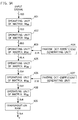
- FIG.2 is a flow chart of a process of the above-mentioned two-dimensional inverse discrete cosine transform apparatus.
- integral parts represent the number (m) of bits of integral data
- decimal parts represent the number (n) of bits of decimal data (m, n:integers).
- additions are carried out prior to each multiplication at all times.
- an addition 202 is carried out prior to a multiplication 203.
- an addition 204 is carried out prior to a multiplication 205. Consequently, only two additions 206 and 207 are carried out after the multiplication 205.
- the number of addition operations after multiplication operations is reduced in comparison with the paper of the prior art cited in the "description of the prior art".
- three additions are carried out after a multiplication as represented by equations 77, 78, 79 and 80 of page 2184 of the paper.
- the operation of the matrix M 27 is equivalent to a rearrangement 201
- the operation of the matrix M 26 is equivalent to the addition 202
- the operation of the matrix M 25 is equivalent to the multiplication 203
- the operation of the matrix M 24 is equivalent to the addition 204.
- the operation of the matrix M 23 is equivalent to the multiplication 205 and the operation of the matrix M 22 is equivalent to the addition 206.
- the operation of the matrix M 21 is equivalent to the addition 207.
- Required numbers of bits of the data of the input signal and the output signal after the respective matrix operations are as follows: the data of the input signal ⁇ 12.0 bits, the data after operation of the seventh matrix M 27 ⁇ 12.0 bits, the data after operation of the sixth matrix M 26 ⁇ 13.0 bits, the data after operation of the fifth matrix M 25 ⁇ 14.6 bits, the data after operation of the fourth matrix M 24 ⁇ 14.4 bits, the data after operation of the third matrix M 23 ⁇ 10.6 bits, the data after operation of the second matrix M 22 ⁇ 10.6 bits, and the data after operation of the first matrix M 21 ⁇ 9.0 bits.
- a total number of bits of integral parts is 94, and a total number of bits of decimal parts is 22.
- the number of bits is 116 in total. Since in the prior art Feig et al., the total number of bits necessary for meeting the H.261 standard is estimated 130, a circuit scale of the inverse discrete cosine transform apparatus of the first embodiment is smaller than that of the prior art. Memory circuits such as a latch and a RAM for storing data after operations can be reduced by decreasing the total number of bits, and therefore an area occupied by such memory circuits is also decreased. Moreover, the numbers of bits which are required in operation of the adders and multipliers are also reduced. Assessment result in the case of the first embodiment is shown in table (1).
- the table (1) represents an assessment based on "The inverse transform accuracy specification of H.261 standard”.
- TABLE 1 Range of random members Peak mean square error for any of 64 IDCT Overall mean square error of 64 IDCT output pels Peak mean error for any of 64 IDCT output pels mean error of 64 IDCT output pels -256 ⁇ 255 0.029800 0.016978 0.011200 0.000066 -5 ⁇ 5 0.024000 0.011311 0.008600 0.000145 -300 ⁇ 300 0.027000 0.015695 0.009000 0.000114 H.261 standard values 0.06 and below 0.02 and below 0.015 and below 0.0015 and below
- FIG.3A and FIG.3B in combination show a detailed block diagram of the two-dimensional inverse discrete cosine transform apparatus for carrying out the operations in FIG.2.
- the numeral values 12.0 and 13.0 represent the numbers of bits of data as mentioned above.
- data of an input signal 301 are latched by a demultiplexer 302, and are distributed to built-in memories (not shown) and held thereby.
- Data to be operated are selected by a multiplexer 303, and added by an adder 304.
- the adder 304 the rearrangement 201 and the addition 202 in FIG.2 are carried out.
- Output data of 13.0 bits after addition of the adder 304 are distributed to a multiplexer 307 and an adder 306 by a demultiplexer 305.
- Output data of the adder 306 are applied to the multiplexer 307.
- Output data of the multiplexer 307 are applied to a multiplier 309, and multiplied by data of 2.17 bits of an inverse DCT coefficient generating unit 308.
- the output data of the multiplier 309 are applied to a demultiplexer 310, and thereby distributed to an adder 311 and a multiplexer 312.
- the output data of the adder 311 are applied to the multiplexer 312, and output data of 14.6 bits are obtained every one clock signal.
- Input data are latched by respective demultiplexers 313, 318 and 321 and distributed to respective memories (not shown), and thereby the input data are held. Selections of data to be operated are carried out by multiplexers 314, 319 and 322. Additions are carried out by adders 315, 320 and 323. As to multiplication 205 in FIG.2, in FIG.3B, data of 2.12 bits of an inverse DCT coefficient generating unit 316 are multiplied by an input data of 14.4 bits from the adder 315 in a multiplier 317 in a predetermined order. After completion of all operations, one output signal 324 is obtained every one clock signal.
- the operation of the addition and subtraction matrix is carried out prior to operation of each multiplication matrix at all times. Therefore, the number of operation of the addition and subtraction matrix which are carried out after the operation of the multiplication matrix can be reduced.
- the number of bits of data after operations of the matrixes can be reduced by keeping a desired accuracy. Consequently, in configuration of a hardware, a circuit scale can be reduced.
- FIG.4 A second embodiment in accordance with the present invention is described with reference to FIG.4, FIG.5, FIG.6, FIG.7, FIG.8 and FIG.9.
- a row-column transposition method is applied to a part of plural matrixes such as addition and subtraction matrixes.
- Tensor product operation is applied to other matrixes in the two-dimensional inverse discrete cosine transform apparatus.
- A, B, C, D four basic operation matrixes of 8 rows and 8 columns are represented by A, B, C, D.
- Y DCBA *X*A T B T C T D T
- transposed matrixes of the basic operation matrixes A, B, C, D are represented by A T , B T , C T , D T , respectively.
- the tensor product operation is applied to the basic operation matrix C, and the basic operation matrixes A, B, D are operated by the row-column transposition method.
- the two-dimensional inverse discrete cosine transform apparatus is configured as shown in FIG.4.
- a tensor product C' in an operating unit 356 is a matrix of 64 rows and 64 columns.
- a matrix of 64 rows and 1 column is inputted to the operating unit 356, and a matrix of 8 rows and 8 columns is output therefrom. Operations of the basic operation matrixes A, B, D are carried out with respect to an input of 8 rows and 8 columns.
- an output of 8 rows and 8 columns is obtained by performing operations of eight times with respect to eight inputs in the row direction or column direction.
- the tensor product operation is carried out in a manner that an input of 8 rows and 8 columns is transposed to an input of 64 rows and 1 column.
- a resultant output is transposed from the output of 64 rows and 1 column to the output of 8 rows and 8 columns.
- a holding device such as a latch or a memory is unnecessary.
- Equation (8) is derived by deforming equation (6).
- equation (8) multiplication matrixes become diagonal matrixes which do not include addition and subtraction operation. Consequently, tensor product operation is simplified, and the multiplication matrixes become diagonal matrixes after the tensor product operation.
- the holding device such as the latch or memory is unnecessary when compared with the first embodiment of equations (5) and (6). Therefore, the circuit scale can be reduced. Derivation of equation (8) is described hereafter.
- Matrixes as shown by equation (9) are derived by operations of the matrixes M 12 , M 13 , M 14 , M 15 and M 16 in equation (2).
- Two matrixes L 1 and L 2 of 4 rows and 4 columns in equation (9) are deformed to matrixes L 1 and L 2 as shown by equation (10), respectively.
- Two matrixes L 1 and L 2 in equation (10) are combined, and are substituted for the matrixes M 12 --- M 16 from the second to the sixth of equation (2). Consequently, equation (2) is represented by equation (11).
- multiplication matrixes M 32 , M 33 , M 35 and M 37 are diagonal matrixes.
- the multiplication matrixes M 32 and M 33 can be combined to one orthogonal matrix, for convenience of description, the multiplication matrixes M 32 and M 33 are represented by separate orthogonal matrixes.
- respective addition and subtraction matrixes are operated prior to operation of each multiplication matrix at all times.
- the addition and subtraction matrix M 34 is operated prior to operation of the multiplication matrixes M 32 and M 33 .
- the addition and subtraction matrix M 36 is operated prior to operation of the multiplication matrix M 35 .
- the addition and subtraction matrix M 38 is operated prior to operation of the multiplication matrix M 37 .
- FIG.6 is a diagram representing signal processing of the inverse discrete cosine transform apparatus corresponding to equation (11).
- a sign "+” represents addition by an adder.
- a numeral “-1” represents inversion of a sign by a sign inverter (not shown).
- C 1 , C 2 , C 3 , C 4 , C 5 , C 6 and C 7 represent multipliers in multiplication.
- the inverse discrete cosine transform apparatus produces a first output signal y 0 , a second output signal y 1 , a third output signal y 2 , a fourth output signal y 3 , a fifth output signal y 4 , a sixth output signal y 5 , a seventh output signal y 6 and eighth output signal y 7 from a first input signal x 0 , a second input signal x 1 , a third input signal x 2 , a fourth input signal x 3 , a fifth input signal x 4 , a sixth input signal x 5 , a seventh input signal x 6 and an eighth input signal x 7 .
- Operations in columns which are sectioned by dotted lines and indicated by M 31 ---M 39 correspond with the operations of the basic operation matrixes M 31 ---M 39 in equation (11), respectively.
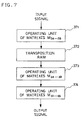
- FIG.7 is a block diagram of a two-dimensional inverse discrete cosine transform apparatus for carrying out the above-mentioned operation.
- an operating unit 371 of matrixes M 34 ---M 39 which operates on the basis of the row-column transposition method carries out operations in the columns of M 34 ---M 39 in FIG. 6.
- An operating unit 374 of the matrixes M 31 ---M 33 which operates on the basis of two-dimensional matrixes derived by tensor product operation carries out operations in the columns of M 31 ---M 33 in FIG.6.
- the matrixes M 31 ---M 33 in equation (11) a hardware for operating two-dimensional matrixes derived by tensor product operation is described hereafter.
- the tensor product of the matrix M 33 is a diagonal matrix of 64 rows and 64 columns, and the elements on the diagonal are multiplied by 1/2.
- a multiplier is not needed because the operation can be carried out by shifting one bit.
- the multiplication can be carried out at an arbitrary operation step.
- the matrix M 32 becomes a diagonal matrix of 64 rows and 64 columns by tensor product operation.
- a hardware for realizing the operation can be configured by one multiplier because the inputs of 64 rows and 1 column can be multiplied every input of a clock signal in sequence.
- the matrix M 31 becomes a matrix of 64 rows and 64 columns by tensor product operation.
- a hardware for carrying out the tensor product operation requires two addition-and-subtraction units 392 and 394, and further, two holding apparatus 391 and 393 such as a latch and a RAM.
- a hardware which carries out operation based on the row and column transposition method of one-dimensional matrix is described hereafter.
- data are inputted in synchronism with a clock signal, eight inputs of one unit in the direction of a row or a column are inputted by input of 8 clock signals.
- a part of one-dimensional operation forms pipelines for carrying out parallel operations of eight steps. That is, when the addition and the multiplication are carried out in synchronism with the clock signal, one adder and one multiplier are capable of operating eight times.
- the number of multiplications is 7 in total.
- Three multiplications by the coefficient 2C 4 which are equivalent to operation of the matrix M 37 are carried out by input of 8 clock signals in one-dimensional operation. Therefore, in the two-dimensional operation, six multiplications of twice of three are carried out. Since the number of pipelines for carrying out parallel operations is eight, six multiplications by input of 8 clock signals can be carried out by using one multiplier.
- the multiplier can be configured by a small scale circuit using only an adder and a shift circuit.
- the multiplier can be configured by a small scale circuit using a multiplexer, an adder and a shift circuit.
- twenty-nine additions and thirteen multiplications are carried out in the one-dimensional inverse discrete cosine transform. Therefore, in order to perform these operations by input of 8 clock signals, four adders and two multipliers must be used. Consequently, in order to configure apparatus for two-dimensional inverse discrete cosine transform using the row-column transposition method, eight adders and four multipliers are required because two units of the one-dimensional inverse discrete cosine transform apparatus are required.
- operating units of the matrixes M 34 and M 36 can be configured by a selector, an addition-and-subtraction unit for outputting an operation result of addition or subtraction of two inputs, a multiplexer, and a latch for holding the operation result.
- An operation unit of the matrix M 38 can be configured by a selector, one adder and a latch for holding an operation result.
- FIG.9A and FIG.9B in combination show a block diagram of the two-dimensional inverse discrete cosine transform apparatus of the second embodiment.
- the number of bits which is required to operation of each basic operation matrix is indicated by a numeral value 12.0, for example.
- numeral value 12.0 for example, the integral part represents the number (m) of bits of data of integer, and the decimal part represents the number (n) of bits of data of decimal (m and n are integers).
- the integers m and n represent the numbers of bits which are required for output data after operation of each basic operation matrix.
- the numbers of bits of inverse DCT coefficients are indicated under respective arrows representing outputs of inverse DCT coefficient generating units 404, 407, 413, 416 and 419.
- the indicated number of bits is required in the case that an operating unit is not an exclusive multiplier which is configured by an adder and a shift circuit, but a conventional multiplier.
- the matrixes M 31 , M 32 and M 33 having prime "'" represent tensor products of the respective matrixes. Referring to FIG.9A and 9B, the number of bits which is required to each operating unit is described hereafter.
- an operating unit 402 of the matrix M 38 requires 13 bits.
- an operating unit 420 of the matrix M 31 ' requires 36 bits twice of 18 bits, and a signal of 18 bits is inputted and a signal of 9 bits is output.
- the operating unit 415 comprises an adder, a shift circuit and a rounding circuit (these are not shown) so that the input data are multiplied by an inverse DCT coefficient of 2.12 bits output from the inverse DCT coefficient generating unit 416 and output data of 14.4 bits are obtained.
- the operating unit 412 also comprises an adder, a shift circuit and a rounding circuit (these are not shown) so that the input data are multiplied by an inverse DCT coefficient of 2.14 bits output from the inverse DCt coefficient generation unit 413 and output data of 14.4 bits are obtained.
- the operating unit 418 of matrixes (M 32 * M 33 )' of two-dimensional operation requires one multiplier so that input data of 15.4 bits are multiplied by an inverse DCT coefficient of 2.11 bits output from the inverse DCT coefficient generating unit 419 and output data of 11.7 bits are obtained.
- Assessment result of the second embodiment is shown in table 2 which is similar to table 1.
- Peak mean square error for any of IDCT output pels Overall mean square error of 64 IDCT output pels Peak mean error for any of 64 IDCT output pels mean error of 64 IDCT output pels -256 ⁇ 255 0.030300 0.015877 0.003200 0.000108 -5 ⁇ 5 0.027500 0.014764 0.003100 0.000011 -300 ⁇ 300 0.020700 0.009533 0.002800 0.000003 H.261 standard values 0.06 and below 0.02 and below 0.015 and below 0.0015 and below
- the number of multipliers can be reduced by combining the operation based on the row-column transposition method and the two-dimensional operation which applies the tensor product operation to a part of plural basic operation matrixes. Moreover, the number of bits of data after operations of the respective basic operation matrixes can be reduced keeping a desired operation accuracy. Consequently, a circuit scale of the inverse discrete cosine transform apparatus can be reduced.
- FIG.10 A third embodiment in accordance with the present invention is described with reference to FIG.10.
- a circuit which operates on the basis of the row-column transposition method is shown in FIG. 10.
- input data of 8 rows and 8 columns are transmitted to an operating unit 453 of one-dimensional matrix through a selector 452 and operated.
- Resultant output data are transmitted to a transposition RAM 456 through a multiplexer 454.
- the data of 8 rows and 8 columns are inputted to the transposition RAM 456, and the rows and the columns are interchanged in the output.
- the data output from the transposition RAM 456 are transmitted to the operating unit 453 of one-dimensional matrix through the selector 452, and again operated thereby.
- Resultant output data are transmitted to an operating unit 455 of tensor product for carrying out two-dimensional operation through the multiplexer 454 and operated thereby.
- the selector 452 for switching between the input data and the data output from the transposition RAM 456 is controlled by a timing control circuit 451.
- the multiplexer 454 for switching the output of the operating unit 453 of one-dimensional matrix between the operating unit 455 and the transposition RAM 456 is also controlled by the timing control circuit 451.
- the operation by the row-column transposition method is repeated twice by using one operating unit 453 of one-dimensional matrix, and thereby, the two-dimensional operation is attained. Therefore, a circuit scale of the operating unit 453 of one-dimensional matrix is reduced.
Landscapes
- Physics & Mathematics (AREA)
- Engineering & Computer Science (AREA)
- General Physics & Mathematics (AREA)
- Mathematical Physics (AREA)
- Mathematical Analysis (AREA)
- Data Mining & Analysis (AREA)
- Computational Mathematics (AREA)
- Pure & Applied Mathematics (AREA)
- Mathematical Optimization (AREA)
- Theoretical Computer Science (AREA)
- Discrete Mathematics (AREA)
- Databases & Information Systems (AREA)
- Software Systems (AREA)
- General Engineering & Computer Science (AREA)
- Algebra (AREA)
- Complex Calculations (AREA)
- Compression Or Coding Systems Of Tv Signals (AREA)
- Compression Of Band Width Or Redundancy In Fax (AREA)
Applications Claiming Priority (6)
| Application Number | Priority Date | Filing Date | Title |
|---|---|---|---|
| JP30187294 | 1994-12-06 | ||
| JP30187294 | 1994-12-06 | ||
| JP301872/94 | 1994-12-06 | ||
| JP27894795 | 1995-10-26 | ||
| JP278947/95 | 1995-10-26 | ||
| JP27894795A JPH08235159A (ja) | 1994-12-06 | 1995-10-26 | 逆コサイン変換装置 |
Publications (3)
| Publication Number | Publication Date |
|---|---|
| EP0720104A2 true EP0720104A2 (de) | 1996-07-03 |
| EP0720104A3 EP0720104A3 (de) | 1996-10-30 |
| EP0720104B1 EP0720104B1 (de) | 2002-08-28 |
Family
ID=26553111
Family Applications (1)
| Application Number | Title | Priority Date | Filing Date |
|---|---|---|---|
| EP95119072A Expired - Lifetime EP0720104B1 (de) | 1994-12-06 | 1995-12-04 | Verfahren zur inversen, diskreten Cosinus-Transformation |
Country Status (4)
| Country | Link |
|---|---|
| US (1) | US5724278A (de) |
| EP (1) | EP0720104B1 (de) |
| JP (1) | JPH08235159A (de) |
| DE (1) | DE69527930T2 (de) |
Cited By (1)
| Publication number | Priority date | Publication date | Assignee | Title |
|---|---|---|---|---|
| WO2003021966A1 (en) * | 2001-09-06 | 2003-03-13 | Oulun Yliopisto | Method and device for coding successive images |
Families Citing this family (27)
| Publication number | Priority date | Publication date | Assignee | Title |
|---|---|---|---|---|
| US6336180B1 (en) | 1997-04-30 | 2002-01-01 | Canon Kabushiki Kaisha | Method, apparatus and system for managing virtual memory with virtual-physical mapping |
| JPH1063646A (ja) * | 1996-08-23 | 1998-03-06 | Nec Corp | 2次元逆離散コサイン変換回路 |
| JP3092526B2 (ja) * | 1996-09-20 | 2000-09-25 | 日本電気株式会社 | 2次元逆離散コサイン変換回路 |
| US6003056A (en) * | 1997-01-06 | 1999-12-14 | Auslander; Lewis | Dimensionless fast fourier transform method and apparatus |
| AUPO648397A0 (en) | 1997-04-30 | 1997-05-22 | Canon Information Systems Research Australia Pty Ltd | Improvements in multiprocessor architecture operation |
| US6061749A (en) | 1997-04-30 | 2000-05-09 | Canon Kabushiki Kaisha | Transformation of a first dataword received from a FIFO into an input register and subsequent dataword from the FIFO into a normalized output dataword |
| US6504871B1 (en) * | 1997-07-31 | 2003-01-07 | Lsi Logic Corporation | IDCT processor for use in decoding MPEG compliant video bitstreams meeting 2-frame and letterboxing requirements |
| GB9722982D0 (en) * | 1997-10-31 | 1998-01-07 | Integrated Silicon Systems Lim | A commutator circuit |
| JPH11143860A (ja) * | 1997-11-07 | 1999-05-28 | Matsushita Electric Ind Co Ltd | 直交変換装置 |
| US6088019A (en) * | 1998-06-23 | 2000-07-11 | Immersion Corporation | Low cost force feedback device with actuator for non-primary axis |
| US6211861B1 (en) * | 1998-06-23 | 2001-04-03 | Immersion Corporation | Tactile mouse device |
| US6295320B1 (en) * | 1997-12-31 | 2001-09-25 | Lg Electronics Inc. | Inverse discrete cosine transforming system for digital television receiver |
| US6717573B1 (en) | 1998-06-23 | 2004-04-06 | Immersion Corporation | Low-cost haptic mouse implementations |
| US6707443B2 (en) | 1998-06-23 | 2004-03-16 | Immersion Corporation | Haptic trackball device |
| US6697043B1 (en) | 1999-12-21 | 2004-02-24 | Immersion Corporation | Haptic interface device and actuator assembly providing linear haptic sensations |
| US6429846B2 (en) | 1998-06-23 | 2002-08-06 | Immersion Corporation | Haptic feedback for touchpads and other touch controls |
| US6184868B1 (en) * | 1998-09-17 | 2001-02-06 | Immersion Corp. | Haptic feedback control devices |
| US6243730B1 (en) | 1999-05-04 | 2001-06-05 | Sony Electronics, Inc. | Methods and systems for performing short integer chen IDCT algorithm with fused multiply/add |
| DE20080209U1 (de) * | 1999-09-28 | 2001-08-09 | Immersion Corp | Steuerung von haptischen Empfindungen für Schnittstellenvorrichtungen mit Vibrotaktiler Rückkopplung |
| US6822635B2 (en) | 2000-01-19 | 2004-11-23 | Immersion Corporation | Haptic interface for laptop computers and other portable devices |
| US7216140B1 (en) * | 2000-09-30 | 2007-05-08 | Intel Corporation | Efficient implementation of n-point DCT, n-point IDCT, SA-DCT and SA-IDCT algorithms |
| US8059088B2 (en) * | 2002-12-08 | 2011-11-15 | Immersion Corporation | Methods and systems for providing haptic messaging to handheld communication devices |
| WO2004052193A1 (en) | 2002-12-08 | 2004-06-24 | Immersion Corporation | Methods and systems for providing haptic messaging to handheld communication devices |
| US8830161B2 (en) | 2002-12-08 | 2014-09-09 | Immersion Corporation | Methods and systems for providing a virtual touch haptic effect to handheld communication devices |
| US9747255B2 (en) * | 2011-05-13 | 2017-08-29 | Texas Instruments Incorporated | Inverse transformation using pruning for video coding |
| US9582178B2 (en) | 2011-11-07 | 2017-02-28 | Immersion Corporation | Systems and methods for multi-pressure interaction on touch-sensitive surfaces |
| CN113761464B (zh) * | 2021-08-25 | 2024-06-21 | 安谋科技(中国)有限公司 | 数据处理方法、介质及电子设备 |
Family Cites Families (6)
| Publication number | Priority date | Publication date | Assignee | Title |
|---|---|---|---|---|
| JPH03100771A (ja) * | 1989-09-06 | 1991-04-25 | Internatl Business Mach Corp <Ibm> | アレイ処理方法 |
| JP2646778B2 (ja) * | 1990-01-17 | 1997-08-27 | 日本電気株式会社 | ディジタル信号処理装置 |
| EP0468165A3 (en) * | 1990-07-27 | 1993-06-02 | International Business Machines Corporation | Array processing with fused multiply/add instruction |
| TW211610B (de) * | 1991-11-26 | 1993-08-21 | Philips Nv | |
| CA2094524A1 (en) * | 1992-07-30 | 1994-01-31 | Ephraim Feig | Digital image processor for color image compression |
| JPH06103301A (ja) * | 1992-09-17 | 1994-04-15 | Sony Corp | 8x8離散コサイン変換回路および8x8離散コサイン逆変換回路 |
-
1995
- 1995-10-26 JP JP27894795A patent/JPH08235159A/ja active Pending
- 1995-12-04 DE DE69527930T patent/DE69527930T2/de not_active Expired - Fee Related
- 1995-12-04 EP EP95119072A patent/EP0720104B1/de not_active Expired - Lifetime
- 1995-12-06 US US08/568,096 patent/US5724278A/en not_active Expired - Fee Related
Cited By (1)
| Publication number | Priority date | Publication date | Assignee | Title |
|---|---|---|---|---|
| WO2003021966A1 (en) * | 2001-09-06 | 2003-03-13 | Oulun Yliopisto | Method and device for coding successive images |
Also Published As
| Publication number | Publication date |
|---|---|
| DE69527930T2 (de) | 2003-04-24 |
| US5724278A (en) | 1998-03-03 |
| EP0720104A3 (de) | 1996-10-30 |
| DE69527930D1 (de) | 2002-10-02 |
| JPH08235159A (ja) | 1996-09-13 |
| EP0720104B1 (de) | 2002-08-28 |
Similar Documents
| Publication | Publication Date | Title |
|---|---|---|
| EP0720104A2 (de) | Vorrichtung zur inversen, diskreten Cosinus-Transformation | |
| CA2099146C (en) | Method and arrangement for transformation of signals from a frequency to a time domain | |
| EP0731957B1 (de) | Verfahren zur bildskalierung und zum filtern mit diskreter cosinustransformation | |
| US5539836A (en) | Method and apparatus for the realization of two-dimensional discrete cosine transform for an 8*8 image fragment | |
| US6029185A (en) | Discrete cosine high-speed arithmetic unit and related arithmetic unit | |
| US7129962B1 (en) | Efficient video processing method and system | |
| EP0660247B1 (de) | Verfahren und Gerät zur Durchführung der Diskreten-Cosinus-Transformation und inversen Diskreten-Cosinus-Transformation | |
| US5550765A (en) | Method and apparatus for transforming a multi-dimensional matrix of coefficents representative of a signal | |
| US6327602B1 (en) | Inverse discrete cosine transformer in an MPEG decoder | |
| US6052703A (en) | Method and apparatus for determining discrete cosine transforms using matrix multiplication and modified booth encoding | |
| US5831881A (en) | Method and circuit for forward/inverse discrete cosine transform (DCT/IDCT) | |
| US9378186B2 (en) | Data processing apparatus and method for performing a transform between spatial and frequency domains when processing video data | |
| US5291429A (en) | Circuit for matrix calculation of discrete cosine transformation | |
| JPH11514122A (ja) | 固定サイズブロックプロセッサを用いた大型カーネルフィルタリング | |
| EP0921477B1 (de) | Gerät für orthogonale Transformation | |
| EP0416311A2 (de) | Multidimensionaler Feldprozessor und Feldverarbeitungsverfahren | |
| US7451170B2 (en) | Rapid and low cost of inverse discrete cosine transform system and method thereof | |
| US6092920A (en) | Method for arranging pixels to facilitate compression/extension of image data | |
| JPH04282988A (ja) | データ変換装置及び方法 | |
| US7031404B2 (en) | Inverse DWT method and apparatus | |
| US5754438A (en) | Frequency analyzing method and apparatus for time series data | |
| US5905660A (en) | Discrete cosine transform circuit for processing an 8×8 block and two 4×8 blocks | |
| KR0152802B1 (ko) | 영상 압축장치의 역이산 코사인 변환방법 및 장치 | |
| EP0720103A1 (de) | Vorrichtung für die zweidimensionale, inverse, diskrete Cosinus-Transformation | |
| JP3046116B2 (ja) | 離散コサイン変換器 |
Legal Events
| Date | Code | Title | Description |
|---|---|---|---|
| PUAI | Public reference made under article 153(3) epc to a published international application that has entered the european phase |
Free format text: ORIGINAL CODE: 0009012 |
|
| 17P | Request for examination filed |
Effective date: 19951204 |
|
| AK | Designated contracting states |
Kind code of ref document: A2 Designated state(s): DE FR GB |
|
| PUAL | Search report despatched |
Free format text: ORIGINAL CODE: 0009013 |
|
| AK | Designated contracting states |
Kind code of ref document: A3 Designated state(s): DE FR GB |
|
| 17Q | First examination report despatched |
Effective date: 20000626 |
|
| GRAG | Despatch of communication of intention to grant |
Free format text: ORIGINAL CODE: EPIDOS AGRA |
|
| RTI1 | Title (correction) |
Free format text: METHOD FOR INVERSE DISCRETE COSINE TRANSFORM |
|
| GRAG | Despatch of communication of intention to grant |
Free format text: ORIGINAL CODE: EPIDOS AGRA |
|
| GRAH | Despatch of communication of intention to grant a patent |
Free format text: ORIGINAL CODE: EPIDOS IGRA |
|
| GRAH | Despatch of communication of intention to grant a patent |
Free format text: ORIGINAL CODE: EPIDOS IGRA |
|
| GRAA | (expected) grant |
Free format text: ORIGINAL CODE: 0009210 |
|
| AK | Designated contracting states |
Kind code of ref document: B1 Designated state(s): DE FR GB |
|
| REG | Reference to a national code |
Ref country code: GB Ref legal event code: FG4D |
|
| REF | Corresponds to: |
Ref document number: 69527930 Country of ref document: DE Date of ref document: 20021002 |
|
| ET | Fr: translation filed | ||
| PLBE | No opposition filed within time limit |
Free format text: ORIGINAL CODE: 0009261 |
|
| STAA | Information on the status of an ep patent application or granted ep patent |
Free format text: STATUS: NO OPPOSITION FILED WITHIN TIME LIMIT |
|
| 26N | No opposition filed |
Effective date: 20030530 |
|
| PGFP | Annual fee paid to national office [announced via postgrant information from national office to epo] |
Ref country code: GB Payment date: 20041201 Year of fee payment: 10 |
|
| PGFP | Annual fee paid to national office [announced via postgrant information from national office to epo] |
Ref country code: DE Payment date: 20041202 Year of fee payment: 10 |
|
| PGFP | Annual fee paid to national office [announced via postgrant information from national office to epo] |
Ref country code: FR Payment date: 20041208 Year of fee payment: 10 |
|
| PG25 | Lapsed in a contracting state [announced via postgrant information from national office to epo] |
Ref country code: GB Free format text: LAPSE BECAUSE OF NON-PAYMENT OF DUE FEES Effective date: 20051204 |
|
| PG25 | Lapsed in a contracting state [announced via postgrant information from national office to epo] |
Ref country code: DE Free format text: LAPSE BECAUSE OF NON-PAYMENT OF DUE FEES Effective date: 20060701 |
|
| GBPC | Gb: european patent ceased through non-payment of renewal fee |
Effective date: 20051204 |
|
| PG25 | Lapsed in a contracting state [announced via postgrant information from national office to epo] |
Ref country code: FR Free format text: LAPSE BECAUSE OF NON-PAYMENT OF DUE FEES Effective date: 20060831 |
|
| REG | Reference to a national code |
Ref country code: FR Ref legal event code: ST Effective date: 20060831 |