EP0720245A2 - Appareil d'entraînement rotatif piézo-électrique - Google Patents
Appareil d'entraînement rotatif piézo-électrique Download PDFInfo
- Publication number
- EP0720245A2 EP0720245A2 EP95120600A EP95120600A EP0720245A2 EP 0720245 A2 EP0720245 A2 EP 0720245A2 EP 95120600 A EP95120600 A EP 95120600A EP 95120600 A EP95120600 A EP 95120600A EP 0720245 A2 EP0720245 A2 EP 0720245A2
- Authority
- EP
- European Patent Office
- Prior art keywords
- piezoelectric
- action
- rotation
- rotor
- driving
- Prior art date
- Legal status (The legal status is an assumption and is not a legal conclusion. Google has not performed a legal analysis and makes no representation as to the accuracy of the status listed.)
- Granted
Links
- 230000009471 action Effects 0.000 claims abstract description 110
- 238000006073 displacement reaction Methods 0.000 claims description 15
- 230000033001 locomotion Effects 0.000 description 9
- 230000007246 mechanism Effects 0.000 description 9
- 238000010586 diagram Methods 0.000 description 7
- 230000004044 response Effects 0.000 description 6
- 238000007493 shaping process Methods 0.000 description 6
- 238000005452 bending Methods 0.000 description 5
- 230000005284 excitation Effects 0.000 description 3
- 238000000034 method Methods 0.000 description 3
- 238000003825 pressing Methods 0.000 description 3
- 230000003111 delayed effect Effects 0.000 description 2
- 238000005516 engineering process Methods 0.000 description 2
- 230000008569 process Effects 0.000 description 2
- 230000005540 biological transmission Effects 0.000 description 1
- 230000008859 change Effects 0.000 description 1
- 230000008602 contraction Effects 0.000 description 1
- 230000001934 delay Effects 0.000 description 1
- 230000000694 effects Effects 0.000 description 1
- 230000002708 enhancing effect Effects 0.000 description 1
- 238000004519 manufacturing process Methods 0.000 description 1
- 238000006467 substitution reaction Methods 0.000 description 1
- 230000002194 synthesizing effect Effects 0.000 description 1
Images





Classifications
-
- H—ELECTRICITY
- H02—GENERATION; CONVERSION OR DISTRIBUTION OF ELECTRIC POWER
- H02N—ELECTRIC MACHINES NOT OTHERWISE PROVIDED FOR
- H02N2/00—Electric machines in general using piezoelectric effect, electrostriction or magnetostriction
-
- H—ELECTRICITY
- H02—GENERATION; CONVERSION OR DISTRIBUTION OF ELECTRIC POWER
- H02N—ELECTRIC MACHINES NOT OTHERWISE PROVIDED FOR
- H02N2/00—Electric machines in general using piezoelectric effect, electrostriction or magnetostriction
- H02N2/10—Electric machines in general using piezoelectric effect, electrostriction or magnetostriction producing rotary motion, e.g. rotary motors
- H02N2/101—Electric machines in general using piezoelectric effect, electrostriction or magnetostriction producing rotary motion, e.g. rotary motors using intermittent driving, e.g. step motors
Definitions
- the present invention relates to a rotation driving apparatus which uses a deformation force as a driving source, produced when applying a voltage to a piezoelectric element, more particularly to a rotation driving apparatus which is suitable for wide application to a precision instrument and the like, which has a small size and ability to perform a continuous rotation and a small angle control with a high torque.
- An operation principle of the ultrasonic motor is described as follows.
- a frictional force at one direction acts always on the rotor, as long as the stator contacts with the rotor during the elliptical vibration, so that the rotor rotates toward the acting direction of the frictional force.
- a travelling wave system and a standing wave system have been known as a way for forming the elliptical vibration in the stator.
- the former employs a circular ring-shaped vibration plate as a stator having a reverse side attached with a piezoelectric element, wherein the surface of the stator performs the elliptical vibration when energizing the travelling wave which travels around the stator, and the rotor pressed firmly against the stator rotates toward the opposite direction to that of the travelling wave.
- the former has been put to the practical use as a lens driver of cameras.
- the latter forms the elliptical vibration on the surface of the stator by synthesizing vibration modes in longitudinal and transverse directions such as a longitudinal vibration and a torsional vibration, thereby rotating the rotor being pressed firmly against the stator.
- a piezoelectric driving apparatus which performs another rotation motion is disclosed in Fig. 1 (not shown ) of Published Unexamined Japanese Patent Application Heisei 2-67772.
- this piezoelectric driving apparatus one end terminals of first and second wires are fitted to a driving pulley, and the other terminals thereof are fitted via an elastic body and a driving piezoelectric element, respectively.
- the driving piezoelectric element is vibrated thereby making the driving pulley perform a reciprocating rotational vibration.
- a rotation body is provided coaxially with the driving pulley to be contacted with the driving pulley via a piezoelectric element for a clutch and a clutch plate.
- the rotation plate perform the rotation operation toward the forward direction in the following cases. For example, at the time of the forward movement, a voltage is applied to the piezoelectric element for the clutch such that the clutch plate contacts with the driving pulley, and at the time of the backward movement, the application of the voltage is stopped such that the clutch plate separates from the driving pulley, whereby the rotation plate rotates toward the forward direction.
- Figs. 1 to 8 (not shown ) of Published Unexamined Patent Application Shouwa 61-224886, another conventional piezoelectric rotation apparatus is disclosed.
- this apparatus first of all, a voltage is applied to a first piezoelectric driving element, and a clamping force due to an offset pressure in addition to a variable pressure is imposed to the element to connect a connecting component with the outer surface of a rotation shaft. At the same time, the rotation shaft is clamped.
- second and third piezoelectric driving elements of an incremental driving means are operated to move in parallel clamped points, whereby a rotation force in a predetermined direction is applied to the rotational shaft.
- a rotation body is proposed in Figs. 1 and 2 (not shown ) of Published Unexamined Patent Application Shouwa 61-258679.
- this rotation body two clamping elements composed of one stacked type piezoelectric element and a pair of arms are employed. While clamping a disk by two clamping elements alternatively, the arms are moved to rotate the disk.
- a piezoelectric motor using two stacked type piezoelectric elements which is disclosed in Fig. 1 (not shown ) of Published Unexamined Patent Application Heisei 3-273871.
- This motor employs two displacement magnification mechanisms which are such designed that small displacement of the stacked type piezoelectric element is converted to the bending amount of a beam thereby obtaining a large displacement.
- a vibration plate connected to the beam at the maximum displacement point thereof by a hinge performs a rotational vibration in a horizontal direction. If a rotational shaft contacting with the inner surface of the circular hole is formed, the hole being formed at the center of the driving plate, the motor can rotate in a desired direction.
- the first factor is that the elliptical vibration in an ultrasonic frequency is not so large.
- the second factor is that the period when the stator contacts with the rotor to impose the friction force to the rotor is as short as less than 1/4 cycle of the elliptical vibration.
- the rotor and the stator in the ultrasonic motor, to make the ultrasonic motor perform the rotational operation, the rotor and the stator must be connected to each other in the period of the upper half of the elliptical vibration, and the rotor and the stator must be separated from each other in the period of the lower half thereof.
- the stator applies the friction force to the rotor while thrusting up the rotor.
- the stator In the lower half of the elliptical vibration, during the period when the rotor maintains the state of having been thrust up by the stator, the stator returns to the original position without contacting with the rotor.
- the force of the stator to thrust up the rotor is weakened, and the period of one cycle is shortened. Therefore, the rotor comes to contact with the stator before the stator returns to the original position completely. The situation that the friction force act on in an opposite direction to the rotation is brought about. Finally, the length of the period that the rotor is being separated from the stator becomes zero so that the rotor comes to perform only the vibration together with the stator. To thrust up the rotor with a sufficient force, the vibration speed of the stator must be sufficiently high. In case of the ultrasonic vibration, this condition can be satisfied substantially. On the other hand, when the vibration amplitude becomes large, a large driving power is needed so that the practical use of the apparatus is difficult.
- the period wherein the stator is allowed to thrust up the rotor is equal to the half of the period wherein the stator moves from the bottom to the top, i.e., the 1/2 cycle of the elliptical vibration.
- the period wherein the friction force can be applied in the rotation direction is equal to the half of the 1/2 cycle, i.e., the 1/4 cycle of the elliptical vibration.
- the period wherein the friction force is applied to the rotor is no more than 1/4 cycle of the elliptical vibration.
- the apparatus which extinguishes the aforementioned inertia rotation period to produce the stability and the high torque, at least three stacked type piezoelectric elements are needed, and the rotation driving mechanism is complicated such that its adjustment is difficult. Hence, the apparatus is very high in price, and it is difficult to produce the high torque with stability.
- the buckling lever type displacement magnification mechanism is employed. Although the inertia rotation period is extinguished, the force taken out from the stacked type piezoelectric element is small so that it is difficult to obtain the high torque.
- the object of the present invention is to provide a piezoelectric rotation driving apparatus having a simple constitution, which is capable of realizing a stability and a high torque without producing an inertia rotation period.
- the present invention plans to achieve a stability and a high torque using a low cost mechanism by applying the principle of the lever.
- a piezoelectric driving body is composed of an action member having an action surface contacting with a rotor; a base member connected to the action member at a fulcrum portion thereof by a first hinge, the fulcrum portion enabling the action member to move rotatively; a piezoelectric element, one end of which is connected to the action member by a second hinge, and the other end of which is connected to the base member by a third hinge, the element expanding by being applied with a voltage and driving the action member thereby allowing the action surface to move rotatively, wherein at least one set of the piezoelectric driving bodies are adapted integrally in the apparatus such that said action surfaces are disposed on the same line and in parallel to the central axis of the rotor and the rotational displacement directions of said action surface are inverse to each other, and the action surfaces of the piezoelectric driving bodies are thrust toward the axis center of the rotor by an elastic force due to an elastic member.
- the application of the voltage to the piezoelectric elements of one set of the piezoelectric driving bodies are performed at the timing when the application of the voltage to one piezoelectric element is begun in accordance with the rotation direction of the rotor, and the application of the voltage to the other piezoelectric element is begun at the time when the half time of the application period to one piezoelectric driving body has passed.
- plural sets of the piezoelectric driving bodies integrated with each other may be disposed along the center axis of the rotor, or the plural sets of the piezoelectric driving bodies integrated with each other may be disposed around the rotor.
- the rotor is composed of a rotation shaft and a flange portion extending from the rotation shaft perpendicular to the rotation shaft, and a plurality of piezoelectric driving bodies are arranged on the side of the flange portion at intervals.
- the piezoelectric driving body where the action direction of the force ( action surface ) is positive is first selected, and the voltage is applied to the piezoelectric element thereof so as to make it expand.
- the action point of the piezoelectric driving body moves.
- the action member rotates around the hinge as a fulcrum, the hinge being connected to the base member, so that the action surface moves its position rotatively. Therefore, the action surface rotates the rotor toward the positive direction a little and thrusts upward it.
- the piezoelectric driving body where action direction of the force is negative the action surface thereof changes its state, where it is pressed against the rotor, into the state where it separates from the rotor.
- the voltage is applied to the piezoelectric element of the piezoelectric driving body where the action direction of the force is negative, and its action surface changes its position rotatively. Specifically, moving toward the negative direction, the action surface changes its state, where it is separated from the rotor, to the state where it is pressed against the rotor.
- both the piezoelectric driving bodies where the action direction of the force is positive and negative remain in a state that they thrust the rotor upward.
- the action point returns to the initial position.
- the action point changes gradually from the state, where it is pressed against the rotor to the state, where it separates from the rotor.
- the action point returns toward the negative direction, no force to rotate the cylindrical rotation body toward the negative direction acts on.
- stopping the application of the voltage to the piezoelectric driving body where the action direction of the force is negative the action point returns to the initial point. Returning to the initial position, the action point is in the state that it supports the rotor, and the action point returns toward the positive direction. Therefore, the rotor rotates toward the positive direction a little.
- the rotor rotates twice toward the positive direction bit by bit, first at the time of the application of the voltage to the piezoelectric driving body where the action direction of the force is positive and secondly at the time of stopping the application of the voltage to the piezoelectric driving body where the action direction of the force is negative.
- the positive rotation operation can be performed.
- the piezoelectric driving body where the action direction of the force is negative is first selected to be applied with the voltage, the negative rotation operation can be performed.
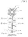
- Fig. 1 and Fig. 2 which is a side view of Fig. 1, bearings 6 and 8 are fitted to a pair of side plates, and a rotation shaft 10 is supported rotatively by the bearings 6 and 8.
- a cylindrical rotation body 12 serving as a rotor is fastened to the rotation shaft 10.
- the rotation shaft 10 is designed so as to be driven rotatively by a piezoelectric rotation driving apparatus 14 which contacts with the cylindrical rotation body 12.
- the piezoelectric rotation driving apparatus 14 is composed of a set of piezoelectric driving bodies 18 and 20, and leaf springs 22 and 24.
- the piezoelectric driving bodies 18 and 20 are bundled by a fitting pin 16 so that acting directions of forces produced by bodies 18 and 20 are oriented in opposite directions.
- the leaf springs 22 and 24 serve as an elastic member for thrusting each of the piezoelectric driving bodies 18 and 20 to the cylindrical rotation body 12.
- the respective piezoelectric driving bodies 18 and 20 are composed of action members 26 and 26 contacting with the outer surface of the cylindrical rotation body 12, base members 28 and 28 of approximately L character-shaped supporting the action members 26 and 26 rotatively, and stacked type piezoelectric elements 30 and 30 driving the action members 26 and 26 .
- the side surfaces of the action members 26 and 26 are formed so as to be approximately a triangular shape, and action surfaces 26a and 26a which contact directly with the outer surface 12a of the cylindrical rotation body 12 are formed at one apex of the triangles ( action points C and C ), the action surfaces 26a and 26a being formed so as to be a rectangular plain surface.
- fulcrums A and A are connected to the top ends of the vertical blade members 28a and 28a of the base members 28 and 28 by hinges 32 and 32 so that the action surfaces 26a and 26a are allowed to move rotatively.
- the stacked type piezoelectric elements 30 and 30 are disposed along the vertical blade portions 28a and 28a of the base members 28 and 28 .
- the top portions of the element 30 and 30 are connected to the residual apexes ( force points B and B ) by hinges 36 and 36 interposing seat members 34 and 34 between the hinges 36 and 36 and the element 30 and 30 .
- the bottom portions of the stacked type piezoelectric elements 30 and 30 are connected to horizontal blade portions 28b and 28b of the base members 28 and 28 by hinges 40 and 40 interposing seat members 38 and 38 between the hinges 40 and 40 and the elements 30 and 30 .
- through holes 28c and 28c are penetrated in the horizontal blade portions 28b and 28b' of the base members 28 and 28 of the piezoelectric driving bodies 18 and 20, the holes 28c and 28c being located on the same axis.
- the action surfaces 26a and 26a of the piezoelectric driving bodies 18 and 20 are disposed on the same line.
- the piezoelectric driving bodies 18 and 20 are integrated with each other by inserting the fitting pin 16 to the through holes 28c and 28c .
- the piezoelectric driving bodies 18 and 20 are arranged in parallel with the central axis line of the cylindrical rotation body 12 while the rotational displacement directions of the cylindrical rotation body 12 ( action direction of force ) are inverse to each other.
- the action surfaces 26a and 26a are thrust toward of the axis of the cylindrical rotation body 12 with an elastic force of the leaf springs 22 and 24.
- each of the piezoelectric driving bodies 18 and 20 are manufactured in manufacturing processes as an unit and adapted to the apparatus simply reversing one to the other.
- a rotation driving function of the piezoelectric rotation driving apparatus 14 will be described below, with reference to Figs. 4 to 8 which illustrate a principle of operations.
- the force produced by the stacked type piezoelectric element 30 acts on the force point B in the arrow line direction D 1 .
- the action member 26 rotates toward the arrow line D 2 ( counterclockwise ) around the fulcrum A.
- the cylindrical rotation body12 rotates toward the arrow line D 3 with a friction force applied from the action point C.
- the action surface 26a performs the rotational movement.
- the voltage applied to the stacked type piezoelectric incorporated in the set of the piezoelectric driving bodies 18 and 20 in this embodiment are two pulse rows P 1 and P 2 , the phases of the pulse rows P 1 and P 2 being shifted from each other.
- the two voltages serve to expand the stacked type piezoelectric elements 30 and 30'.
- the stacked type piezoelectric elements 30 and 30' produce the forces to expand and contract themself in proportion to the peaks of the voltage pulses, respectively.
- Each of the response characteristics of the elements due to the voltage application is different. However, it is possible to make the response characteristics even more precisely by adjusting the peak values Va and Vb of the voltage pulses shown in Fig. 9.
- the stacked type piezoelectric elements 30 and 30' require the time to response fully from the application of the voltages. This time, i.e., the response time constant, is obtained as the product of the electric capacitance of the stacked type piezoelectric elements 30 and 30' and the output impedance of the power source for generating the voltage pulse.
- the delay time Td of the pulse row P 2 against the pulse row P 1 shown in Fig. 9 should be far longer than the response time constant of the stacked type piezoelectric elements 30 and 30'.
- the stacked type piezoelectric elements 30 and 30' are such designed that when the time has passed by half of the period of the voltage application to the stacked type piezoelectric element 30 from the beginning of the voltage application to the element 30, the predetermined voltage is applied to the stacked type piezoelectric element 30'.
- the widths Ta and Tb of the voltage pulse are set longer than the delay time Td and they are set equal to each other.
- the aforementioned voltage pulse rows P 1 and P 2 can be realized by voltage applying means constituted by using an ordinary electric circuit technology.
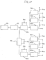
- An example of the circuit constitution of this voltage applying means is shown in Fig. 10.
- a vibrating voltage having a high recurrency frequency which is provided from an oscillating circuit 50, is converted to a vibrating voltage having a predetermined frequency by a frequency dividing circuit 52.
- a pulse shaping circuit 54a uses a voltage variation as a trigger, which is a rise-up or a decay of the output voltage from the frequency dividing circuit 52, and produces voltage pulses having a predetermined time width.
- a monostable multivibrator may be used as the pulse shaping circuit 54a.
- the time width of the voltage pulses is determined by adjusting an external resistor Rta which constitutes a time constant circuit.
- a delay circuit 56 delays the output voltage from the frequency dividing circuit 52.
- a pulse shaping circuit 54b uses the voltage variation delayed by the delay circuit 56 as a trigger, which is a rise-up or a decay of the output voltage.
- the pulse shaping circuit 54b produces voltage pulses having a predetermined time width.
- the delay time of the delay circuit 56 is determined by adjusting an external resistor Rd which constitutes a time constant circuit.
- the time width of the voltage pulses produced from the pulse shaping circuit 54b is determined by adjusting an external resistor Rtb which constituted a time constant circuit.
- Output pulses from the pulse shaping circuits 54a and 54b are applied to respective driving circuit 58a, 58b, ...., 58n and 60a, 60b,....60n and prepared to the voltage pulses having a predetermined peak value. Thereafter, the voltage pulses are applied to the stacked type piezoelectric elements 30 and 30' via output impedances.
- AE0203D08 manufactured by Nihon Electric Co. Ltd. was used as the stacked type piezoelectric 30 and 30'.
- the piezoelectric driving bodies 18 and 20 were pressed against the outer surface 12a of the cylindrical rotation body 12 by the leaf springs 22 and 24 with the force of 10 kgf and the voltage pulses of the peak value 50V, the width 500 ⁇ m, and the recurrency frequency 1 kHz were applied to the stacked type piezoelectric element 30.
- the response time of the stacked type piezoelectric element 30 was about 150 ⁇ sec.
- the element 30 expanded by about 4.5 ⁇ m.
- the action point C moved upward by about 4.5 ⁇ m, and moved toward the left direction by about 8 ⁇ m.
- the cylindrical rotation body 12 rotated by about 8 ⁇ m that is the distance at the surface of the rotation body 12.
- the other voltage pulse row P 2 delayed by 250 ⁇ sec as compared with the aforementioned voltage pulse row P 1 was applied to the stacked type piezoelectric element 30'.
- the stacked type piezoelectric element 30' expanded by 4.5 ⁇ m.
- the action point C' moved upward by about 4.5 ⁇ m, and moved toward the right direction about 8 ⁇ m.
- the cylindrical rotation body 12 rotated by about 8 ⁇ m that is the distance at the surface of the rotation body 12.
- the cylindrical rotation body 12 began to continue the rotation virtually at the number of the rotation of 15 r.p.m..
- the output torque was as high as about 2 kgf ⁇ cm, not depending on the rotation speed.
- the aforementioned number of the rotation is in inverse proportion to the diameter of the cylindrical rotation body 12, and in proportion to the recurrency frequency of the voltage pulses.
- the piezoelectric rotation driving apparatus 14 of the present invention has the definite feature that it is able to perform a small angle control with a high torque.
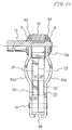
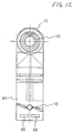
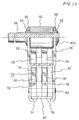
- Figs. 11 and 12 ( side view of Fig. 11 ) illustrate a piezoelectric rotation driving apparatus of a second embodiment of the present invention, wherein the leaf springs 22 and 24 as the elastic member in the first foregoing embodiment are altered.
- the piezoelectric rotation driving apparatus 14 has such structure that a set of piezoelectric driving bodies 18 and 20 are held with side plates 62 and 64 including bending portions 62a and 64a, and action surfaces 26a and 26a' are pressed against an outer surface 12a of a cylindrical rotation body 12 with the forces produced by the bending portions 62a and 64a.
- Reference numerals 66 and 68 denote a supporting plate. It should be noted that a various kind of spring members such as a coil spring and the like may be employed as an elastic member for producing a pressing force.
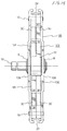
- Fig. 13 illustrates a piezoelectric rotating driving apparatus of a third embodiment of the present invention, wherein in order to increase an output torque, plural sets of piezoelectric driving bodies incorporated in the apparatus are disposed along the center axis of a rotor.
- the piezoelectric rotation driving apparatus 70 is composed of piezoelectric driving bodies 72, 74, 76, and 78 having the same constitution as those of the foregoing embodiments, a leaf spring 82 pressing these piezoelectric driving bodies 72, 74, 76, and 78 against an outer surface of a cylindrical rotation body 80, and a fitting pin 84 serving as an integrating member.
- Reference numerals 86 and 88 denote a side plate; 90 and 92, a bearing; and 94, a rotating shaft.
- the piezoelectric rotation driving apparatus 70 of the third embodiment of the present invention uses first and second sets of the piezoelectric driving bodies 72, 74, 76, and 78.
- the first set is composed of the piezoelectric driving bodies 72 and 74
- the second set is composed of the piezoelectric driving bodies 76 and 78.
- the first set produces a force acting on in one direction
- the second set produces a force acting on in an inverse direction to that produced by the first set.
- the piezoelectric driving bodies are arranged such that the piezoelectric driving bodies in the same set produce a force acting on in the same direction and the piezoelectric driving bodies in different set produce a force acting on in an inverse direction.
- the number of the piezoelectric driving bodies may be increased.
- the driving power is increased in proportion to the number of the piezoelectric driving bodies simultaneously driven, and the output torque increases in proportion to the driving power.
- the number of the piezoelectric driving bodies should be preferably the same in each of the sets. Because in the case where the number of the piezoelectric driving bodies is different among the sets, the maximum load is determined according to the driving force of the set having less piezoelectric driving bodies, so that the driving power of the set having more piezoelectric driving bodies can not be effectively utilized.
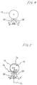
- Fig. 4 illustrates a fourth embodiment of a piezoelectric rotation driving apparatus of the present invention, wherein plural sets of piezoelectric driving bodies are arranged around a rotor.
- a piezoelectric rotation driving apparatus 96 in the fourth embodiment is composed of a set of piezoelectric driving bodies 98 and 100 pressed by a leaf spring 22 against a cylindrical rotation body 12, and a set of piezoelectric driving bodies 102 and 104 arranged around the cylindrical rotation body 12, the bodies 102 and 104 being in the opposite position to the piezoelectric driving bodies 98 and 100 in a direction of a diameter of the cylindrical rotation body 12.
- the piezoelectric driving bodies 102 and 104 are pressed by a leaf spring 24 against the cylindrical rotation body 12.
- the structure of each of the piezoelectric driving bodies is the same as that of the piezoelectric driving bodies in the foregoing embodiments.
- Reference numerals 106 and 108 denote a side plate.
- the piezoelectric driving bodies 98 and 100 produce the forces acting on in the same direction along the circumference of the circle of the cylindrical rotation body 12, and are driven at the same timing.
- the piezoelectric driving bodies 100 and 104 also produce the forces and are driven, in the same manner as in the piezoelectric driving bodies 98 and 100.
- the rotation output can be obtained according to the similar operation principle to the foregoing embodiments.
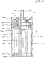
- Figs. 15 and 16 sectional view taken along the line Y-Y of Fig. 15
- these piezoelectric driving bodies 112, 114, 116, and 118 are illustrated with the dotted lines, for convenience of the understanding of the structure of the piezoelectric rotation driving apparatus 110 of the embodiment of the present invention.
- the piezoelectric rotation driving apparatus 110 is composed of piezoelectric driving bodies 112, 114, 116, and 118, and belleville springs 138a and 138b serving as an elastic member for pressing the piezoelectric driving bodies 112, 124, 116, and 118 against a flange portion 128 of a rotation shaft 126 serving as a rotor.
- Each of the piezoelectric driving bodies 112, 114, 116, and 118 is arranged on a disk-shaped seat member 122 integrated with a central bearing 120 at the positions symmetrical to the center axis of the bearing 120.
- the rotor 124 is formed of the rotation shaft 126 and a flange portion 128 extending from the rotation shaft 126 approximately perpendicular thereto, the rotation shaft 126 and the flange portion 128 being integrated with each other.
- the one end of the rotation shaft 126 is supported by the central bearing 120 via a bush 129, and the other end is supported by a housing bearing 132 via bush 130.
- a nail portion of a housing member 134 is fastened to the seat member 122.
- two belleville springs 138a and 138b inserted between the housing bearing 132 and the flange portion 128 are changed to a crushed state by a predetermined dimension.
- the crushed belleville springs 138a and 138b produce a pressurizing force acting between the side plane 128a of the flange portion 128 and the piezoelectric driving bodies 112, 114, 116, and 118 via a bearing 140.
- two piezoelectric driving bodies 112 and 114 are arranged such that the action directions of the action points thereof are in the directions illustrated by the arrow D 8 and D 9 ( clockwise ).
- the other piezoelectric driving bodies 116 and 118 are arranged such that the action directions of the action points thereof are in the directions illustrated by the arrow D 10 and D 11 ( counterclockwise ).
- by driving simultaneously the piezoelectric driving bodies wherein the action directions of the action points are in the same direction it is possible to rotate the flange portion 128, that is, the rotation shaft 126.
- the housing bearing 132, the central bearing 120, and the rotation shaft 126 should be worked precisely so that the relative positional relations thereof to the bushes 129 and 130 are not broken down.
- the shapes and the arrangements of each of the components constituting the piezoelectric rotation driving apparatus of the present invention are specified.
- the present invention is not limited to the above shapes and the arrangements. It should be understood that the piezoelectric driving apparatus of the present invention can be modified appropriately in a scope satisfying the stable and high torque function without the foregoing inertia rotation period.
- the excitation energy of the piezoelectric element can be transferred to the rotation of the rotor with high efficiency, the inertia rotation period where the rotor is thrust up by the piezoelectric driving body and separates therefrom. Therefore, a torque with a high efficiency and a stability can be obtained.
- the piezoelectric rotation driving apparatus of the present invention employs a lever principle losing littler power, the constitution is simple and the number of the piezoelectric elements is small. Therefore, miniaturization of size of the apparatus and high torque of the apparatus can be realized.
Landscapes
- General Electrical Machinery Utilizing Piezoelectricity, Electrostriction Or Magnetostriction (AREA)
Applications Claiming Priority (3)
| Application Number | Priority Date | Filing Date | Title |
|---|---|---|---|
| JP32622394 | 1994-12-27 | ||
| JP6326223A JP2658930B2 (ja) | 1994-12-27 | 1994-12-27 | 圧電型回転駆動装置 |
| JP326223/94 | 1994-12-27 |
Publications (3)
| Publication Number | Publication Date |
|---|---|
| EP0720245A2 true EP0720245A2 (fr) | 1996-07-03 |
| EP0720245A3 EP0720245A3 (fr) | 1998-04-15 |
| EP0720245B1 EP0720245B1 (fr) | 2001-05-16 |
Family
ID=18185369
Family Applications (1)
| Application Number | Title | Priority Date | Filing Date |
|---|---|---|---|
| EP95120600A Expired - Lifetime EP0720245B1 (fr) | 1994-12-27 | 1995-12-27 | Appareil d'entraínement rotatif piézo-électrique |
Country Status (5)
| Country | Link |
|---|---|
| US (1) | US5712524A (fr) |
| EP (1) | EP0720245B1 (fr) |
| JP (1) | JP2658930B2 (fr) |
| KR (1) | KR100206083B1 (fr) |
| DE (1) | DE69520931T2 (fr) |
Cited By (1)
| Publication number | Priority date | Publication date | Assignee | Title |
|---|---|---|---|---|
| FR2913829A1 (fr) * | 2007-03-14 | 2008-09-19 | Cedrat Technologies Sa | Systeme de positionnement fin par moteur inertiel a base d'amplificateur mecanique |
Families Citing this family (57)
| Publication number | Priority date | Publication date | Assignee | Title |
|---|---|---|---|---|
| US6040653A (en) * | 1996-10-17 | 2000-03-21 | Kinetic Ceramics, Inc. | Piezoelectric positioner |
| JP3638745B2 (ja) * | 1997-02-07 | 2005-04-13 | 富士重工業株式会社 | ロータリスポイラ付ロータブレード |
| JPH10337057A (ja) * | 1997-06-02 | 1998-12-18 | Minolta Co Ltd | 駆動装置 |
| US5903085A (en) * | 1997-06-18 | 1999-05-11 | Phase Metrics, Inc. | Piezoelectric nanopositioner |
| JP2002354853A (ja) * | 1997-08-04 | 2002-12-06 | Seiko Epson Corp | アクチュエータ、およびそれを用いた時計並びに報知装置 |
| CN1241322A (zh) * | 1997-08-04 | 2000-01-12 | 精工爱普生株式会社 | 传动装置及使用它的钟表和通知装置 |
| DE19909913B4 (de) * | 1999-03-06 | 2004-01-15 | NMI Naturwissenschaftliches und Medizinisches Institut an der Universität Tübingen | Elektromechanische Antriebsvorrichtung |
| US6836056B2 (en) | 2000-02-04 | 2004-12-28 | Viking Technologies, L.C. | Linear motor having piezo actuators |
| DE10010707C2 (de) * | 2000-03-04 | 2002-01-10 | Philips Corp Intellectual Pty | Piezoelektrischer Aktuator |
| US6437226B2 (en) | 2000-03-07 | 2002-08-20 | Viking Technologies, Inc. | Method and system for automatically tuning a stringed instrument |
| US6717332B2 (en) | 2000-04-18 | 2004-04-06 | Viking Technologies, L.C. | Apparatus having a support structure and actuator |
| US6548938B2 (en) * | 2000-04-18 | 2003-04-15 | Viking Technologies, L.C. | Apparatus having a pair of opposing surfaces driven by a piezoelectric actuator |
| SG92724A1 (en) * | 2000-07-24 | 2002-11-19 | Inst Data Storage | Head suspension assembly with piezoelectric beam micro actuator |
| US6936951B1 (en) | 2000-11-27 | 2005-08-30 | Grq Instruments, Inc. | Smart sonic bearings and method for frictional force reduction and switching |
| US6879087B2 (en) * | 2002-02-06 | 2005-04-12 | Viking Technologies, L.C. | Apparatus for moving a pair of opposing surfaces in response to an electrical activation |
| US6759790B1 (en) | 2001-01-29 | 2004-07-06 | Viking Technologies, L.C. | Apparatus for moving folded-back arms having a pair of opposing surfaces in response to an electrical activation |
| US7207946B2 (en) * | 2002-05-09 | 2007-04-24 | Spiration, Inc. | Automated provision of information related to air evacuation from a chest cavity |
| USD493416S1 (en) | 2002-06-19 | 2004-07-27 | Viking Technologies, L.C. | Integral actuator with force transfer member |
| USD483335S1 (en) | 2002-06-19 | 2003-12-09 | Viking Technologies, L.C. | Integral actuator with folded-back arms |
| USD494923S1 (en) | 2002-06-19 | 2004-08-24 | Viking Technologies, L.C. | Integral force transfer member |
| WO2004001871A2 (fr) * | 2002-06-21 | 2003-12-31 | Viking Technologies, L.C. | Moteur piezo-electrique monobloc |
| US6973701B2 (en) * | 2002-10-19 | 2005-12-13 | General Motors Corporation | Releasable fastening system based on ionic polymer metal composites and method of use |
| JP4015983B2 (ja) * | 2002-10-19 | 2007-11-28 | ゼネラル・モーターズ・コーポレーション | 解除可能な付属品用の磁気粘性ナノ複合エラストマー |
| US6815873B2 (en) * | 2002-10-19 | 2004-11-09 | General Motors Corporation | Releasable fastener system |
| US7013538B2 (en) | 2002-10-19 | 2006-03-21 | General Motors Corporation | Electroactive polymer releasable fastening system and method of use |
| US7146690B2 (en) * | 2002-10-19 | 2006-12-12 | General Motors Corporation | Releasable fastener system |
| US6983517B2 (en) * | 2002-10-19 | 2006-01-10 | General Motors Corporation | Releasable fastener system |
| US7013536B2 (en) | 2002-10-19 | 2006-03-21 | General Motors Corporation | Releasable fastener systems and processes |
| US7140081B2 (en) * | 2002-10-19 | 2006-11-28 | General Motors Corporation | Releasable fastener system |
| US7308738B2 (en) * | 2002-10-19 | 2007-12-18 | General Motors Corporation | Releasable fastener systems and processes |
| US7032282B2 (en) | 2002-10-19 | 2006-04-25 | General Motors Corporation | Releasable fastener system |
| US6944920B2 (en) * | 2002-10-19 | 2005-09-20 | General Motors Corporation | Electrostatically releasable fastening system and method of use |
| USD493417S1 (en) | 2002-12-10 | 2004-07-27 | Viking Technologies, L.C. | Folded back arm actuator |
| USD496330S1 (en) | 2002-12-10 | 2004-09-21 | Viking Technologies, L.C. | Integral actuator with hollowed out force transfer member |
| USD493135S1 (en) | 2002-12-10 | 2004-07-20 | Viking Technologies, L.C. | Integral actuator with folded back arms and hollowed out force transfer member |
| CA2521307C (fr) | 2003-04-04 | 2014-07-15 | Viking Technologies, L.C. | Appareil et processus d'optimisation du travail a partir d'un dispositif de commande materiel intelligent |
| USD512085S1 (en) | 2003-06-06 | 2005-11-29 | Viking Technologies, L.C. | Folded back arm actuator with enlarged central anvil |
| US7219113B2 (en) * | 2003-09-26 | 2007-05-15 | International Business Machines Corporation | Pseudo-random binary sequence checker with automatic synchronization |
| JP2005287167A (ja) * | 2004-03-29 | 2005-10-13 | Konica Minolta Opto Inc | 駆動装置 |
| US20060261109A1 (en) * | 2005-05-18 | 2006-11-23 | Browne Alan L | Cargo container including an active material based releasable fastener system |
| JP2007049880A (ja) * | 2005-08-12 | 2007-02-22 | Fujinon Corp | アクチュエータ |
| JP4767726B2 (ja) * | 2006-03-13 | 2011-09-07 | 富士フイルム株式会社 | 超音波アクチュエータ |
| JP2007274746A (ja) * | 2006-03-30 | 2007-10-18 | Fujinon Corp | 駆動装置 |
| US7432637B2 (en) * | 2006-07-28 | 2008-10-07 | Neuberg Company Limited | Piezoelectric drive device and liquid discharging device |
| JP4994126B2 (ja) * | 2006-07-28 | 2012-08-08 | ノイベルク有限会社 | 圧電駆動装置および液体吐出装置 |
| US7872397B2 (en) * | 2006-12-20 | 2011-01-18 | The Boeing Company | Electrical to mechanical energy converter |
| JP2009136135A (ja) * | 2007-11-08 | 2009-06-18 | Taiyo Yuden Co Ltd | 圧電駆動装置 |
| JP5835212B2 (ja) * | 2010-03-31 | 2015-12-24 | 株式会社ニコン | モータ装置、モータ装置の製造方法及びロボット装置 |
| USD678834S1 (en) * | 2010-12-07 | 2013-03-26 | Daishinku Corporation | Tuning fork type piezoelectric resonator device |
| USD678835S1 (en) * | 2011-05-09 | 2013-03-26 | Daishinku Corporation | Tuning-fork type piezoelectric resonator device |
| DE102011109590A1 (de) * | 2011-08-05 | 2013-02-07 | Physik Instrumente (Pi) Gmbh & Co. Kg | Piezoelektrischer Drehantrieb für eine Welle |
| DE102015208591B4 (de) * | 2015-05-08 | 2016-12-08 | Physik Instrumente (Pi) Gmbh & Co. Kg | Piezoelektrischer Drehantrieb mit einem als Blattfeder ausgebildeten Spannmittel |
| CN107046380B (zh) * | 2017-02-23 | 2019-04-19 | 南京航空航天大学 | 一种多辐条型超声电机 |
| CN108092549B (zh) * | 2018-01-12 | 2020-01-10 | 长春工业大学 | 紧凑型精密压电粘滑升降平台及其驱动方法 |
| CN112152507B (zh) * | 2020-08-25 | 2021-12-21 | 江苏大学 | 一种可变步进角度的冲击式压电旋转马达 |
| CN114257125A (zh) * | 2022-01-04 | 2022-03-29 | 长春工业大学 | 正交菱形双模式精密压电粘滑旋转平台及其驱动方法 |
| CN115106143A (zh) * | 2022-06-29 | 2022-09-27 | 合肥瀚海星点生物科技有限公司 | 一种高精度电动微量液体移液器 |
Family Cites Families (15)
| Publication number | Priority date | Publication date | Assignee | Title |
|---|---|---|---|---|
| US4622483A (en) * | 1983-03-24 | 1986-11-11 | Staufenberg Jr Charles W | Piezoelectric electromechanical translation apparatus and method |
| US4613782A (en) * | 1984-03-23 | 1986-09-23 | Hitachi, Ltd. | Actuator |
| JPS61258679A (ja) * | 1985-05-07 | 1986-11-17 | Nec Corp | 回転角制御装置 |
| JPH0410704Y2 (fr) * | 1987-04-20 | 1992-03-17 | ||
| JPS6412878A (en) * | 1987-07-02 | 1989-01-17 | Hitachi Metals Ltd | Piezoelectric actuator |
| US4769569A (en) * | 1988-01-19 | 1988-09-06 | Ford Motor Company | Piezoelectric stack motor stroke amplifier |
| JP2577423B2 (ja) * | 1988-02-29 | 1997-01-29 | 工業技術院長 | 大ストローク走査型トンネル顕微鏡 |
| JPH0267772A (ja) * | 1988-09-01 | 1990-03-07 | Mitsubishi Electric Corp | 圧電駆動装置 |
| JPH0295180A (ja) * | 1988-09-29 | 1990-04-05 | Canon Inc | 尺取り虫型駆動機構 |
| JPH0688680B2 (ja) * | 1989-03-20 | 1994-11-09 | 輝 林 | 記録媒体搬送装置及びこの装置に用いられる圧電素子付枠体 |
| JPH0382379A (ja) * | 1989-08-24 | 1991-04-08 | Nec Corp | 微小回転モータ |
| JPH03273871A (ja) * | 1990-03-22 | 1991-12-05 | Nec Corp | 圧電モータ |
| US5282404A (en) * | 1990-11-09 | 1994-02-01 | The Government Of The United States Of America As Represented By The Secretary Of The Dept. Of Health & Human Services | Microtome with micro-plane and electric contact reference |
| EP0592030B1 (fr) * | 1992-10-02 | 1998-05-20 | Koninklijke Philips Electronics N.V. | Dispositif de déplacement électromécanique et organe d'action apte à être utilisé dans un tel dispositif |
| JP3040896U (ja) * | 1997-02-24 | 1997-09-05 | 雄亨 斉藤 | 空気層をもった活性炭入り靴用底敷 |
-
1994
- 1994-12-27 JP JP6326223A patent/JP2658930B2/ja not_active Expired - Lifetime
-
1995
- 1995-12-26 US US08/578,320 patent/US5712524A/en not_active Expired - Fee Related
- 1995-12-27 EP EP95120600A patent/EP0720245B1/fr not_active Expired - Lifetime
- 1995-12-27 DE DE69520931T patent/DE69520931T2/de not_active Expired - Fee Related
- 1995-12-27 KR KR1019950059771A patent/KR100206083B1/ko not_active Expired - Fee Related
Cited By (3)
| Publication number | Priority date | Publication date | Assignee | Title |
|---|---|---|---|---|
| FR2913829A1 (fr) * | 2007-03-14 | 2008-09-19 | Cedrat Technologies Sa | Systeme de positionnement fin par moteur inertiel a base d'amplificateur mecanique |
| WO2008132337A3 (fr) * | 2007-03-14 | 2009-01-29 | Cedrat Technologies | Système de positionnement fin par moteur inertiel à base d'amplificateur mécanique |
| US8004153B2 (en) | 2007-03-14 | 2011-08-23 | Cedrat Technologies | Fine positioning system using an inertial motor based on a mechanical amplifier |
Also Published As
| Publication number | Publication date |
|---|---|
| KR100206083B1 (ko) | 1999-07-01 |
| KR960027218A (ko) | 1996-07-22 |
| DE69520931T2 (de) | 2002-01-17 |
| EP0720245B1 (fr) | 2001-05-16 |
| DE69520931D1 (de) | 2001-06-21 |
| JP2658930B2 (ja) | 1997-09-30 |
| EP0720245A3 (fr) | 1998-04-15 |
| JPH08182360A (ja) | 1996-07-12 |
| US5712524A (en) | 1998-01-27 |
Similar Documents
| Publication | Publication Date | Title |
|---|---|---|
| EP0720245B1 (fr) | Appareil d'entraínement rotatif piézo-électrique | |
| US6252332B1 (en) | Ultrasonic motor | |
| RU2179363C2 (ru) | Пьезоэлектрический привод или двигатель, способ приведения его в действие и способ его изготовления | |
| US5079471A (en) | High torque harmonic traction motor | |
| US5668432A (en) | Articulation device | |
| US5747915A (en) | Bent shaft motor | |
| US20090127974A1 (en) | Small piezoelectric or electrostrictive linear motor | |
| JPS61224886A (ja) | 電気機械的な装置 | |
| JPH10337057A (ja) | 駆動装置 | |
| JPS62171457A (ja) | リニア・アクチユエ−タ | |
| US6265810B1 (en) | Piezoelectric support device | |
| JPH05316757A (ja) | 移動機構 | |
| WO1992020141A1 (fr) | Moteur a ultrasons | |
| EP0469883A2 (fr) | Moteur actionné par vibrations | |
| JP2998978B2 (ja) | 振動波装置および駆動装置 | |
| Smits et al. | The effectiveness of a piezoelectric bimorph actuator to perform mechanical work under various constant loading conditions | |
| JP2001186781A (ja) | 振動アクチュエータ | |
| GB2354046A (en) | Linear bearing | |
| JP3168843B2 (ja) | 駆動装置 | |
| JPH06284752A (ja) | 超音波モータ | |
| JPH07255189A (ja) | 超音波アクチュエータ | |
| JP4550620B2 (ja) | 圧電アクチュエータおよびそれを用いた電子機器 | |
| JPH07308083A (ja) | 移動機構及びその駆動方法 | |
| JP3005093B2 (ja) | 並進回転振動変換器 | |
| CN110138262B (zh) | 一种单激励源双向作动的直线超声电机 |
Legal Events
| Date | Code | Title | Description |
|---|---|---|---|
| PUAI | Public reference made under article 153(3) epc to a published international application that has entered the european phase |
Free format text: ORIGINAL CODE: 0009012 |
|
| AK | Designated contracting states |
Kind code of ref document: A2 Designated state(s): DE FR GB IT NL |
|
| PUAL | Search report despatched |
Free format text: ORIGINAL CODE: 0009013 |
|
| AK | Designated contracting states |
Kind code of ref document: A3 Designated state(s): DE FR GB IT NL |
|
| 17P | Request for examination filed |
Effective date: 19980306 |
|
| 17Q | First examination report despatched |
Effective date: 19990217 |
|
| GRAG | Despatch of communication of intention to grant |
Free format text: ORIGINAL CODE: EPIDOS AGRA |
|
| GRAG | Despatch of communication of intention to grant |
Free format text: ORIGINAL CODE: EPIDOS AGRA |
|
| GRAH | Despatch of communication of intention to grant a patent |
Free format text: ORIGINAL CODE: EPIDOS IGRA |
|
| GRAH | Despatch of communication of intention to grant a patent |
Free format text: ORIGINAL CODE: EPIDOS IGRA |
|
| GRAA | (expected) grant |
Free format text: ORIGINAL CODE: 0009210 |
|
| AK | Designated contracting states |
Kind code of ref document: B1 Designated state(s): DE FR GB IT NL |
|
| REF | Corresponds to: |
Ref document number: 69520931 Country of ref document: DE Date of ref document: 20010621 |
|
| ITF | It: translation for a ep patent filed | ||
| ET | Fr: translation filed | ||
| PGFP | Annual fee paid to national office [announced via postgrant information from national office to epo] |
Ref country code: FR Payment date: 20011218 Year of fee payment: 7 |
|
| PGFP | Annual fee paid to national office [announced via postgrant information from national office to epo] |
Ref country code: GB Payment date: 20011227 Year of fee payment: 7 |
|
| PGFP | Annual fee paid to national office [announced via postgrant information from national office to epo] |
Ref country code: NL Payment date: 20011228 Year of fee payment: 7 |
|
| REG | Reference to a national code |
Ref country code: GB Ref legal event code: IF02 |
|
| PGFP | Annual fee paid to national office [announced via postgrant information from national office to epo] |
Ref country code: DE Payment date: 20020219 Year of fee payment: 7 |
|
| PLBE | No opposition filed within time limit |
Free format text: ORIGINAL CODE: 0009261 |
|
| STAA | Information on the status of an ep patent application or granted ep patent |
Free format text: STATUS: NO OPPOSITION FILED WITHIN TIME LIMIT |
|
| 26N | No opposition filed | ||
| PG25 | Lapsed in a contracting state [announced via postgrant information from national office to epo] |
Ref country code: GB Free format text: LAPSE BECAUSE OF NON-PAYMENT OF DUE FEES Effective date: 20021227 |
|
| PG25 | Lapsed in a contracting state [announced via postgrant information from national office to epo] |
Ref country code: NL Free format text: LAPSE BECAUSE OF NON-PAYMENT OF DUE FEES Effective date: 20030701 Ref country code: DE Free format text: LAPSE BECAUSE OF NON-PAYMENT OF DUE FEES Effective date: 20030701 |
|
| GBPC | Gb: european patent ceased through non-payment of renewal fee |
Effective date: 20021227 |
|
| NLV4 | Nl: lapsed or anulled due to non-payment of the annual fee |
Effective date: 20030701 |
|
| PG25 | Lapsed in a contracting state [announced via postgrant information from national office to epo] |
Ref country code: FR Free format text: LAPSE BECAUSE OF NON-PAYMENT OF DUE FEES Effective date: 20030901 |
|
| REG | Reference to a national code |
Ref country code: FR Ref legal event code: ST |
|
| PG25 | Lapsed in a contracting state [announced via postgrant information from national office to epo] |
Ref country code: IT Free format text: LAPSE BECAUSE OF NON-PAYMENT OF DUE FEES Effective date: 20051227 |