EP0720398A2 - Schnurloser Selektivrufempfänger - Google Patents
Schnurloser Selektivrufempfänger Download PDFInfo
- Publication number
- EP0720398A2 EP0720398A2 EP95309421A EP95309421A EP0720398A2 EP 0720398 A2 EP0720398 A2 EP 0720398A2 EP 95309421 A EP95309421 A EP 95309421A EP 95309421 A EP95309421 A EP 95309421A EP 0720398 A2 EP0720398 A2 EP 0720398A2
- Authority
- EP
- European Patent Office
- Prior art keywords
- data
- transmission rate
- receiver
- transmitting
- section
- Prior art date
- Legal status (The legal status is an assumption and is not a legal conclusion. Google has not performed a legal analysis and makes no representation as to the accuracy of the status listed.)
- Withdrawn
Links
Images

Classifications
-
- H—ELECTRICITY
- H04—ELECTRIC COMMUNICATION TECHNIQUE
- H04B—TRANSMISSION
- H04B10/00—Transmission systems employing electromagnetic waves other than radio-waves, e.g. infrared, visible or ultraviolet light, or employing corpuscular radiation, e.g. quantum communication
- H04B10/60—Receivers
- H04B10/66—Non-coherent receivers, e.g. using direct detection
-
- H—ELECTRICITY
- H04—ELECTRIC COMMUNICATION TECHNIQUE
- H04W—WIRELESS COMMUNICATION NETWORKS
- H04W8/00—Network data management
- H04W8/22—Processing or transfer of terminal data, e.g. status or physical capabilities
- H04W8/24—Transfer of terminal data
- H04W8/245—Transfer of terminal data from a network towards a terminal
-
- G—PHYSICS
- G08—SIGNALLING
- G08B—SIGNALLING SYSTEMS, e.g. PERSONAL CALLING SYSTEMS; ORDER TELEGRAPHS; ALARM SYSTEMS
- G08B3/00—Audible signalling systems, e.g. audible personal calling systems
- G08B3/10—Audible signalling systems, e.g. audible personal calling systems using electric transmission; using electromagnetic transmission
- G08B3/1008—Personal calling arrangements or devices, i.e. paging systems
- G08B3/1016—Personal calling arrangements or devices, i.e. paging systems using wireless transmission
- G08B3/1025—Paging receivers with audible signalling details
- G08B3/1066—Paging receivers with audible signalling details with other provisions not elsewhere provided for, e.g. turn-off protection
-
- H—ELECTRICITY
- H04—ELECTRIC COMMUNICATION TECHNIQUE
- H04W—WIRELESS COMMUNICATION NETWORKS
- H04W88/00—Devices specially adapted for wireless communication networks, e.g. terminals, base stations or access point devices
- H04W88/02—Terminal devices
- H04W88/022—Selective call receivers
Definitions
- the present invention relates to a wireless selective call receiver, and more particularly to data write in a wireless selective call receiver.
- a wireless selective call receiver (to be simply referred to as "receiver” hereinafter) or a pager has a connector via which the receiver is connected to an external apparatus.
- Data such as an ID number assigned to the receiver and data necessary for performing various functions of the receiver are transmitted from the external apparatus to the receiver via the connector and stored in the receiver.
- the connector since the connector is exposed from the receiver case, there is a problem in water-proof property and dust-proof property of the receiver.
- receivers or pagers are used between many persons.
- data such as an ID data assigned to the receiver and data necessary for performing various functions of the receiver need to be written in the receiver.
- the transmission rate is low in the data transmission using infrared light, there is a problem in that the work efficiency is low.
- An object of at least the preferred embodiments of the present invention is to provide a wireless selective call receiver in which desired data can be transmitted and written at a transmission rate as high as possible while suppressing any data error.
- Another such object is to provide a method and system for automatically transmitting and writing desired data in a wireless selective call receiver with a high transmission rate without wasting the data transmission time.
- a radio communication device comprising:
- a device for initialising a radio communication device comprising:
- a wireless selective call receiver comprising an optical transmitting section for optically transmitting data with a transmission rate, an optical receiving section for optically receiving data with the transmission rate, a storage section for storing receiver information, a program storage section for storing a program composed of an initial program, a data write program and a use program, and a control section for executing the initial program to control the transmitting section to optically transmit a predetermined data when the receiver is turned on, and to automatically initiate, when a response is received by the receiving section within a predetermined time period after the transmission of the predetermined data, the data write program:
- the control section may execute the data write program: (a) to set a predetermined transmission rate as a current transmission rate to the transmitting and receiving sections; (b) to control the transmitting section to transmit a test data having a predetermined bit pattern to the external apparatus with the current transmission rate; (c) to control the receiving section to receive a transmission ready signal from the external apparatus and then to receive the desired data, and to write the received data into the storage section; and (d) to control the receiving section to receive a transmission failure signal from the external apparatus ,and then to set a transmission rate lower than the current transmission rate as a new current transmission rate in the transmitting and receiving sections, and further to repeat the step (b) until the desired transmission rate is determined.
- the transmission rates are predetermined in a higher order and held in the receiver and the external apparatus.
- a data indicative of the transmission rate may be transmitted prior to the transmission of the test data.
- the data indicative of the transmission rate is transmitted with a predetermined transmission rate and the test data is transmitted with the transmission rate indicated by the data.
- the desired transmission rate is first determined through communicating between a wireless selective call receiver and a data transfer apparatus via an optical transmission path while changing a transmission rate. Then, the desired data is transmitted with the determined transmission rate from the data transmission apparatus to the selective call receiver via the optical transmission path such that the desired data is written in the receiver. After the write operation, it is verified that the desired data is accurately written in the receiver.
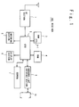
- Fig. 1 is a schematic block diagram showing the structure of the receiver according to an embodiment of the present invention. As shown in Fig.
- the receiver 100 includes, as major components, a RF section 1 for receiving a wireless selective call signal via an antenna, a ROM 3 having a transmission rate table 3-1, for storing a program and data indicative of transmission rates, a RAM 4 for storing a message contained in the received call signal, an informing section 5 operated to inform that the call signal to the receiver is received, a display section 6 for displaying a message, an EEPROM 7 for storing data such as an ID number assigned to the receiver and data for performing various functions of the receiver, and an infrared light interface section 8 for communicating with a data transfer apparatus 10.
- the receiver 100 further includes a CPU 2 for controlling various sections of the receiver 100.
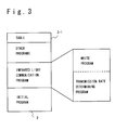
- Fig. 3 shows the content of the ROM 3.
- the ROM 3 stores a program composed of an initial program, infrared light communication program, and other programs such as application programs including a receiver functioning program and the transmission rate table 3-1.
- the initial program is executed by the CPU 2 when the receiver 100 is turned on by a switch (not shown).
- a signal indicative of a predetermined data is read out from the ROM 3 and externally transmitted by the infrared light interface section 8. If any response is not received within a predetermined time period after the signal is transmitted, the CPU 2 executes one of the other programs, e.g., the receiver functioning program.
- the CPU determines whether the call is destined to the receiver, using the ID number stored in the EEPROM 7.
- the CPU 2 drives the informing section 5 to execute an informing operation. Further, the CPU 2 stores a message contained in a signal following the call signal in the RAM 4 and makes the display section 6 to display the message, if necessary.
- the CPU 2 automatically executes the infrared light communication program which is composed of a transmission rate determining program and a write program.
- a desired transmission rate is determined based on the transmission rate determining program.
- the write program is automatically executed by the CPU 2 so that a desired data is transmitted from the data transfer apparatus 10 is written in the EEPROM 7. If the data cannot be accurately written in the EEPROM 7, the transmission rate determining program is again executed.
- Fig. 2 is the structures of the infrared light interface section and the data transfer apparatus 10.
- the infrared light interface section 8 is connected to the CPU 2 and is designed in such a manner that the operation is controlled by the CPU 2.
- the interface section 8 is composed of an infrared light emitting section 81, transmission drive circuit 82, infrared light receiving section 83, and received waveform amplifying & shaping circuit 84.
- the CPU 2 sets a data indicative of a transmission rate in the transmission drive circuit 82 and controls the circuit 82 such that the circuit 82 drives the infrared light emitting section 81 with the set transmission rate.
- the infrared light emitting section 81 includes an infrared light emitting element and is driven by the transmission drive circuit 82 such that photoelectric conversion is executed and a modulated infrared light as the result of the conversion is transmitted to the data transfer apparatus 10. Also, the CPU 2 sets the data indicative of the transmission rate in the amplifying & shaping circuit 82.
- the infrared light receiving section 83 includes an infrared light receiving element. The receiving section 83 receives the modulated infrared light transmitted from the data transfer apparatus 10 and converts it into an electric signal to supply to the received waveform amplifying & shaping circuit 84.
- the circuit 84 amplifies and shapes the electric signal to supply to the CPU 2. In this manner, the CPU 2 writes the desired data contained in the signal supplied from the received waveform amplifying & shaping circuit 84 in the EEPROM 7.
- the data transfer apparatus 10 is composed of a light receiving section 11 for receiving the infrared light emitted from the infrared light emitting section 81, a light emitting section 12 for emitting the infrared light to the infrared light receiving section 83, memory section 14 for storing the test data, table 15 for storing transmission rates which are predetermined between the receiver 100 and the data transfer apparatus 10 and the same as those stored in the table 3-1, indicator for indicating the end of a data write operation, and a control circuit 13 connected to the above-mentioned sections.
- the control circuit 13 is designed to make it possible to transmit and receive data to and from the receiver using the infrared light.
- This structure is substantially the same as the infrared light interface section 8 in the receiver 100 and therefore the description is omitted.
- the control section 13 reads out the test data from the memory section 14 to compares the read out test data with the test data received by the light receiving section 11 and issues a transmission ready signal when both the data is matched and a reception failure signal when both the data is not matched. Further, when both the data is not matched, the control section 13 reads out one of the transmission rates from the table 15 to set to the light receiving section 12 and the light emitting section 12.
- the CPU 2 automatically initiates the initial program to transmit a predetermined data through the infrared light interface section 8 with a predetermined low transmission rate.
- the CPU 2 automatically executes the other programs.
- the CPU 2 automatically executes the infrared light communication program.
- the data transfer apparatus 10 needs to be set in the above predetermined low transmission rate and replies the response to the receiver 100 in response to the reception of the predetermined data.
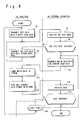
- the CPU 2 When the communication program is executed in response to the reception of the response in the receiver 100, in a step S2, the CPU 2 reads out a data indicative of the highest transmission rate from the table 3-1 of the ROM 3 and sets it in the circuits 82 and 84. Subsequently, the CPU 2 reads out a test data of one byte having a predetermined bit pattern from the ROM 3 to supply to the transmission drive circuit 82.
- the circuit 82 drives the infrared light emitting section 81 with the set transmission rate based on the test data supplied from the CPU 2 to produce and transmit an infrared light to the data transfer apparatus.
- the control section 13 reads out data indicative of the highest transmission rate from the table 15 to set in the sections 11 and 12. Accordingly, when the test data is transmitted, the light receiving section 11 receives the test data in a step S4. If the test data is received, the control section 13 reads out a data stored from the memory section 14 to compare the read out data with the received data in a step S6. If both the test data are coincident, it is ensured that it is possible to communicate between the receiver 100 and the external apparatus 10 with the currently set transmission rate using the infrared light. In this case, a transmission ready signal is transmitted to the receiver 100 from the data transfer apparatus 10 via the light emitting section 12 with the currently set transmission rate.
- the data to be written in the EEPROM 7 of the receiver 100 is emitted from the light emitting section 12 as the infrared light with the currently set transmission rate in a step S10.
- the infrared light is received by the infrared light receiving section 83, and demodulated by the received waveform amplifying & shaping circuit 84 in a step S12.
- the CPU 2 automatically executes the write program.
- the CPU 2 writes the received data into the EEPROM 7. In this case, a speedy write operation is possible between the external apparatus 10 and the receiver 100 because the baud rate is higher than a conventionally used transmission rate.
- a reception failure signal of the test data is emitted from the light emitting section 12 with the above-mentioned predetermined low transmission rate by use of the infrared light in the step S6.
- the control section 13 reads out a new transmission rate higher next to the currently set transmission rate from the table 15 and sets it in the sections 11 and 12.
- the CPU 2 reads out the same transmission rate higher next to the currently set transmission rate from the transmission rate table 3-1 and sets it in the circuit 82 and 84. Subsequently, in a step S8, the CPU 2 sends the same test data to the transmission drive circuit 82 such that infrared light is emitted from the infrared light emitting section 81 to the external apparatus 10 with the newly set transmission rate.
- the test data is received and the comparison of the test data is performed in the steps S4 and S6, as described above. As a result, if both the test data are coincident with each other, the data to be written is transmitted to the receiver 100 with the currently set transmission rate in the step S10, as described above.
- the reception failure signal is again transmitted to the receiver 100 in the same manner as described above.
- the transmission of the test data is executed with a new transmission rate higher next to the currently set transmission rate. Consequently, by repeating this operation, a desired transmission rate is determined between the receiver and the external apparatus.
- the desired data is received from the data transfer apparatus 10 and written in the EEPROM 7 in the step S12.
- the data transfer apparatus issues a completion signal to the receiver 100.
- the CPU 2 performs a check operation in a step S14.
- the CPU 2 reads out the data from the EEPROM 7, and transmits the data to the transmission drive circuit 82 with the same currently set transmission rate as that when the data is transmitted from the external apparatus 10 to the receiver 100, such that the data is transmitted from the infrared light emitting section 81 to the external apparatus 10 using infrared light.
- the data is received in a step S16 and compared with the transmitted data in a step S18.
- control section 13 resets a counter (not shown) built in the section 13 and drives the indicator 16 to indicate that the write operation of the desired data is completed.
- the control section 13 of the external apparatus 10 sets one in the counter (not shown). Then, the control section 13 reads out the desired data from the memory section 14 again and transmits it to the receiver 100 again.
- the CPU 2 rewrites the data in the EEPROM 7 in the same procedure as described above. Then, the CPU 2 reads out the data from the EEPROM 7 again and transmits to the external apparatus 10. In the external apparatus, the comparison is again executed.
- the reception failure signal is transmitted from the data transfer apparatus to the receiver 100 by the control section 13.
- the CPU 2 of the receiver 100 re-executes the above-mentioned transmission rate determining program in response to the reception failure signal to determine a desired transmission rate.
- the data transmission and write operation can be completed faster with a higher transmission rate, compared to the conventional transmission rate. While the data transmission rate can be increased, the data transmission or write error or can be reliably prevented because it is always checked whether the data is accurately transmitted.
- the connection between the receiver and the data transfer apparatus is performed by use of infrared light, it is not necessary to provide a connector to the receiver. As a result, it is also not necessary to take the measurements on water-proof property and dust-proof property against the connector. Therefore, the receiver having a simple structure and design can be realized.
- the structures of the receiver and data transfer apparatus are the same as in the first embodiment but the data transfer apparatus does not include the table 15.
- the data transfer apparatus has the capability of setting an arbitrary transmission rate.
- a data indicative of a transmission rate is transmitted from the receiver 100 to the data transfer apparatus by the CPU 2 through the infrared light interface section 8 with a predetermined low transmission rate in accordance with the transmission rate determining program.
- the transmission rate is set in the transmission drive circuit 82 and amplifying & shaping circuit 84 in the receiver 100 and the light receiving section 11 and light emitting section 12 in the data transfer apparatus 10.
- the receiver includes the interface section capable of transmitting and receiving data to and from the data transfer apparatus, and a control section for controlling the interface section can arbitrarily set a transmission rate to said external apparatus. Therefore, if any data error is generated when the test data is transmitted from the receiver to the external apparatus with a transmission rate, the data transmission rate is decreased to a new lower again. Thus, the data transfer between the receiver and the external apparatus can be reliably performed without providing to the receiver a connector which causes a problem of water-proof property and dust-proof property.
- the reception failure signal is transmitted from the external apparatus, the set transmission rate is changed to a lower transmission rate. Therefore, the data transfer can be reliably and automatically performed.
- the receiver before the transfer operation of desired data is executed from an external apparatus to the receiver, the receiver transmits a preset test data with a transmission rate.
- the external apparatus checks the presence or absence of error of the data to transmit a data to be written in the receiver to the receiver in a case of absence of any error and a reception failure signal to the receiver in a case of presence of any error.
- the receiver writes the data in storage section, and when receiving the reception failure signal, the receiver again transmits the test data to the external apparatus with a transmission rate lower than the transmission rate, resulting in reliable data transmission and reception.
- the receiver when receiving the write data and then the write operation to the storage section is completed, the receiver reads out the data to transmit to the external apparatus.
- the external apparatus compares the received write data with the previously transmitted write data to check the presence or absence of error and again transmits the data to the receiver in a case of the presence of any error such that the receiver rewrites the data, resulting in a more accurate data write operation.
- the receiver reads out the data to transmit to the external apparatus.
- the external apparatus compares. the received write data with a previously transmitted write data to check the presence or absence of any error.
- the external apparatus transmits the reception failure signal to the receiver to restart the setting process of the transmission rate using the test data, resulting in a more accurate data transmitting and receiving operation.
Landscapes
- Engineering & Computer Science (AREA)
- Computer Networks & Wireless Communication (AREA)
- Physics & Mathematics (AREA)
- Signal Processing (AREA)
- Electromagnetism (AREA)
- Databases & Information Systems (AREA)
- General Physics & Mathematics (AREA)
- Optical Communication System (AREA)
- Communication Control (AREA)
- Mobile Radio Communication Systems (AREA)
Applications Claiming Priority (2)
| Application Number | Priority Date | Filing Date | Title |
|---|---|---|---|
| JP6337474A JP2606613B2 (ja) | 1994-12-28 | 1994-12-28 | 無線選択呼出受信機のデータ書込方式 |
| JP337474/94 | 1994-12-28 |
Publications (2)
| Publication Number | Publication Date |
|---|---|
| EP0720398A2 true EP0720398A2 (de) | 1996-07-03 |
| EP0720398A3 EP0720398A3 (de) | 1998-05-20 |
Family
ID=18308990
Family Applications (1)
| Application Number | Title | Priority Date | Filing Date |
|---|---|---|---|
| EP95309421A Withdrawn EP0720398A3 (de) | 1994-12-28 | 1995-12-22 | Schnurloser Selektivrufempfänger |
Country Status (6)
| Country | Link |
|---|---|
| US (1) | US5757277A (de) |
| EP (1) | EP0720398A3 (de) |
| JP (1) | JP2606613B2 (de) |
| KR (1) | KR100189042B1 (de) |
| CN (1) | CN1072429C (de) |
| TW (1) | TW418576B (de) |
Cited By (1)
| Publication number | Priority date | Publication date | Assignee | Title |
|---|---|---|---|---|
| EP0825570A1 (de) * | 1996-08-15 | 1998-02-25 | Nec Corporation | Funkselektivrufempfänger |
Families Citing this family (11)
| Publication number | Priority date | Publication date | Assignee | Title |
|---|---|---|---|---|
| US6075998A (en) * | 1996-03-13 | 2000-06-13 | Nec Corporation | Communication apparatus capable of announcing reception of a call by a melody sound composed by a user |
| WO1998015141A2 (en) * | 1996-09-30 | 1998-04-09 | Ericsson Inc. | Data and message retrieval communications system including remote receive-only communication unit |
| JPH10200934A (ja) * | 1997-01-10 | 1998-07-31 | Matsushita Electric Ind Co Ltd | ページャ |
| DE19716838A1 (de) * | 1997-04-22 | 1998-10-29 | Deutsche Telekom Ag | Anordnung zum Senden und Empfangen optischer Signale |
| JPH10303824A (ja) * | 1997-04-25 | 1998-11-13 | Nec Corp | 携帯端末機とオプション装置との接続方法および装置 |
| GB9727011D0 (en) * | 1997-12-23 | 1998-02-18 | Philips Consumer Communication | Melodic alerts for communications device |
| US7181144B1 (en) | 1998-07-09 | 2007-02-20 | Zilog, Inc. | Circuit design and optics system for infrared signal transceivers |
| US7587287B2 (en) | 2003-04-04 | 2009-09-08 | Abbott Diabetes Care Inc. | Method and system for transferring analyte test data |
| CN103222227B (zh) * | 2010-02-04 | 2017-05-24 | 金泰克斯公司 | 用于以无线方式重编程通信系统中的存储器的系统和方法 |
| CN102394691B (zh) * | 2011-10-20 | 2015-11-25 | 宁波长壁流体动力科技有限公司 | 一种矿用红外接收器 |
| KR20250156403A (ko) | 2024-04-25 | 2025-11-03 | 정 한 윤 | 목재 패널 마감면의 에지 테이프 부착 방법 및 이에 의해 제작된 목재 패널 |
Family Cites Families (12)
| Publication number | Priority date | Publication date | Assignee | Title |
|---|---|---|---|---|
| JPS63153489A (ja) * | 1986-12-18 | 1988-06-25 | Mitsubishi Heavy Ind Ltd | 移動体の情報検出装置 |
| CA2001339C (en) * | 1988-12-02 | 1993-12-21 | Jaime Andres Borras | Repeater for a controlled radio system |
| US4972456A (en) * | 1989-02-10 | 1990-11-20 | Gte Mobilnet Incorporated | Rural radiotelephone system |
| US4957348A (en) * | 1989-03-21 | 1990-09-18 | Hewlett-Packard Company | Optical transceiver with multiple communication modes |
| CA2019814A1 (en) * | 1989-07-07 | 1991-01-07 | Linwood C. Watkins, Jr. | Dual donor booster system |
| US5043721A (en) * | 1989-12-18 | 1991-08-27 | Hewlett-Packard Company | Paging accessory for portable information/computing devices |
| US5282028A (en) * | 1990-11-27 | 1994-01-25 | Scientific-Atlanta, Inc. | Remote control for digital music terminal with synchronized communications |
| JP2575169Y2 (ja) * | 1992-06-15 | 1998-06-25 | 日本電信電話株式会社 | 無線呼出用受信機のデータ入出力構造 |
| US5495358A (en) * | 1992-11-23 | 1996-02-27 | Hewlett-Packard Company | Optical transceiver with improved range and data communication rate |
| GB9311379D0 (en) * | 1993-06-02 | 1993-07-21 | Philips Electronics Uk Ltd | Programming/reprogramming a radio apparatus |
| US5446783A (en) * | 1994-01-31 | 1995-08-29 | Hewlett-Packard Company | Cellular phone with infrared battery pack |
| US5537410A (en) * | 1994-09-15 | 1996-07-16 | Oki Telecom | Subsequent frame variable data rate indication method |
-
1994
- 1994-12-28 JP JP6337474A patent/JP2606613B2/ja not_active Expired - Lifetime
-
1995
- 1995-12-21 TW TW087120688A patent/TW418576B/zh not_active IP Right Cessation
- 1995-12-21 US US08/576,304 patent/US5757277A/en not_active Expired - Fee Related
- 1995-12-22 EP EP95309421A patent/EP0720398A3/de not_active Withdrawn
- 1995-12-28 CN CN95120457A patent/CN1072429C/zh not_active Expired - Fee Related
- 1995-12-28 KR KR1019950061416A patent/KR100189042B1/ko not_active Expired - Fee Related
Cited By (3)
| Publication number | Priority date | Publication date | Assignee | Title |
|---|---|---|---|---|
| EP0825570A1 (de) * | 1996-08-15 | 1998-02-25 | Nec Corporation | Funkselektivrufempfänger |
| AU718074B2 (en) * | 1996-08-15 | 2000-04-06 | Nec Corporation | Radio selective calling receiver |
| US6115588A (en) * | 1996-08-15 | 2000-09-05 | Nec Corporation | Radio selective calling receiver having infrared data transmission |
Also Published As
| Publication number | Publication date |
|---|---|
| US5757277A (en) | 1998-05-26 |
| CN1131886A (zh) | 1996-09-25 |
| JP2606613B2 (ja) | 1997-05-07 |
| KR100189042B1 (ko) | 1999-06-01 |
| KR960027455A (ko) | 1996-07-22 |
| CN1072429C (zh) | 2001-10-03 |
| EP0720398A3 (de) | 1998-05-20 |
| TW418576B (en) | 2001-01-11 |
| JPH08186851A (ja) | 1996-07-16 |
Similar Documents
| Publication | Publication Date | Title |
|---|---|---|
| EP1146475B1 (de) | Lese-/Schreibvorrichtung für berührungslose IC-Karte | |
| US5757277A (en) | Wireless selective call receiver and method and system for writing desired data in the same | |
| US5838720A (en) | Transceiver control with sleep mode operation | |
| US4764928A (en) | Method and apparatus in radio reception for avoiding storing a message more than once | |
| EP0631401A1 (de) | Verfahren und Vorrichtung zur Ausrichtung in einem drahtlosen Übertragungssystem | |
| EP0222308A2 (de) | Funkkommunikationssystem mit Mitteln zum Vermeiden einer Signalkollision | |
| JP2821430B2 (ja) | 無線通信機の送信電力自動制御方式 | |
| CN112203256B (zh) | 车载单元的控制方法和装置、存储介质及电子装置 | |
| WO2005109842B1 (en) | Method and apparatus for wake on wireless systems | |
| EP4492697A1 (de) | Verfahren und vorrichtung zur nullleistungskommunikation, vorrichtung und medium | |
| US6411804B1 (en) | Wireless terminal device | |
| US8583074B2 (en) | Wireless security messaging model | |
| CN113362584B (zh) | 通信方法、装置及无人机 | |
| US7283786B2 (en) | Radio relay apparatus, method of determining identification code thereof, and monitoring apparatus | |
| CA1315852C (en) | Paging system having an effective id-code transferring function | |
| US6067626A (en) | Method of processing externally supplied data by CPU in non-operating state and portable terminal device for the same | |
| US10285041B2 (en) | Wireless communication apparatus, identification information setup method, and program | |
| CN117544186A (zh) | 射频场的发射功率调整方法、装置、设备、存储介质 | |
| KR100266455B1 (ko) | 무선랜용 데이터 송수신 방법 및 장치 | |
| JP2001358608A (ja) | 送受信装置及びこの送受信装置を用いたデータキャリアシステム | |
| KR100267293B1 (ko) | 엔진 제어 장치와 외부 컴퓨터간의 통신 프로토콜 | |
| KR100319480B1 (ko) | 핸드터미널에있어서계량기와의무선통신방법 | |
| JP7650226B2 (ja) | 無線タグ及び無線タグシステム | |
| JP3990171B2 (ja) | 同調周波数設定システム、および同調周波数設定方法 | |
| JP3818742B2 (ja) | データ通信装置 |
Legal Events
| Date | Code | Title | Description |
|---|---|---|---|
| PUAI | Public reference made under article 153(3) epc to a published international application that has entered the european phase |
Free format text: ORIGINAL CODE: 0009012 |
|
| AK | Designated contracting states |
Kind code of ref document: A2 Designated state(s): DE GB SE |
|
| PUAL | Search report despatched |
Free format text: ORIGINAL CODE: 0009013 |
|
| AK | Designated contracting states |
Kind code of ref document: A3 Designated state(s): DE GB SE |
|
| 17P | Request for examination filed |
Effective date: 19980423 |
|
| 17Q | First examination report despatched |
Effective date: 20020311 |
|
| GRAP | Despatch of communication of intention to grant a patent |
Free format text: ORIGINAL CODE: EPIDOSNIGR1 |
|
| STAA | Information on the status of an ep patent application or granted ep patent |
Free format text: STATUS: THE APPLICATION IS DEEMED TO BE WITHDRAWN |
|
| 18D | Application deemed to be withdrawn |
Effective date: 20040701 |