EP0720890A1 - Outil à main pour l'usinage par enlèvement de matière pour matières fragiles et/ou non ductiles - Google Patents
Outil à main pour l'usinage par enlèvement de matière pour matières fragiles et/ou non ductiles Download PDFInfo
- Publication number
- EP0720890A1 EP0720890A1 EP95810676A EP95810676A EP0720890A1 EP 0720890 A1 EP0720890 A1 EP 0720890A1 EP 95810676 A EP95810676 A EP 95810676A EP 95810676 A EP95810676 A EP 95810676A EP 0720890 A1 EP0720890 A1 EP 0720890A1
- Authority
- EP
- European Patent Office
- Prior art keywords
- tool
- cutting
- vibration
- ultrasonic vibrations
- machining
- Prior art date
- Legal status (The legal status is an assumption and is not a legal conclusion. Google has not performed a legal analysis and makes no representation as to the accuracy of the status listed.)
- Granted
Links
Images




Classifications
-
- B—PERFORMING OPERATIONS; TRANSPORTING
- B28—WORKING CEMENT, CLAY, OR STONE
- B28D—WORKING STONE OR STONE-LIKE MATERIALS
- B28D1/00—Working stone or stone-like materials, e.g. brick, concrete or glass, not provided for elsewhere; Machines, devices, tools therefor
- B28D1/02—Working stone or stone-like materials, e.g. brick, concrete or glass, not provided for elsewhere; Machines, devices, tools therefor by sawing
- B28D1/04—Working stone or stone-like materials, e.g. brick, concrete or glass, not provided for elsewhere; Machines, devices, tools therefor by sawing with circular or cylindrical saw-blades or saw-discs
- B28D1/041—Working stone or stone-like materials, e.g. brick, concrete or glass, not provided for elsewhere; Machines, devices, tools therefor by sawing with circular or cylindrical saw-blades or saw-discs with cylinder saws, e.g. trepanning; saw cylinders, e.g. having their cutting rim equipped with abrasive particles
-
- B—PERFORMING OPERATIONS; TRANSPORTING
- B23—MACHINE TOOLS; METAL-WORKING NOT OTHERWISE PROVIDED FOR
- B23B—TURNING; BORING
- B23B37/00—Boring by making use of vibrations of ultrasonic frequency
-
- B—PERFORMING OPERATIONS; TRANSPORTING
- B23—MACHINE TOOLS; METAL-WORKING NOT OTHERWISE PROVIDED FOR
- B23B—TURNING; BORING
- B23B51/00—Tools for drilling machines
- B23B51/04—Drills for trepanning
-
- B—PERFORMING OPERATIONS; TRANSPORTING
- B24—GRINDING; POLISHING
- B24B—MACHINES, DEVICES, OR PROCESSES FOR GRINDING OR POLISHING; DRESSING OR CONDITIONING OF ABRADING SURFACES; FEEDING OF GRINDING, POLISHING, OR LAPPING AGENTS
- B24B1/00—Processes of grinding or polishing; Use of auxiliary equipment in connection with such processes
- B24B1/04—Processes of grinding or polishing; Use of auxiliary equipment in connection with such processes subjecting the grinding or polishing tools, the abrading or polishing medium or work to vibration, e.g. grinding with ultrasonic frequency
-
- B—PERFORMING OPERATIONS; TRANSPORTING
- B24—GRINDING; POLISHING
- B24B—MACHINES, DEVICES, OR PROCESSES FOR GRINDING OR POLISHING; DRESSING OR CONDITIONING OF ABRADING SURFACES; FEEDING OF GRINDING, POLISHING, OR LAPPING AGENTS
- B24B23/00—Portable grinding machines, e.g. hand-guided; Accessories therefor
-
- B—PERFORMING OPERATIONS; TRANSPORTING
- B25—HAND TOOLS; PORTABLE POWER-DRIVEN TOOLS; MANIPULATORS
- B25F—COMBINATION OR MULTI-PURPOSE TOOLS NOT OTHERWISE PROVIDED FOR; DETAILS OR COMPONENTS OF PORTABLE POWER-DRIVEN TOOLS NOT PARTICULARLY RELATED TO THE OPERATIONS PERFORMED AND NOT OTHERWISE PROVIDED FOR
- B25F5/00—Details or components of portable power-driven tools not particularly related to the operations performed and not otherwise provided for
- B25F5/006—Vibration damping means
-
- B—PERFORMING OPERATIONS; TRANSPORTING
- B23—MACHINE TOOLS; METAL-WORKING NOT OTHERWISE PROVIDED FOR
- B23B—TURNING; BORING
- B23B2251/00—Details of tools for drilling machines
- B23B2251/50—Drilling tools comprising cutting inserts
-
- Y—GENERAL TAGGING OF NEW TECHNOLOGICAL DEVELOPMENTS; GENERAL TAGGING OF CROSS-SECTIONAL TECHNOLOGIES SPANNING OVER SEVERAL SECTIONS OF THE IPC; TECHNICAL SUBJECTS COVERED BY FORMER USPC CROSS-REFERENCE ART COLLECTIONS [XRACs] AND DIGESTS
- Y10—TECHNICAL SUBJECTS COVERED BY FORMER USPC
- Y10T—TECHNICAL SUBJECTS COVERED BY FORMER US CLASSIFICATION
- Y10T408/00—Cutting by use of rotating axially moving tool
- Y10T408/23—Cutting by use of rotating axially moving tool including means to cause Tool to progressively vibrate toward work
-
- Y—GENERAL TAGGING OF NEW TECHNOLOGICAL DEVELOPMENTS; GENERAL TAGGING OF CROSS-SECTIONAL TECHNOLOGIES SPANNING OVER SEVERAL SECTIONS OF THE IPC; TECHNICAL SUBJECTS COVERED BY FORMER USPC CROSS-REFERENCE ART COLLECTIONS [XRACs] AND DIGESTS
- Y10—TECHNICAL SUBJECTS COVERED BY FORMER USPC
- Y10T—TECHNICAL SUBJECTS COVERED BY FORMER US CLASSIFICATION
- Y10T408/00—Cutting by use of rotating axially moving tool
- Y10T408/65—Means to drive tool
- Y10T408/675—Means to drive tool including means to move Tool along tool-axis
-
- Y—GENERAL TAGGING OF NEW TECHNOLOGICAL DEVELOPMENTS; GENERAL TAGGING OF CROSS-SECTIONAL TECHNOLOGIES SPANNING OVER SEVERAL SECTIONS OF THE IPC; TECHNICAL SUBJECTS COVERED BY FORMER USPC CROSS-REFERENCE ART COLLECTIONS [XRACs] AND DIGESTS
- Y10—TECHNICAL SUBJECTS COVERED BY FORMER USPC
- Y10T—TECHNICAL SUBJECTS COVERED BY FORMER US CLASSIFICATION
- Y10T408/00—Cutting by use of rotating axially moving tool
- Y10T408/81—Tool having crystalline cutting edge
-
- Y—GENERAL TAGGING OF NEW TECHNOLOGICAL DEVELOPMENTS; GENERAL TAGGING OF CROSS-SECTIONAL TECHNOLOGIES SPANNING OVER SEVERAL SECTIONS OF THE IPC; TECHNICAL SUBJECTS COVERED BY FORMER USPC CROSS-REFERENCE ART COLLECTIONS [XRACs] AND DIGESTS
- Y10—TECHNICAL SUBJECTS COVERED BY FORMER USPC
- Y10T—TECHNICAL SUBJECTS COVERED BY FORMER US CLASSIFICATION
- Y10T408/00—Cutting by use of rotating axially moving tool
- Y10T408/89—Tool or Tool with support
- Y10T408/895—Having axial, core-receiving central portion
Definitions
- the invention relates to a hand-held device for material-removing processing of brittle and / or ductile-failing materials according to the preamble of patent claim 1.
- Handheld devices are preferably used in conjunction with suitable processing tools.
- Such hand-held devices are, for example, the hand-held drill drilling devices or the hand-held devices for surface or slot processing by the applicant, which are described, for example, in the applicant's product catalog, system solutions for construction 1994/95, pages 92-95 and pages 111-113. While these handheld devices from the applicant have a very wide range of applications and have already proven themselves in everyday use with a high material degradation rate, there is still a desire for improvements.
- the degradation rate is to be increased even further.
- the contact pressure to be applied by the user of the device is to be reduced in order to be able to expand the range of uses of the hand-held device.
- the noise and vibration exposure of the user from the handheld device should be reduced even further.
- the wear of the machining tools used in the hand-held device for example due to friction or chemical interaction between the cutting edge of the machining tool and the workpiece, is to be reduced.
- the heat load on the machining tool on the cutting edge should be reduced.
- the service life of the handheld tool combination should be increased even further.
- the improved device is to be used in combination with suitable machining tools for the machining of brittle materials as well as for the machining of ductile materials such as soft metals Aluminum, copper, etc. can be used.
- the improvement of the hand-held device should also make it possible to further reduce the dust exposure of the user that occurs during material-removing processing of materials.
- the invention is therefore based on the object of improving a hand-held device of the generic type with regard to the requirements described above. These tasks are solved by a hand-held device for material-removing processing of brittle and / or ductile-failing materials, which has the features stated in the characterizing part of patent claim 1.
- a hand-held device for material-removing processing of brittle and / or ductile-failing materials which has the features stated in the characterizing part of patent claim 1.
- an electroacoustic transducer for generating ultrasound vibrations and a vibration amplifier are arranged within the housing, with which ultrasound vibrations can be superimposed on the rotation of the processing tool during operation of the device.
- the abrasive or machining removal mechanism caused by the rotation of the processing tool is supported by an additional removal mechanism in the form of a direct impact of the processing tool.
- the ultrasound support also results in a significant reduction in the required contact pressure.
- manual applications can also be expanded to areas where stationary devices still have to be used in a conventional manner.
- the friction is significantly reduced by the ultrasonic vibrations, lower temperatures arise at the contact areas of the machining tool with the material to be removed.
- the reduction in friction results in less tool abrasion.
- the lower temperatures also reduce the chemical interaction between the tool and the workpiece. This is also supported by the effect of the micro-hammer, since in this way the contact time of the tool with the material to be removed is reduced.
- the contact area of the machining tool with the material is also work hardened by the micro-hammer, which benefits the longer service life of the tool.
- the frequency and the amplitude of the generated ultrasound waves are matched to the cutting speed of the machining tool and preferably set in such a way that applies 0.5 • v ⁇ • 2 • a ⁇ 5 • v, where ⁇ denotes the angular frequency and a the amplitude of the ultrasonic vibration, and v stands for the cutting speed of the machining tool in the material to be removed in meters / second. In this way it is ensured that the path of the contact area of the machining tool with the material to be removed lies between two joints of the tool in an order of magnitude which favors the effect of micromeissuring.
- An electroacoustic transducer is preferably selected which emits an ultrasonic power of approximately 100 W to approximately 1000 W, preferably approximately 200 W to approximately 500 W. Electroacoustic transducers in this performance class have a balanced ratio of power to weight and size and can be easily accommodated in handheld devices of the usual dimensions. Particularly preferred are magnetostrictive or piezoelectric transducers, which are available in the required performance classes, are reliable and largely insensitive to the handling habits prevailing in the usual fields of application.
- the processing tool is preferably held in a tool holder, which is arranged essentially in the region of a vibration node of the generated ultrasonic vibrations. In these areas, the energy of the generated ultrasonic vibrations is largely available as potential energy. As a result, the insertion area of the machining tool is largely decoupled from vibration loads.
- the joints of the individual components of the electroacoustic transducer and of the vibration amplifier are preferably arranged in areas of vibration nodes of the generated ultrasonic vibrations.
- the energy of the ultrasonic vibrations is largely present as potential energy in these areas, so that the joints are not exposed to any longitudinal or transverse loads which could result in undesired relative movements of the individual components with respect to one another.
- the length of the processing tool that can be attached to the hand-held device is preferably dimensioned such that an antinode of the generated ultrasonic vibrations is present in the area that comes into contact with the material to be processed.
- the energy of the ultrasonic vibration is essentially only in the form of kinetic energy in the area of the machining tool that comes into contact with the material to be removed and can be used for the impact machining of the material.
- Materials that have low damping compared to the ultrasonic vibrations are preferred as the material for the machining tool.
- a hardened carbon steel or an aluminum or titanium alloy is preferably used, which materials have the required strengths in addition to the low damping properties with respect to ultrasonic vibrations.
- the superimposed rotary and translatory movement of the machining tool is preferably realized in that the vibration amplifier is rotatably mounted within the housing and can be rotated about its longitudinal axis with the aid of the electrical drive means.
- the tool holder is provided on the vibration amplifier. In this way, the energy of the ultrasonic vibrations can be coupled directly from the vibration amplifier into the machining tool. There are no losses due to intermediate pieces.
- the electroacoustic transducer is designed to generate longitudinal ultrasonic vibrations of wavelength ⁇ of approximately 10 to 40 cm. With this choice of wavelength, processing tools of a reasonable length can still be used for manual applications.
- the overall length of the handheld device including the processing tool should be at least three times the half wavelength of the ultrasonic vibration generated.
- the maximum overall length of the hand-held device according to the invention should not exceed 10 ⁇ / 2.
- a hand-held device according to the invention with such a processing tool can be used, for example, instead of a conventional hammer drill.
- the electroacoustic transducer for longitudinal ultrasonic vibrations takes on the function of an electro-pneumatic hammer mechanism.
- the devices equipped according to the invention can in particular also be used to create wall openings. There is currently a separate line of equipment for this purpose, which is used in conjunction with drill bits.
- recesses are provided in front of each cutting body on the machining tool in the cutting direction. In this way, the longitudinal ultrasonic vibration introduced into the tool can be deflected in the direction of the cutting force in order to achieve vibration support in the direction of the contact pressure as well as in the direction of the cutting force. This reduces the contact pressure required.
- the longitudinal ultrasonic vibration can be deflected approximately radially outwards and upwards when the tool is rotated. In this way, the flushing effect can be improved, in particular in the case of drill bits with cutting segments.
- the axially introduced longitudinal ultrasonic wave is deflected into a radial ultrasonic wave by transverse contractions.
- the machining tool used for slot machining oscillates again in the direction of the contact pressure. Due to the ultrasound-assisted processing of the material to be removed, the speed of the disk-shaped processing tool can be significantly reduced, for example by up to two orders of magnitude, which increases occupational safety and reduces noise emissions.
- the longitudinal ultrasonic vibrations induce bending waves on the disc.
- the kinetic energy of the bending shafts then has its maximum at the circumference of the disk if the outside diameter of the disk is an integral multiple of half the wavelength of the bending shafts on the disk-shaped tool.
- slot machining is supported by lateral waves induced by the longitudinal ultrasonic waves.
- the required rotational speed of the disk can be significantly reduced, which increases occupational safety and reduces noise emissions.
- a finger-shaped grinding tool has an approximately cylindrical shape.
- the outer surface of the cylinder is equipped with grinding tools for slot machining. Its axial length is an integral multiple of half the wavelength of the introduced longitudinal ultrasonic vibrations.
- the machining tool vibrates laterally to the cutting direction, which among other things also facilitates flushing. In addition, the speed of rotation of the tool can be significantly reduced by the ultrasound support, which increases work safety and reduces noise emissions.
- the longitudinal ultrasonic vibration is converted into a bending mode of the tool. This is done, for example, by arranging a small eccentric mass at the front end of the tool. This causes an oscillation in the direction of the contact pressure, which further reduces the required contact force.
- a preferred processing tool is an abrasive tool in the form of a cup or face plate, which is equipped with abrasive bodies on its area that comes into contact with the material to be machined.
- the tool vibrates in the direction of the contact pressure, which can be reduced.
- the speed of the tool can be significantly reduced by the ultrasound support. This reduces the frictional heat.
- the induced bending waves also support the flushing.
- the cutting speed of the tool increases with the radius.
- the edges of the disk-shaped machining tool are made thicker or thinner than the rest of the area of the disk. In this way, the amplitude of the induced bending vibrations is increased, which directly benefits the effect of micro chiseling.
- Another preferred machining tool for use with a hand-held device for superimposing longitudinal ultrasonic vibrations is a roller-shaped grinding tool, on the circumference of which an axial grinding surface with grinding bodies is arranged.
- f r stands for the radial resonance frequency
- c L for the longitudinal speed of sound in the tool
- D M for the mean diameter of the cylindrical tool.
- the introduced longitudinal ultrasonic vibration is converted into radial waves by transverse contractions in the tool designed in this way in the vibration node.
- the tool therefore vibrates in the direction of the contact pressure. This can be reduced, or a higher removal rate is achieved with the same contact pressure.
- the speed of the tool can be significantly reduced by the ultrasound support, which increases occupational safety and reduces noise emissions.
- two or more such tools are preferably arranged one behind the other.
- the electroacoustic transducer is designed to generate ultrasonic torsional vibrations.
- the wavelength ⁇ of the torsional vibrations generated in the ultrasound range is approximately 10 to 40 cm. With this choice of wavelength, processing tools of a reasonable length can still be used for manual applications.
- the overall length of the handheld device, including the processing tool, should be at least three times half the wavelength of the ultrasonic vibration generated.
- the maximum overall length of the hand-held device according to the invention should not exceed 10 ⁇ / 2.
- the ultrasound is supported in the direction of the cutting force, and the selected length of the machining tool ensures that the energy of the ultrasound oscillation is essentially present as kinetic energy in the region of the tool that comes into contact with the material to be removed.
- the tool designed in this way in conjunction with the hand-held device that generates ultrasonic torsional vibrations is suitable for processing ductile failure materials, for example aluminum composite structures, and brittle materials, the removal rate being significantly increased by the ultrasonic support in the direction of the cutting force.
- each cutting body In a preferred machining tool, recesses are provided behind each cutting body, as seen in the cutting direction. In this way, torsional vibrations can be deflected such that, in addition to the vibrations in the direction of the cutting force, there is also vibration support in the direction of the contact pressure.
- the processing pressure required is significantly reduced with machining tools designed in this way, for example drill bits.
- the introduction of torsion waves provides support in the direction of the cutting force.
- the number of revolutions of the disk-shaped tool can be reduced, with the same good removal performance Occupational safety increased and noise emissions reduced.
- the maximum disk diameter is up to approximately four times the diameter of the shaft carrying the disk. With these diameter ratios, the ultrasound support of the removal performance of the tool is particularly good.
- the vibration amplifier is provided with a continuous axial bore into which radial suction channels open.
- the mouths of the suction channels are arranged essentially in the area of vibration nodes of the ultrasonic vibrations generated during operation.
- a vacuum cleaner can be connected to the suction channels.
- the suction module is provided with a continuous axial bore into which radial suction channels open.
- the mouths of the suction channels are arranged essentially in the area of vibration nodes of the ultrasonic vibrations generated during operation.
- a vacuum cleaner can be connected to the suction channels.
- the hand-held device shown in FIG. 1, for example, for the material-removing machining of brittle and / or ductile-failing materials has a housing 1 in which a drive unit provided with the reference number 2 for a machining tool 3 connected to the hand-held device.
- the machining tool 3 set in axial rotation by the drive unit in order to process the material to be removed.
- An electroacoustic transducer 4 for generating ultrasonic vibrations and a vibration amplifier 5 are arranged within the housing 1. In this way, the rotation of the machining tool can be superimposed on ultrasonic vibrations during operation of the hand-held device.
- the electroacoustic transducer 4 and the vibration amplifier 5 are preferably arranged in the axial extension of the machining tool 3. In this way, the generated ultrasonic vibrations can be coupled directly into the respective processing tool; no deflection devices are required for the vibrations generated, which could lead to losses of vibrational energy.
- the axial length of the individual components of the electroacoustic transducer 4 and of the vibration amplifier 5 is preferably such that the joints are arranged in areas of vibration nodes of the generated ultrasonic vibrations.
- the machining tool 3 is held in a tool holder 6, which is preferably also essentially in the region of a vibration node of the generated ultrasonic vibrations.
- the vibration energy is essentially present as potential energy. As a result, there is only slight mechanical stress on the elements arranged there.
- the drive unit can, as shown, be arranged below the electroacoustic vibration transducer 4 and the vibration amplifier 5, but it could also be accommodated in the handle part of the housing 1.
- the vibration amplifier 5 is rotatably mounted, as indicated by the bearings 7 and 8.
- a schematically indicated drive pinion 9 engages in a circumferential toothing 10 attached to the vibration amplifier 5 and sets it in axial rotation during operation.
- the bearing of the vibration amplifier 5 is preferably arranged in the region of the vibration nodes of the generated ultrasonic vibrations in order to keep the mechanical load as low as possible.
- the tool holder 6 is provided directly at the front end of the vibration amplifier 5. It can be designed as a separate unit, preferably it is integrated on the vibration amplifier 5.
- the electroacoustic transducer 4 is rotatably connected to the vibration amplifier 5.
- Magnetostrictive or piezoelectric transducers are used as electroacoustic transducers.
- the emitted ultrasound power of the electroacoustic transducer is approximately 100-1000 W, preferably approximately 200-500 W.
- the electroacoustic transducer can be a transducer for generating longitudinal ultrasonic vibrations, as indicated by the double arrow L in FIG. 1, but it can can also be a transducer for the generation of ultrasonic torsional vibrations. The latter case is indicated in FIG. 13 by the double arrow T.
- the superposition of ultrasound waves supports the abrasive or machining degradation mechanism caused by the rotation of the machining tool by means of an additional degradation mechanism in the form of a direct impact of the machining tool.
- the rate of degradation rises sharply compared to conventional processing methods without ultrasound support, typically by a factor of 2-10.
- conventional hammer drills based on the striking principle, in which individual voltage waves run through the machining tool and then decay, a superimposed ultrasonic vibration in the machining tool maintains a standing wave, the energy of which is introduced into the material to be removed.
- machining tools with defined cutting edges for example hard metal cutting edges or polycrystalline diamond cutting edges (PCD)
- PCD polycrystalline diamond cutting edges
- the contact pressure can therefore be reduced in order to achieve a depth of penetration comparable to machining without ultrasound support. This significantly reduces the wear on the cutting edge with a comparable penetration depth. This means that many materials with cutting edges of lower hardness can be machined, which has a direct impact on tool costs.
- the Ultrasound support reduces the heat that occurs during material-removing processing. This extends the range of dry applications of handheld devices. The required contact forces are significantly reduced. The self-sharpening of the cutting segments is supported and takes place even with low contact forces. All of this results in an increase in the service life of the machining tool and the hand-held device, which is subjected to less mechanical stress due to the ultrasound support.
- processing tools are tools for use in connection with a hand-held device which is equipped for the generation of longitudinal ultrasonic vibrations.
- the hand-held device shown in FIG. 1 has an electroacoustic transducer 4 which is designed to generate longitudinal ultrasonic vibrations of wavelength ⁇ of approximately 2-20 cm.
- the indicated machining tool 3 represents a rod-shaped or tubular tool which is equipped with cutting bodies 11 in its front area.
- Such tools are, for example, drills or drill bits for processing brittle materials.
- the tool is tuned acoustically, which creates a system bond.
- the tool 3 executes longitudinal vibrations in addition to the rotation.
- the ultrasonic support of the material-removing processing takes place in the direction of the contact pressure.
- FIGS. 2 and 3 For machining ductile failure materials with low contact pressure, tool vibrations in the direction of the contact pressure and cutting force are desirable.
- 11 cutouts 12 are provided in front of each cutting body, as seen in the cutting direction S.
- the cutting body 11 in Figs. 2 and 3 differ in that a cutting segment made of hard metal is indicated in FIG. 2, which extends approximately parallel to the cutting direction.
- the cutting body 11 is formed by a PCD cutting edge, which is arranged inclined to the cutting direction.
- the outer protrusion of the area carrying the cutting segments 11 is smaller than the inner protrusion I compared to the jacket of the cylindrical tool.
- the disk-shaped machining tool 3 shown in FIG. 5 has cutting bodies 11 with undefined cutting edges on the circumference and on the outer side regions, for example grains or splinters made of hard metal or diamond. Such tools are used, for example, in slot machining.
- the introduced longitudinal ultrasonic vibration L excites a bending mode on the pane.
- the disk is tuned in the axial direction to integer multiples of ⁇ / 2 the longitudinal mode of the ultrasound vibrations introduced.
- the disk diameter d is an integral multiple of half the wavelength of the excited bending mode.
- the tool 3 oscillates laterally to the cutting direction, which makes flushing easier.
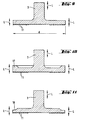
- f r stands for the radial resonance frequency c L for the longitudinal sound velocity in the tool
- D M for the average diameter of the disk-shaped tool.
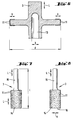
- a finger-shaped processing tool 3 for slot processing is shown. It has a stick-shaped insertion end 15 and one cylindrical body 14, on the outer surface of the cutting body 11 are arranged with undefined cutting edges. Its axial length I is matched to the introduced longitudinal vibrations of ⁇ / 2. The tool 3 oscillates laterally to the cutting direction, which facilitates flushing of the cutting area.
- a small eccentric mass of approximately 1-30 g is additionally arranged at the front end. Due to the small eccentric mass, the longitudinal vibration is converted into a bending mode. The tool vibrates in the direction of the contact pressure.
- FIG. 12 shows a cylindrical grinding tool 3 for surface processing in axial section.
- An axially extending grinding surface 19 with grinding bodies 11 with undefined cutting edges is arranged on its circumference.
- the tool has an axial bore 13 with a diameter b.
- the outer diameter of the roller-shaped tool 3 is provided with the reference symbol d.
- f r stands for the radial resonance frequency
- c L for the longitudinal speed of sound in the tool
- D M for the mean diameter of the cylindrical tool.
- the introduced longitudinal ultrasonic vibration is converted into radial waves V by transverse contractions in the tool designed in this way in the vibration node.
- the tool vibrates again in Direction of contact pressure.
- two or more such tools 3 are preferably arranged one behind the other.
- the structure of the hand-held device shown schematically in FIG. 13 largely corresponds to the device shown in FIG. 1. The difference is that the electroacoustic transducer 4 is designed to generate ultrasonic torsion waves with a wavelength ⁇ of approximately 5-20 cm.
- the tool itself is preferably equipped with PCD cutting edges or diamond segments.
- Figs. 14 and 15 In the event that both vibration support in the direction of the cutting force and in the pressing direction is desired, as shown in Figs. 14 and 15 indicated, seen in the cutting direction S, 11 recesses 12 are provided behind the cutting body.
- the cutting body 11 in Figs. 14 and 15 differ in that a cutting segment made of hard metal is indicated in FIG. 14, which extends approximately parallel to the cutting direction, while in FIG. 15 the cutting body 11 is a PCD cutting edge which is arranged inclined with respect to the cutting direction.
- the disk-shaped machining tool 3 for slot machining shown in FIG. 16 has cutting bodies 11 with undefined cutting edges on its circumference and on its outer side regions.
- the washer is tuned in the axial direction to torsional vibrations of ⁇ / 2.
- the torsional vibrations introduced result in torsional vibrations of the disk 3 in the direction of the cutting force.
- the ratio of the diameter of the shaft carrying the disk and the disk can be up to approximately 1: 4.
- FIG. 17 shows a finger-shaped grinding tool 3 for slot machining, which has a stick-shaped insertion end 15 and a cylindrical body 14.
- Cutting bodies 11 with undefined cutting edges are arranged on the peripheral surface of the body 14.
- the ultrasound torsional vibrations introduced result in a torsional vibration of the tool in the cutting direction.
- the disk 18 shows a grinding tool 3 in the form of a cup or face plate.
- the disk On its underside facing away from the insertion end, the disk is equipped with cutting bodies 11 with undefined cutting edges.
- the ultrasonic torsional vibration introduced excites the disc to torsional vibrations. The disc thus swings in the direction of the cutting force.
- FIG. 19 shows a vibration amplifier 5 designed as a suction device in axial section. It is provided with an axial bore 20, into which approximately radially extending suction channels 21 open. The mouth areas 22 of the suction channels 21 are arranged in the area of vibration nodes of the generated ultrasonic vibrations. In the illustrated embodiment, the suction channels 21 open in the area of the bearings 7 and 8 of the rotatable vibration amplifier 5. The circumferential toothing 10 provided on the vibration amplifier 5 for the transmission of the driving force from the drive unit is also indicated. In an alternative and not shown embodiment variant, the vibration amplifier 5 can be preceded by a separate suction module and preferably connected to it in a rotationally fixed manner. The design of the suction module is analogous to the vibration amplifier 5 designed as a suction device. The cuttings sucked in via the axial bore 20 are discharged in the direction of arrow E through the radial suction channels 21 to a connected vacuum cleaner.
- the vibrations of the machining tool excited by ultrasonic vibrations support the abrasive or machining removal mechanism caused by the rotation of the machining tool by means of an additional dismantling mechanism in the form of a direct impact of the machining tool in the direction of the pressing force, the cutting force or laterally.
- the superimposition of two degradation mechanisms increases the degradation rate even further.
- the contact pressure to be applied by the user of the device is reduced.
- the noise and vibration pollution of the user of the hand-held device according to the invention is reduced by the ultrasound support compared to the hammer drilling devices.
- the wear on the machining tools used in the hand-held device for example due to friction or chemical interaction between the cutting edge of the machining tool and the workpiece, is reduced.
- the heat load on the cutting edge of the tool is reduced. This increases the service life of the handheld tool combination even further.
- the safety of the handheld machine tool combinations for grinding inserts is reduced by reducing the number of revolutions required Tools increased compared to the known grinding machines.
- the hand-held device according to the invention can be used in combination with the processing tools according to the invention for the material-removing processing of brittle materials as well as for the processing of ductile-failing materials, for example soft metals such as aluminum, copper etc.
- the improvements according to the invention also make it possible to further reduce the dust load on the user which occurs during the machining of materials
Landscapes
- Engineering & Computer Science (AREA)
- Mechanical Engineering (AREA)
- Mining & Mineral Resources (AREA)
- Grinding And Polishing Of Tertiary Curved Surfaces And Surfaces With Complex Shapes (AREA)
- Drilling And Boring (AREA)
- Processing Of Stones Or Stones Resemblance Materials (AREA)
- Portable Power Tools In General (AREA)
- Finish Polishing, Edge Sharpening, And Grinding By Specific Grinding Devices (AREA)
- Cutting Tools, Boring Holders, And Turrets (AREA)
- Turning (AREA)
- Apparatuses For Generation Of Mechanical Vibrations (AREA)
Applications Claiming Priority (2)
| Application Number | Priority Date | Filing Date | Title |
|---|---|---|---|
| DE4444853A DE4444853B4 (de) | 1994-12-16 | 1994-12-16 | Handgerät zur materialabtragenden Bearbeitung mit elektroakustischem Wandler für die Erzeugung von Ultraschallschwingungen |
| DE4444853 | 1994-12-16 |
Publications (3)
| Publication Number | Publication Date |
|---|---|
| EP0720890A1 true EP0720890A1 (fr) | 1996-07-10 |
| EP0720890B1 EP0720890B1 (fr) | 1999-05-06 |
| EP0720890B2 EP0720890B2 (fr) | 2002-06-05 |
Family
ID=6535980
Family Applications (1)
| Application Number | Title | Priority Date | Filing Date |
|---|---|---|---|
| EP95810676A Expired - Lifetime EP0720890B2 (fr) | 1994-12-16 | 1995-10-30 | Outil à main pour l'usinage par enlèvement de matière pour matières fragiles et/ou non ductiles |
Country Status (7)
| Country | Link |
|---|---|
| US (1) | US5733074A (fr) |
| EP (1) | EP0720890B2 (fr) |
| JP (1) | JP3688368B2 (fr) |
| KR (1) | KR100354368B1 (fr) |
| AT (1) | ATE179645T1 (fr) |
| DE (2) | DE4444853B4 (fr) |
| ES (1) | ES2132581T5 (fr) |
Cited By (6)
| Publication number | Priority date | Publication date | Assignee | Title |
|---|---|---|---|---|
| EP1422034A1 (fr) * | 2002-11-19 | 2004-05-26 | Siemens Aktiengesellschaft | Procédé d'usinage d'une pièce |
| WO2006056316A1 (fr) * | 2004-11-24 | 2006-06-01 | Fraunhofer-Gesellschaft zur Förderung der angewandten Forschung e.V. | Dispositif porte-outil, machine-outil dotee d'un dispositif porte-outil et procede de forage notamment pour forer des trous profonds |
| DE102004061222B3 (de) * | 2004-12-20 | 2006-07-13 | Kastriot Merlaku | Schleifmaschine |
| CN106312698A (zh) * | 2016-08-31 | 2017-01-11 | 深圳天珑无线科技有限公司 | 一种抛光设备 |
| WO2018114321A1 (fr) * | 2016-12-19 | 2018-06-28 | Robert Bosch Gmbh | Perceuse à ultrasons |
| WO2018146531A1 (fr) * | 2017-02-13 | 2018-08-16 | Schott-Diamantwerkzeuge Gmbh | Perceuse à main à ultrasons |
Families Citing this family (229)
| Publication number | Priority date | Publication date | Assignee | Title |
|---|---|---|---|---|
| JPH1058290A (ja) * | 1996-08-21 | 1998-03-03 | Hiroshi Hashimoto | 硬脆材料の研削装置 |
| JP2857616B2 (ja) * | 1996-11-01 | 1999-02-17 | 株式会社コンセック | コアドリル |
| US5993300A (en) * | 1997-08-18 | 1999-11-30 | Hashimoto; Hiroshi | Ultrasonic vibration composite processing tool |
| SE517790C2 (sv) * | 1999-02-10 | 2002-07-16 | Sandvik Ab | Verktyg för spånavskiljande bearbetning |
| US6209429B1 (en) * | 1999-06-28 | 2001-04-03 | Xerox Corporation | Machining hollow cylinders |
| DE19963636C2 (de) * | 1999-12-29 | 2002-02-28 | Heraeus Quarzglas | Bohreinrichtung für spröde Werkstoffe |
| DE10025352B4 (de) * | 2000-05-23 | 2007-09-20 | Hilti Ag | Werkzeuggerät mit einem Ultraschalladapter |
| US6475065B1 (en) * | 2000-09-08 | 2002-11-05 | 3M Innovative Properties Company | Rigid polymeric cutting article, a rotary tool having the article attached thereto, and a method of using |
| US6572473B1 (en) * | 2000-10-06 | 2003-06-03 | Igt | Gaming device having game scheme allowing player skill to affect symbol movement without affecting award |
| JP2002253027A (ja) * | 2001-02-27 | 2002-09-10 | Honda Motor Co Ltd | 刈払機の駆動軸構造 |
| US11229472B2 (en) | 2001-06-12 | 2022-01-25 | Cilag Gmbh International | Modular battery powered handheld surgical instrument with multiple magnetic position sensors |
| US6786684B1 (en) | 2001-08-15 | 2004-09-07 | Robert J. Ecker | Tubular hole cutter |
| DE10162636A1 (de) * | 2001-12-20 | 2003-07-03 | Hilti Ag | Ultraschallkernbohrkrone |
| JP3680941B2 (ja) * | 2002-01-18 | 2005-08-10 | マックス株式会社 | コンクリートドリル |
| DE10249569B4 (de) * | 2002-10-24 | 2005-03-17 | Robert Bosch Gmbh | Werkzeugkopf zum Befestigen eines elektrischen Leiters auf der Kontaktfläche eines Substrates und Verfahren zum Durchführen der Befestigung |
| US7008149B1 (en) * | 2003-02-20 | 2006-03-07 | Rhoades Bernard G | Tool kit and method of using |
| US6907657B2 (en) * | 2003-08-19 | 2005-06-21 | Xerox Corporation | Apparatus for mounting a hollow work piece |
| US8182501B2 (en) | 2004-02-27 | 2012-05-22 | Ethicon Endo-Surgery, Inc. | Ultrasonic surgical shears and method for sealing a blood vessel using same |
| EP1753572A1 (fr) * | 2004-06-03 | 2007-02-21 | fischerwerke Artur Fischer GmbH & Co. KG | Procede, ancre et perforeuse permettant d'ancrer l'ancre dans une base d'ancrage |
| DE102004031600B4 (de) * | 2004-06-30 | 2006-04-20 | Hilti Ag | Werkzeug zur Bearbeitung eines mineralischen Untergrundes mit einem Ultraschall-Werkzeuggerät |
| JP5009159B2 (ja) | 2004-10-08 | 2012-08-22 | エシコン・エンド−サージェリィ・インコーポレイテッド | 超音波手術器具 |
| US20060130622A1 (en) * | 2004-12-22 | 2006-06-22 | 3M Innovative Properties Company | Circular blade and methods for using same |
| JP4856650B2 (ja) * | 2005-04-11 | 2012-01-18 | 一正 大西 | 切削もしくは研削装置 |
| JP4818670B2 (ja) * | 2005-09-21 | 2011-11-16 | 未来工業株式会社 | 発泡樹脂製断熱材用溝形成具、及び該断熱材への配管溝の形成方法 |
| US20070191713A1 (en) | 2005-10-14 | 2007-08-16 | Eichmann Stephen E | Ultrasonic device for cutting and coagulating |
| US7621930B2 (en) | 2006-01-20 | 2009-11-24 | Ethicon Endo-Surgery, Inc. | Ultrasound medical instrument having a medical ultrasonic blade |
| US7618220B2 (en) * | 2006-03-15 | 2009-11-17 | Mariam Jaber Suliman Al-Hussain | Rotary tool |
| US20080190036A1 (en) * | 2007-02-14 | 2008-08-14 | Ramsey W Gene | Acoustic driven toughened foam glass abrasive devices and a method for producing the same |
| US20080234709A1 (en) | 2007-03-22 | 2008-09-25 | Houser Kevin L | Ultrasonic surgical instrument and cartilage and bone shaping blades therefor |
| US8057498B2 (en) | 2007-11-30 | 2011-11-15 | Ethicon Endo-Surgery, Inc. | Ultrasonic surgical instrument blades |
| US8911460B2 (en) | 2007-03-22 | 2014-12-16 | Ethicon Endo-Surgery, Inc. | Ultrasonic surgical instruments |
| US8142461B2 (en) | 2007-03-22 | 2012-03-27 | Ethicon Endo-Surgery, Inc. | Surgical instruments |
| US8226675B2 (en) * | 2007-03-22 | 2012-07-24 | Ethicon Endo-Surgery, Inc. | Surgical instruments |
| US7824247B1 (en) * | 2007-06-01 | 2010-11-02 | The United States Of America As Represented By The Administrator Of The National Aeronautics And Space Administration | Portable rapid and quiet drill |
| US8348967B2 (en) * | 2007-07-27 | 2013-01-08 | Ethicon Endo-Surgery, Inc. | Ultrasonic surgical instruments |
| US8808319B2 (en) | 2007-07-27 | 2014-08-19 | Ethicon Endo-Surgery, Inc. | Surgical instruments |
| US8882791B2 (en) * | 2007-07-27 | 2014-11-11 | Ethicon Endo-Surgery, Inc. | Ultrasonic surgical instruments |
| US8523889B2 (en) | 2007-07-27 | 2013-09-03 | Ethicon Endo-Surgery, Inc. | Ultrasonic end effectors with increased active length |
| US8512365B2 (en) | 2007-07-31 | 2013-08-20 | Ethicon Endo-Surgery, Inc. | Surgical instruments |
| US9044261B2 (en) | 2007-07-31 | 2015-06-02 | Ethicon Endo-Surgery, Inc. | Temperature controlled ultrasonic surgical instruments |
| US8252012B2 (en) | 2007-07-31 | 2012-08-28 | Ethicon Endo-Surgery, Inc. | Ultrasonic surgical instrument with modulator |
| US8430898B2 (en) | 2007-07-31 | 2013-04-30 | Ethicon Endo-Surgery, Inc. | Ultrasonic surgical instruments |
| CN101883531B (zh) | 2007-10-05 | 2014-07-02 | 伊西康内外科公司 | 人体工程学外科手术器械 |
| US7740088B1 (en) | 2007-10-30 | 2010-06-22 | The United States Of America As Represented By The Administrator Of The National Aeronautics And Space Administration | Ultrasonic rotary-hammer drill |
| US7901423B2 (en) | 2007-11-30 | 2011-03-08 | Ethicon Endo-Surgery, Inc. | Folded ultrasonic end effectors with increased active length |
| US10010339B2 (en) | 2007-11-30 | 2018-07-03 | Ethicon Llc | Ultrasonic surgical blades |
| US9089360B2 (en) | 2008-08-06 | 2015-07-28 | Ethicon Endo-Surgery, Inc. | Devices and techniques for cutting and coagulating tissue |
| US8058771B2 (en) | 2008-08-06 | 2011-11-15 | Ethicon Endo-Surgery, Inc. | Ultrasonic device for cutting and coagulating with stepped output |
| DE102009027688A1 (de) * | 2009-01-05 | 2010-07-08 | Robert Bosch Gmbh | Handgehaltene Elektrowerkzeugmaschine |
| US9700339B2 (en) | 2009-05-20 | 2017-07-11 | Ethicon Endo-Surgery, Inc. | Coupling arrangements and methods for attaching tools to ultrasonic surgical instruments |
| US20100298743A1 (en) * | 2009-05-20 | 2010-11-25 | Ethicon Endo-Surgery, Inc. | Thermally-activated coupling arrangements and methods for attaching tools to ultrasonic surgical instruments |
| US8344596B2 (en) | 2009-06-24 | 2013-01-01 | Ethicon Endo-Surgery, Inc. | Transducer arrangements for ultrasonic surgical instruments |
| US9017326B2 (en) | 2009-07-15 | 2015-04-28 | Ethicon Endo-Surgery, Inc. | Impedance monitoring apparatus, system, and method for ultrasonic surgical instruments |
| US8461744B2 (en) * | 2009-07-15 | 2013-06-11 | Ethicon Endo-Surgery, Inc. | Rotating transducer mount for ultrasonic surgical instruments |
| US8663220B2 (en) | 2009-07-15 | 2014-03-04 | Ethicon Endo-Surgery, Inc. | Ultrasonic surgical instruments |
| DE102009041337B3 (de) * | 2009-09-15 | 2011-04-07 | Wezag Gmbh Werkzeugfabrik | Bohrmaschinen-Werkzeug |
| US9168054B2 (en) | 2009-10-09 | 2015-10-27 | Ethicon Endo-Surgery, Inc. | Surgical generator for ultrasonic and electrosurgical devices |
| US9060775B2 (en) | 2009-10-09 | 2015-06-23 | Ethicon Endo-Surgery, Inc. | Surgical generator for ultrasonic and electrosurgical devices |
| US10172669B2 (en) | 2009-10-09 | 2019-01-08 | Ethicon Llc | Surgical instrument comprising an energy trigger lockout |
| US11090104B2 (en) | 2009-10-09 | 2021-08-17 | Cilag Gmbh International | Surgical generator for ultrasonic and electrosurgical devices |
| USRE47996E1 (en) | 2009-10-09 | 2020-05-19 | Ethicon Llc | Surgical generator for ultrasonic and electrosurgical devices |
| US10441345B2 (en) | 2009-10-09 | 2019-10-15 | Ethicon Llc | Surgical generator for ultrasonic and electrosurgical devices |
| US8419759B2 (en) * | 2010-02-11 | 2013-04-16 | Ethicon Endo-Surgery, Inc. | Ultrasonic surgical instrument with comb-like tissue trimming device |
| US8531064B2 (en) * | 2010-02-11 | 2013-09-10 | Ethicon Endo-Surgery, Inc. | Ultrasonically powered surgical instruments with rotating cutting implement |
| US8579928B2 (en) | 2010-02-11 | 2013-11-12 | Ethicon Endo-Surgery, Inc. | Outer sheath and blade arrangements for ultrasonic surgical instruments |
| US9259234B2 (en) | 2010-02-11 | 2016-02-16 | Ethicon Endo-Surgery, Llc | Ultrasonic surgical instruments with rotatable blade and hollow sheath arrangements |
| US8323302B2 (en) * | 2010-02-11 | 2012-12-04 | Ethicon Endo-Surgery, Inc. | Methods of using ultrasonically powered surgical instruments with rotatable cutting implements |
| US8469981B2 (en) | 2010-02-11 | 2013-06-25 | Ethicon Endo-Surgery, Inc. | Rotatable cutting implement arrangements for ultrasonic surgical instruments |
| US8961547B2 (en) | 2010-02-11 | 2015-02-24 | Ethicon Endo-Surgery, Inc. | Ultrasonic surgical instruments with moving cutting implement |
| US8951272B2 (en) * | 2010-02-11 | 2015-02-10 | Ethicon Endo-Surgery, Inc. | Seal arrangements for ultrasonically powered surgical instruments |
| US8486096B2 (en) | 2010-02-11 | 2013-07-16 | Ethicon Endo-Surgery, Inc. | Dual purpose surgical instrument for cutting and coagulating tissue |
| US8382782B2 (en) * | 2010-02-11 | 2013-02-26 | Ethicon Endo-Surgery, Inc. | Ultrasonic surgical instruments with partially rotating blade and fixed pad arrangement |
| WO2011112967A1 (fr) * | 2010-03-11 | 2011-09-15 | Edison Welding Institute, Inc. | Module d'usinage ultrasonique |
| DE102010016561B4 (de) * | 2010-04-16 | 2014-02-13 | Langenstein & Schemann Gmbh | Vorrichtung und Verfahren zur Herstellung eines Lochs oder einer Vertiefung in einem Mauerwerkstein oder einem Mauerwerksteinformling sowie Verwendung eines Ultraschallbohrers |
| US8905689B2 (en) | 2010-04-29 | 2014-12-09 | Edison Welding Institute | Ultrasonic machining assembly for use with portable devices |
| GB2480498A (en) | 2010-05-21 | 2011-11-23 | Ethicon Endo Surgery Inc | Medical device comprising RF circuitry |
| US8795327B2 (en) | 2010-07-22 | 2014-08-05 | Ethicon Endo-Surgery, Inc. | Electrosurgical instrument with separate closure and cutting members |
| US9192431B2 (en) | 2010-07-23 | 2015-11-24 | Ethicon Endo-Surgery, Inc. | Electrosurgical cutting and sealing instrument |
| DE102010043143A1 (de) * | 2010-10-29 | 2012-05-03 | Robert Bosch Gmbh | Auswechselbares Werkzeug für eine Elektrowerkzeugmaschine und Elektrowerkzeugmaschine mit einem auswechselbaren Werkzeug |
| CN102476222B (zh) * | 2010-11-24 | 2014-12-10 | 南京德朔实业有限公司 | 用于振荡工具上的开孔器 |
| JP5716955B2 (ja) * | 2011-03-09 | 2015-05-13 | 埼玉県 | 切削加工装置,振動条件提示装置及びその方法 |
| US8968293B2 (en) | 2011-04-12 | 2015-03-03 | Covidien Lp | Systems and methods for calibrating power measurements in an electrosurgical generator |
| CN102198611B (zh) * | 2011-05-10 | 2013-10-23 | 北京航空航天大学 | 一种钉头保护贴片涂层超声振动套平方法及装置 |
| US9259265B2 (en) | 2011-07-22 | 2016-02-16 | Ethicon Endo-Surgery, Llc | Surgical instruments for tensioning tissue |
| DE102011052252A1 (de) * | 2011-07-28 | 2013-01-31 | Herrmann Ultraschalltechnik Gmbh & Co. Kg | Werkzeugkopf sowie Verfahren zur spanenden Bearbeitung |
| DE102011109514B4 (de) * | 2011-08-02 | 2014-11-20 | Faurecia Innenraum Systeme Gmbh | Verbundteil |
| USD700967S1 (en) | 2011-08-23 | 2014-03-11 | Covidien Ag | Handle for portable surgical device |
| USD687549S1 (en) | 2011-10-24 | 2013-08-06 | Ethicon Endo-Surgery, Inc. | Surgical instrument |
| US9314292B2 (en) | 2011-10-24 | 2016-04-19 | Ethicon Endo-Surgery, Llc | Trigger lockout mechanism |
| WO2013119545A1 (fr) | 2012-02-10 | 2013-08-15 | Ethicon-Endo Surgery, Inc. | Instrument chirurgical robotisé |
| US9237921B2 (en) | 2012-04-09 | 2016-01-19 | Ethicon Endo-Surgery, Inc. | Devices and techniques for cutting and coagulating tissue |
| US9241731B2 (en) | 2012-04-09 | 2016-01-26 | Ethicon Endo-Surgery, Inc. | Rotatable electrical connection for ultrasonic surgical instruments |
| US9226766B2 (en) | 2012-04-09 | 2016-01-05 | Ethicon Endo-Surgery, Inc. | Serial communication protocol for medical device |
| US9724118B2 (en) | 2012-04-09 | 2017-08-08 | Ethicon Endo-Surgery, Llc | Techniques for cutting and coagulating tissue for ultrasonic surgical instruments |
| US9439668B2 (en) | 2012-04-09 | 2016-09-13 | Ethicon Endo-Surgery, Llc | Switch arrangements for ultrasonic surgical instruments |
| US20140005705A1 (en) | 2012-06-29 | 2014-01-02 | Ethicon Endo-Surgery, Inc. | Surgical instruments with articulating shafts |
| US9226767B2 (en) | 2012-06-29 | 2016-01-05 | Ethicon Endo-Surgery, Inc. | Closed feedback control for electrosurgical device |
| US9326788B2 (en) | 2012-06-29 | 2016-05-03 | Ethicon Endo-Surgery, Llc | Lockout mechanism for use with robotic electrosurgical device |
| US9393037B2 (en) | 2012-06-29 | 2016-07-19 | Ethicon Endo-Surgery, Llc | Surgical instruments with articulating shafts |
| US9283045B2 (en) | 2012-06-29 | 2016-03-15 | Ethicon Endo-Surgery, Llc | Surgical instruments with fluid management system |
| US9198714B2 (en) | 2012-06-29 | 2015-12-01 | Ethicon Endo-Surgery, Inc. | Haptic feedback devices for surgical robot |
| US9820768B2 (en) | 2012-06-29 | 2017-11-21 | Ethicon Llc | Ultrasonic surgical instruments with control mechanisms |
| US9351754B2 (en) | 2012-06-29 | 2016-05-31 | Ethicon Endo-Surgery, Llc | Ultrasonic surgical instruments with distally positioned jaw assemblies |
| US20140005702A1 (en) | 2012-06-29 | 2014-01-02 | Ethicon Endo-Surgery, Inc. | Ultrasonic surgical instruments with distally positioned transducers |
| US9408622B2 (en) | 2012-06-29 | 2016-08-09 | Ethicon Endo-Surgery, Llc | Surgical instruments with articulating shafts |
| WO2014052181A1 (fr) | 2012-09-28 | 2014-04-03 | Ethicon Endo-Surgery, Inc. | Pince bipolaire multifonction |
| US9095367B2 (en) | 2012-10-22 | 2015-08-04 | Ethicon Endo-Surgery, Inc. | Flexible harmonic waveguides/blades for surgical instruments |
| US10201365B2 (en) | 2012-10-22 | 2019-02-12 | Ethicon Llc | Surgeon feedback sensing and display methods |
| US20140135804A1 (en) | 2012-11-15 | 2014-05-15 | Ethicon Endo-Surgery, Inc. | Ultrasonic and electrosurgical devices |
| US9724772B2 (en) * | 2013-02-15 | 2017-08-08 | Vera Tec, Inc. | Vibrating chain saw sharpener |
| US9561141B1 (en) | 2013-03-13 | 2017-02-07 | Greg Alvine | Orthopedic cast removal apparatus and method |
| US10226273B2 (en) | 2013-03-14 | 2019-03-12 | Ethicon Llc | Mechanical fasteners for use with surgical energy devices |
| US9241728B2 (en) | 2013-03-15 | 2016-01-26 | Ethicon Endo-Surgery, Inc. | Surgical instrument with multiple clamping mechanisms |
| US9814514B2 (en) | 2013-09-13 | 2017-11-14 | Ethicon Llc | Electrosurgical (RF) medical instruments for cutting and coagulating tissue |
| US9265926B2 (en) | 2013-11-08 | 2016-02-23 | Ethicon Endo-Surgery, Llc | Electrosurgical devices |
| GB2521229A (en) | 2013-12-16 | 2015-06-17 | Ethicon Endo Surgery Inc | Medical device |
| GB2521228A (en) | 2013-12-16 | 2015-06-17 | Ethicon Endo Surgery Inc | Medical device |
| US9795436B2 (en) | 2014-01-07 | 2017-10-24 | Ethicon Llc | Harvesting energy from a surgical generator |
| US9554854B2 (en) | 2014-03-18 | 2017-01-31 | Ethicon Endo-Surgery, Llc | Detecting short circuits in electrosurgical medical devices |
| US10463421B2 (en) | 2014-03-27 | 2019-11-05 | Ethicon Llc | Two stage trigger, clamp and cut bipolar vessel sealer |
| US10092310B2 (en) | 2014-03-27 | 2018-10-09 | Ethicon Llc | Electrosurgical devices |
| US9737355B2 (en) | 2014-03-31 | 2017-08-22 | Ethicon Llc | Controlling impedance rise in electrosurgical medical devices |
| US9913680B2 (en) | 2014-04-15 | 2018-03-13 | Ethicon Llc | Software algorithms for electrosurgical instruments |
| US10285724B2 (en) | 2014-07-31 | 2019-05-14 | Ethicon Llc | Actuation mechanisms and load adjustment assemblies for surgical instruments |
| JP2017532208A (ja) * | 2014-08-26 | 2017-11-02 | ナノ マテリアルズ インターナショナル コーポレイション | アルミニウム/ダイヤモンド切削工具 |
| JP6106248B2 (ja) * | 2014-11-07 | 2017-03-29 | 東台精機股▲ふん▼有限公司Tongtai Machine & Tool Co.,Ltd. | 高周波振動を有する工作機械と検出/フィードバック信号の制御方法 |
| US10639092B2 (en) | 2014-12-08 | 2020-05-05 | Ethicon Llc | Electrode configurations for surgical instruments |
| US10159524B2 (en) | 2014-12-22 | 2018-12-25 | Ethicon Llc | High power battery powered RF amplifier topology |
| US10245095B2 (en) | 2015-02-06 | 2019-04-02 | Ethicon Llc | Electrosurgical instrument with rotation and articulation mechanisms |
| US10342602B2 (en) | 2015-03-17 | 2019-07-09 | Ethicon Llc | Managing tissue treatment |
| US10321950B2 (en) | 2015-03-17 | 2019-06-18 | Ethicon Llc | Managing tissue treatment |
| US10595929B2 (en) | 2015-03-24 | 2020-03-24 | Ethicon Llc | Surgical instruments with firing system overload protection mechanisms |
| US10314638B2 (en) | 2015-04-07 | 2019-06-11 | Ethicon Llc | Articulating radio frequency (RF) tissue seal with articulating state sensing |
| US10034684B2 (en) | 2015-06-15 | 2018-07-31 | Ethicon Llc | Apparatus and method for dissecting and coagulating tissue |
| US11020140B2 (en) | 2015-06-17 | 2021-06-01 | Cilag Gmbh International | Ultrasonic surgical blade for use with ultrasonic surgical instruments |
| US10034704B2 (en) | 2015-06-30 | 2018-07-31 | Ethicon Llc | Surgical instrument with user adaptable algorithms |
| US10765470B2 (en) | 2015-06-30 | 2020-09-08 | Ethicon Llc | Surgical system with user adaptable techniques employing simultaneous energy modalities based on tissue parameters |
| US10357303B2 (en) | 2015-06-30 | 2019-07-23 | Ethicon Llc | Translatable outer tube for sealing using shielded lap chole dissector |
| US11051873B2 (en) | 2015-06-30 | 2021-07-06 | Cilag Gmbh International | Surgical system with user adaptable techniques employing multiple energy modalities based on tissue parameters |
| US10898256B2 (en) | 2015-06-30 | 2021-01-26 | Ethicon Llc | Surgical system with user adaptable techniques based on tissue impedance |
| US11129669B2 (en) | 2015-06-30 | 2021-09-28 | Cilag Gmbh International | Surgical system with user adaptable techniques based on tissue type |
| US10154852B2 (en) | 2015-07-01 | 2018-12-18 | Ethicon Llc | Ultrasonic surgical blade with improved cutting and coagulation features |
| US20170086909A1 (en) | 2015-09-30 | 2017-03-30 | Ethicon Endo-Surgery, Llc | Frequency agile generator for a surgical instrument |
| US10595930B2 (en) | 2015-10-16 | 2020-03-24 | Ethicon Llc | Electrode wiping surgical device |
| US10959771B2 (en) | 2015-10-16 | 2021-03-30 | Ethicon Llc | Suction and irrigation sealing grasper |
| US10179022B2 (en) | 2015-12-30 | 2019-01-15 | Ethicon Llc | Jaw position impedance limiter for electrosurgical instrument |
| US10959806B2 (en) | 2015-12-30 | 2021-03-30 | Ethicon Llc | Energized medical device with reusable handle |
| US10575892B2 (en) | 2015-12-31 | 2020-03-03 | Ethicon Llc | Adapter for electrical surgical instruments |
| US11229471B2 (en) | 2016-01-15 | 2022-01-25 | Cilag Gmbh International | Modular battery powered handheld surgical instrument with selective application of energy based on tissue characterization |
| US11134978B2 (en) | 2016-01-15 | 2021-10-05 | Cilag Gmbh International | Modular battery powered handheld surgical instrument with self-diagnosing control switches for reusable handle assembly |
| US11129670B2 (en) | 2016-01-15 | 2021-09-28 | Cilag Gmbh International | Modular battery powered handheld surgical instrument with selective application of energy based on button displacement, intensity, or local tissue characterization |
| US10716615B2 (en) | 2016-01-15 | 2020-07-21 | Ethicon Llc | Modular battery powered handheld surgical instrument with curved end effectors having asymmetric engagement between jaw and blade |
| US12193698B2 (en) | 2016-01-15 | 2025-01-14 | Cilag Gmbh International | Method for self-diagnosing operation of a control switch in a surgical instrument system |
| US10555769B2 (en) | 2016-02-22 | 2020-02-11 | Ethicon Llc | Flexible circuits for electrosurgical instrument |
| US10646269B2 (en) | 2016-04-29 | 2020-05-12 | Ethicon Llc | Non-linear jaw gap for electrosurgical instruments |
| US10485607B2 (en) | 2016-04-29 | 2019-11-26 | Ethicon Llc | Jaw structure with distal closure for electrosurgical instruments |
| US10987156B2 (en) | 2016-04-29 | 2021-04-27 | Ethicon Llc | Electrosurgical instrument with electrically conductive gap setting member and electrically insulative tissue engaging members |
| US10702329B2 (en) | 2016-04-29 | 2020-07-07 | Ethicon Llc | Jaw structure with distal post for electrosurgical instruments |
| US10856934B2 (en) | 2016-04-29 | 2020-12-08 | Ethicon Llc | Electrosurgical instrument with electrically conductive gap setting and tissue engaging members |
| US10456193B2 (en) | 2016-05-03 | 2019-10-29 | Ethicon Llc | Medical device with a bilateral jaw configuration for nerve stimulation |
| DE102016211740B4 (de) | 2016-06-29 | 2018-01-11 | Robert Bosch Gmbh | Verfahren und Vorrichtung zum Ultraschallbohren |
| DE102016211729A1 (de) | 2016-06-29 | 2018-01-04 | Robert Bosch Gmbh | Verfahren zum Betrieb einer Ultraschallbohrmaschine |
| DE102016211733A1 (de) * | 2016-06-29 | 2018-01-04 | Robert Bosch Gmbh | Tragbare Ultraschallbohrmaschine |
| US10245064B2 (en) | 2016-07-12 | 2019-04-02 | Ethicon Llc | Ultrasonic surgical instrument with piezoelectric central lumen transducer |
| US10893883B2 (en) | 2016-07-13 | 2021-01-19 | Ethicon Llc | Ultrasonic assembly for use with ultrasonic surgical instruments |
| US10842522B2 (en) | 2016-07-15 | 2020-11-24 | Ethicon Llc | Ultrasonic surgical instruments having offset blades |
| DE102016214498A1 (de) * | 2016-08-05 | 2018-02-08 | Schaeffler Technologies AG & Co. KG | Werkzeughalteeinrichtung und Verfahren zum Bohren |
| US10376305B2 (en) | 2016-08-05 | 2019-08-13 | Ethicon Llc | Methods and systems for advanced harmonic energy |
| US10285723B2 (en) | 2016-08-09 | 2019-05-14 | Ethicon Llc | Ultrasonic surgical blade with improved heel portion |
| USD847990S1 (en) | 2016-08-16 | 2019-05-07 | Ethicon Llc | Surgical instrument |
| US10952759B2 (en) | 2016-08-25 | 2021-03-23 | Ethicon Llc | Tissue loading of a surgical instrument |
| US10828056B2 (en) | 2016-08-25 | 2020-11-10 | Ethicon Llc | Ultrasonic transducer to waveguide acoustic coupling, connections, and configurations |
| US10532412B2 (en) | 2016-09-23 | 2020-01-14 | Milwaukee Electric Tool Corporation | Hole saw arbor assembly |
| US10751117B2 (en) | 2016-09-23 | 2020-08-25 | Ethicon Llc | Electrosurgical instrument with fluid diverter |
| US10603064B2 (en) | 2016-11-28 | 2020-03-31 | Ethicon Llc | Ultrasonic transducer |
| US11266430B2 (en) | 2016-11-29 | 2022-03-08 | Cilag Gmbh International | End effector control and calibration |
| EP3725441B1 (fr) * | 2017-01-06 | 2025-04-09 | Milwaukee Electric Tool Corporation | Scie-cloche |
| US11033325B2 (en) | 2017-02-16 | 2021-06-15 | Cilag Gmbh International | Electrosurgical instrument with telescoping suction port and debris cleaner |
| CN106825679B (zh) * | 2017-02-28 | 2018-08-21 | 西北工业大学 | 一种基于旋转式无线电能传输的超声振动气钻 |
| US10799284B2 (en) | 2017-03-15 | 2020-10-13 | Ethicon Llc | Electrosurgical instrument with textured jaws |
| US11497546B2 (en) | 2017-03-31 | 2022-11-15 | Cilag Gmbh International | Area ratios of patterned coatings on RF electrodes to reduce sticking |
| US10323426B1 (en) * | 2017-04-06 | 2019-06-18 | Kent Sandvig | Wall repair plug system |
| US10603117B2 (en) | 2017-06-28 | 2020-03-31 | Ethicon Llc | Articulation state detection mechanisms |
| US10820920B2 (en) | 2017-07-05 | 2020-11-03 | Ethicon Llc | Reusable ultrasonic medical devices and methods of their use |
| AU2018312343A1 (en) | 2017-07-31 | 2020-02-13 | Milwaukee Electric Tool Corporation | Rotary power tool |
| USD973733S1 (en) | 2017-08-15 | 2022-12-27 | Milwaukee Electric Tool Corporation | Hole saw |
| US10391609B1 (en) * | 2017-09-05 | 2019-08-27 | Optipro Systems, LLC | Modular contact assembly for rotating machine tool |
| US11484358B2 (en) | 2017-09-29 | 2022-11-01 | Cilag Gmbh International | Flexible electrosurgical instrument |
| US11490951B2 (en) | 2017-09-29 | 2022-11-08 | Cilag Gmbh International | Saline contact with electrodes |
| US11033323B2 (en) | 2017-09-29 | 2021-06-15 | Cilag Gmbh International | Systems and methods for managing fluid and suction in electrosurgical systems |
| EP4257311A3 (fr) | 2017-11-27 | 2023-12-27 | Dynatech Systems, Inc. | Systeme de fraisage sans tambour pour l'enlevement de matiere et procede de fabrication d'un systeme de fraisage sans tambour pour l'enlevement de matiere |
| CN108097995A (zh) * | 2018-02-07 | 2018-06-01 | 陕西超克能机电科技发展有限公司 | 一种手持式超声钻 |
| CN109176165A (zh) * | 2018-09-29 | 2019-01-11 | 广州汇专工具有限公司 | 超声波刀具加工装置 |
| US12262937B2 (en) | 2019-12-30 | 2025-04-01 | Cilag Gmbh International | User interface for surgical instrument with combination energy modality end-effector |
| US20210196357A1 (en) | 2019-12-30 | 2021-07-01 | Ethicon Llc | Electrosurgical instrument with asynchronous energizing electrodes |
| US11707318B2 (en) | 2019-12-30 | 2023-07-25 | Cilag Gmbh International | Surgical instrument with jaw alignment features |
| US12053224B2 (en) | 2019-12-30 | 2024-08-06 | Cilag Gmbh International | Variation in electrode parameters and deflectable electrode to modify energy density and tissue interaction |
| US20210196361A1 (en) | 2019-12-30 | 2021-07-01 | Ethicon Llc | Electrosurgical instrument with monopolar and bipolar energy capabilities |
| US12023086B2 (en) | 2019-12-30 | 2024-07-02 | Cilag Gmbh International | Electrosurgical instrument for delivering blended energy modalities to tissue |
| US11779329B2 (en) | 2019-12-30 | 2023-10-10 | Cilag Gmbh International | Surgical instrument comprising a flex circuit including a sensor system |
| US12076006B2 (en) | 2019-12-30 | 2024-09-03 | Cilag Gmbh International | Surgical instrument comprising an orientation detection system |
| US11696776B2 (en) | 2019-12-30 | 2023-07-11 | Cilag Gmbh International | Articulatable surgical instrument |
| US11986234B2 (en) | 2019-12-30 | 2024-05-21 | Cilag Gmbh International | Surgical system communication pathways |
| US12064109B2 (en) | 2019-12-30 | 2024-08-20 | Cilag Gmbh International | Surgical instrument comprising a feedback control circuit |
| US12114912B2 (en) | 2019-12-30 | 2024-10-15 | Cilag Gmbh International | Non-biased deflectable electrode to minimize contact between ultrasonic blade and electrode |
| US11950797B2 (en) | 2019-12-30 | 2024-04-09 | Cilag Gmbh International | Deflectable electrode with higher distal bias relative to proximal bias |
| US11812957B2 (en) | 2019-12-30 | 2023-11-14 | Cilag Gmbh International | Surgical instrument comprising a signal interference resolution system |
| US11786291B2 (en) | 2019-12-30 | 2023-10-17 | Cilag Gmbh International | Deflectable support of RF energy electrode with respect to opposing ultrasonic blade |
| US11779387B2 (en) | 2019-12-30 | 2023-10-10 | Cilag Gmbh International | Clamp arm jaw to minimize tissue sticking and improve tissue control |
| US12336747B2 (en) | 2019-12-30 | 2025-06-24 | Cilag Gmbh International | Method of operating a combination ultrasonic / bipolar RF surgical device with a combination energy modality end-effector |
| US11937863B2 (en) | 2019-12-30 | 2024-03-26 | Cilag Gmbh International | Deflectable electrode with variable compression bias along the length of the deflectable electrode |
| US11660089B2 (en) | 2019-12-30 | 2023-05-30 | Cilag Gmbh International | Surgical instrument comprising a sensing system |
| US11911063B2 (en) | 2019-12-30 | 2024-02-27 | Cilag Gmbh International | Techniques for detecting ultrasonic blade to electrode contact and reducing power to ultrasonic blade |
| US12349961B2 (en) | 2019-12-30 | 2025-07-08 | Cilag Gmbh International | Electrosurgical instrument with electrodes operable in bipolar and monopolar modes |
| US11452525B2 (en) | 2019-12-30 | 2022-09-27 | Cilag Gmbh International | Surgical instrument comprising an adjustment system |
| US11986201B2 (en) | 2019-12-30 | 2024-05-21 | Cilag Gmbh International | Method for operating a surgical instrument |
| US11944366B2 (en) | 2019-12-30 | 2024-04-02 | Cilag Gmbh International | Asymmetric segmented ultrasonic support pad for cooperative engagement with a movable RF electrode |
| US12343063B2 (en) | 2019-12-30 | 2025-07-01 | Cilag Gmbh International | Multi-layer clamp arm pad for enhanced versatility and performance of a surgical device |
| US12082808B2 (en) | 2019-12-30 | 2024-09-10 | Cilag Gmbh International | Surgical instrument comprising a control system responsive to software configurations |
| USD940767S1 (en) | 2020-01-24 | 2022-01-11 | Dynatech Systems, Inc. | Cutter head for grinding machines and the like |
| CN111390660B (zh) * | 2020-05-08 | 2021-10-22 | 太原理工大学 | 整体叶轮类零件超声等静压粘弹磨料抛光装置及抛光方法 |
| US12471982B2 (en) | 2020-12-02 | 2025-11-18 | Cilag Gmbh International | Method for tissue treatment by surgical instrument |
| EP4082703A1 (fr) * | 2021-04-26 | 2022-11-02 | Hilti Aktiengesellschaft | Carotteuse et procédé de libération d'une carotte d'une couronne de forage |
| EP4082721A1 (fr) | 2021-04-26 | 2022-11-02 | Hilti Aktiengesellschaft | Procédé d'activation et de désactivation d'un verrouillage de broche dans une machine-outil et machine-outil |
| US11957342B2 (en) | 2021-11-01 | 2024-04-16 | Cilag Gmbh International | Devices, systems, and methods for detecting tissue and foreign objects during a surgical operation |
| US12508021B2 (en) | 2021-11-01 | 2025-12-30 | Cilag Gmbh International | Devices, systems, and methods for detecting tissue and foreign objects during a surgical operation |
| JP7107512B1 (ja) * | 2021-11-17 | 2022-07-27 | 株式会社ジーベックテクノロジー | 軸付き砥石および研磨工具 |
| SE546148C2 (en) * | 2022-04-21 | 2024-06-11 | Husqvarna Ab | Electric power cutter with a vibration function |
| CN116623114B (zh) * | 2023-07-24 | 2023-10-17 | 内蒙古工业大学 | 一种金属板表面超声振动强化处理的装置 |
Citations (8)
| Publication number | Priority date | Publication date | Assignee | Title |
|---|---|---|---|---|
| US2818686A (en) * | 1956-02-28 | 1958-01-07 | Gulton Ind Inc | Rotating ultrasonic drill |
| US3471724A (en) * | 1965-04-08 | 1969-10-07 | Cavitron Corp | Magnetostrictive vibrator for high frequency machining of hard materials |
| US3614484A (en) * | 1970-03-25 | 1971-10-19 | Branson Instr | Ultrasonic motion adapter for a machine tool |
| US4667755A (en) * | 1984-02-29 | 1987-05-26 | Hawera Probst Gmbh & Co. | Drill bit having hollow cylindrical body and a plurality of PCD cutting elements |
| EP0277823A1 (fr) * | 1987-02-04 | 1988-08-10 | Taga Electric Co. Ltd. | Dispositif de coupe à ultrasons |
| US4828052A (en) * | 1988-06-20 | 1989-05-09 | The United States Of America As Represented By The United States Department Of Energy | Ultrasonic drilling apparatus |
| CH676097A5 (en) * | 1988-10-27 | 1990-12-14 | Maho Hansen Ag | Ultrasonic machine - has tube supplying flushing liquid protruding into axial bore through rotary tool |
| DE3919895A1 (de) * | 1989-06-19 | 1990-12-20 | Kadia Diamant | Hochfrequenzhonen |
Family Cites Families (14)
| Publication number | Priority date | Publication date | Assignee | Title |
|---|---|---|---|---|
| CA900752A (en) * | 1972-05-23 | E. Bullen James | Machine tool | |
| US2792674A (en) * | 1954-03-19 | 1957-05-21 | Cavitron Corp | Vibratory machine tool |
| GB1143785A (fr) * | 1966-03-16 | |||
| US3754448A (en) * | 1971-06-08 | 1973-08-28 | Univ Ohio State | Sonic energy metal working process |
| SU437537A1 (ru) * | 1972-08-11 | 1974-07-30 | Одесский Завод Фрезерных Станков Им. С.М.Кирова | Ультразвукова головка |
| JPS5973272A (ja) * | 1982-10-18 | 1984-04-25 | Inoue Japax Res Inc | 数値制御研磨装置 |
| JPS59182008A (ja) * | 1983-03-28 | 1984-10-16 | Matsushita Electric Works Ltd | 振動ドリル |
| FR2613651B1 (fr) * | 1987-04-10 | 1994-07-22 | Onera (Off Nat Aerospatiale) | Machine d'usinage par abrasion ultrasonore |
| US5009553A (en) * | 1987-07-20 | 1991-04-23 | Nowman William G | Method and apparatus for drilling hardplate |
| DE8805832U1 (de) * | 1988-05-03 | 1988-07-07 | Mafell-Ultrasonics GmbH Keramik-Erosion, 7238 Oberndorf | Vorrichtung zur Bearbeitung von sehr hartem Werkstoff mittels eines Bearbeitungswerkzeugs |
| GB8810976D0 (en) * | 1988-05-10 | 1988-06-15 | Sra Dev Ltd | Cutting brittle materials |
| DE8814468U1 (de) * | 1988-11-19 | 1989-01-12 | Dieter Hansen AG, Wattwil | Ultraschallbearbeitungswerkzeug |
| DE4210928C2 (de) * | 1992-04-02 | 1994-04-28 | Kopp Verfahrenstech Gmbh | Ultraschallerregtes Honwerkzeug und Verfahren zu seiner Nachjustierung |
| US5361543A (en) * | 1992-10-01 | 1994-11-08 | Michael Bory | Device for ultrasonic erosion of a workpiece |
-
1994
- 1994-12-16 DE DE4444853A patent/DE4444853B4/de not_active Expired - Lifetime
-
1995
- 1995-10-30 DE DE59505839T patent/DE59505839D1/de not_active Expired - Lifetime
- 1995-10-30 EP EP95810676A patent/EP0720890B2/fr not_active Expired - Lifetime
- 1995-10-30 AT AT95810676T patent/ATE179645T1/de active
- 1995-10-30 ES ES95810676T patent/ES2132581T5/es not_active Expired - Lifetime
- 1995-12-04 KR KR1019950046360A patent/KR100354368B1/ko not_active Expired - Lifetime
- 1995-12-15 US US08/572,771 patent/US5733074A/en not_active Expired - Lifetime
- 1995-12-18 JP JP32908895A patent/JP3688368B2/ja not_active Expired - Lifetime
Patent Citations (8)
| Publication number | Priority date | Publication date | Assignee | Title |
|---|---|---|---|---|
| US2818686A (en) * | 1956-02-28 | 1958-01-07 | Gulton Ind Inc | Rotating ultrasonic drill |
| US3471724A (en) * | 1965-04-08 | 1969-10-07 | Cavitron Corp | Magnetostrictive vibrator for high frequency machining of hard materials |
| US3614484A (en) * | 1970-03-25 | 1971-10-19 | Branson Instr | Ultrasonic motion adapter for a machine tool |
| US4667755A (en) * | 1984-02-29 | 1987-05-26 | Hawera Probst Gmbh & Co. | Drill bit having hollow cylindrical body and a plurality of PCD cutting elements |
| EP0277823A1 (fr) * | 1987-02-04 | 1988-08-10 | Taga Electric Co. Ltd. | Dispositif de coupe à ultrasons |
| US4828052A (en) * | 1988-06-20 | 1989-05-09 | The United States Of America As Represented By The United States Department Of Energy | Ultrasonic drilling apparatus |
| CH676097A5 (en) * | 1988-10-27 | 1990-12-14 | Maho Hansen Ag | Ultrasonic machine - has tube supplying flushing liquid protruding into axial bore through rotary tool |
| DE3919895A1 (de) * | 1989-06-19 | 1990-12-20 | Kadia Diamant | Hochfrequenzhonen |
Cited By (6)
| Publication number | Priority date | Publication date | Assignee | Title |
|---|---|---|---|---|
| EP1422034A1 (fr) * | 2002-11-19 | 2004-05-26 | Siemens Aktiengesellschaft | Procédé d'usinage d'une pièce |
| WO2006056316A1 (fr) * | 2004-11-24 | 2006-06-01 | Fraunhofer-Gesellschaft zur Förderung der angewandten Forschung e.V. | Dispositif porte-outil, machine-outil dotee d'un dispositif porte-outil et procede de forage notamment pour forer des trous profonds |
| DE102004061222B3 (de) * | 2004-12-20 | 2006-07-13 | Kastriot Merlaku | Schleifmaschine |
| CN106312698A (zh) * | 2016-08-31 | 2017-01-11 | 深圳天珑无线科技有限公司 | 一种抛光设备 |
| WO2018114321A1 (fr) * | 2016-12-19 | 2018-06-28 | Robert Bosch Gmbh | Perceuse à ultrasons |
| WO2018146531A1 (fr) * | 2017-02-13 | 2018-08-16 | Schott-Diamantwerkzeuge Gmbh | Perceuse à main à ultrasons |
Also Published As
| Publication number | Publication date |
|---|---|
| DE4444853A1 (de) | 1996-06-20 |
| DE4444853B4 (de) | 2006-09-28 |
| JPH08243952A (ja) | 1996-09-24 |
| ES2132581T3 (es) | 1999-08-16 |
| ES2132581T5 (es) | 2002-11-16 |
| KR100354368B1 (ko) | 2002-12-11 |
| EP0720890B1 (fr) | 1999-05-06 |
| ATE179645T1 (de) | 1999-05-15 |
| DE59505839D1 (de) | 1999-06-10 |
| EP0720890B2 (fr) | 2002-06-05 |
| US5733074A (en) | 1998-03-31 |
| KR960021402A (ko) | 1996-07-18 |
| JP3688368B2 (ja) | 2005-08-24 |
Similar Documents
| Publication | Publication Date | Title |
|---|---|---|
| EP0720890B1 (fr) | Outil à main pour l'usinage par enlèvement de matière pour matières fragiles et/ou non ductiles | |
| EP1669148B1 (fr) | Ensemble porte-outils d'usinage rotatif assisté par ultra-sons | |
| EP1323496B1 (fr) | Trépan de forage pour perçage à ultra-sons | |
| EP2170518B1 (fr) | Broyeur vibrant de laboratoire avec godets de broyage inclinés | |
| EP2383072A1 (fr) | Outil de forage | |
| EP0316272B1 (fr) | Elément de fixation pour l'enforcement dans des matériaux durs | |
| EP0733443A1 (fr) | Dispositif pour transmettre des coups par impulsion sur un outil à rotation continue | |
| EP3951057A1 (fr) | Système de rouleau de traitement du sol pour une machine de traitement du sol | |
| DE3713544A1 (de) | Angetriebener erdbohrer und verfahren zum erdbohren | |
| DE3046190A1 (de) | Fraeswerkzeug zum herstellen von ausnehmungen in bauteilen aus mauerwerk, beton oder anderen sproeden materialien | |
| EP0846835A2 (fr) | Trépan de forage du béton ou de la roche avec rainures d'évacuation hélicoidales | |
| DE202017100736U1 (de) | Ultraschall-Handbohrmaschine | |
| EP1716980A1 (fr) | Outil portatif avec entraînement à basculement | |
| EP1602428A1 (fr) | Outil électrique actionné à la main | |
| DE4341378A1 (de) | Bohrvorrichtung mit radial auslenkbarer Bohrspindel | |
| DE2735368A1 (de) | Gesteinsbohrer mit hartmetall- bohrkopf | |
| EP1358965A2 (fr) | Dispositif d'entraínement pour arbre oscillant | |
| EP1612018B1 (fr) | Outil pour travailler des matériaux minéraux | |
| DE60200115T2 (de) | Bearbeitungsverfahren für schwer zu bearbeitende Materialien und Bearbeitungswerkzeug dafür | |
| EP1535704B1 (fr) | Porte-outil pour un outil rotatif à percussion | |
| DE3301671C2 (fr) | ||
| EP1618999A1 (fr) | marteau perforateur et/ou marteau-burineur | |
| DE2821248C3 (de) | Gesteinsbohrkrone zum Drehschlagbohrer | |
| DE10232314A1 (de) | Vorrichtung und Verfahren zum Verdichten von Böden und zur Herstellung von säulenförmigen Körpern im Boden mit Hilfe von Tiefenrüttlern | |
| EP1602839A1 (fr) | Chevillez pour insérer dans un forage |
Legal Events
| Date | Code | Title | Description |
|---|---|---|---|
| PUAI | Public reference made under article 153(3) epc to a published international application that has entered the european phase |
Free format text: ORIGINAL CODE: 0009012 |
|
| AK | Designated contracting states |
Kind code of ref document: A1 Designated state(s): AT BE CH DE ES FR GB IT LI SE |
|
| 17P | Request for examination filed |
Effective date: 19960723 |
|
| 17Q | First examination report despatched |
Effective date: 19980508 |
|
| GRAG | Despatch of communication of intention to grant |
Free format text: ORIGINAL CODE: EPIDOS AGRA |
|
| GRAG | Despatch of communication of intention to grant |
Free format text: ORIGINAL CODE: EPIDOS AGRA |
|
| GRAH | Despatch of communication of intention to grant a patent |
Free format text: ORIGINAL CODE: EPIDOS IGRA |
|
| GRAH | Despatch of communication of intention to grant a patent |
Free format text: ORIGINAL CODE: EPIDOS IGRA |
|
| GRAA | (expected) grant |
Free format text: ORIGINAL CODE: 0009210 |
|
| ITF | It: translation for a ep patent filed | ||
| AK | Designated contracting states |
Kind code of ref document: B1 Designated state(s): AT BE CH DE ES FR GB IT LI SE |
|
| REF | Corresponds to: |
Ref document number: 179645 Country of ref document: AT Date of ref document: 19990515 Kind code of ref document: T |
|
| REG | Reference to a national code |
Ref country code: CH Ref legal event code: EP |
|
| REF | Corresponds to: |
Ref document number: 59505839 Country of ref document: DE Date of ref document: 19990610 |
|
| ET | Fr: translation filed | ||
| REG | Reference to a national code |
Ref country code: ES Ref legal event code: FG2A Ref document number: 2132581 Country of ref document: ES Kind code of ref document: T3 |
|
| GBT | Gb: translation of ep patent filed (gb section 77(6)(a)/1977) |
Effective date: 19990726 |
|
| PLBI | Opposition filed |
Free format text: ORIGINAL CODE: 0009260 |
|
| PLBF | Reply of patent proprietor to notice(s) of opposition |
Free format text: ORIGINAL CODE: EPIDOS OBSO |
|
| 26 | Opposition filed |
Opponent name: ROBERT BOSCH GMBH Effective date: 20000207 |
|
| PLBF | Reply of patent proprietor to notice(s) of opposition |
Free format text: ORIGINAL CODE: EPIDOS OBSO |
|
| PLBF | Reply of patent proprietor to notice(s) of opposition |
Free format text: ORIGINAL CODE: EPIDOS OBSO |
|
| REG | Reference to a national code |
Ref country code: GB Ref legal event code: IF02 |
|
| PLAW | Interlocutory decision in opposition |
Free format text: ORIGINAL CODE: EPIDOS IDOP |
|
| PLAW | Interlocutory decision in opposition |
Free format text: ORIGINAL CODE: EPIDOS IDOP |
|
| GRAH | Despatch of communication of intention to grant a patent |
Free format text: ORIGINAL CODE: EPIDOS IGRA |
|
| PUAH | Patent maintained in amended form |
Free format text: ORIGINAL CODE: 0009272 |
|
| STAA | Information on the status of an ep patent application or granted ep patent |
Free format text: STATUS: PATENT MAINTAINED AS AMENDED |
|
| 27A | Patent maintained in amended form |
Effective date: 20020605 |
|
| AK | Designated contracting states |
Kind code of ref document: B2 Designated state(s): AT BE CH DE ES FR GB IT LI SE |
|
| REG | Reference to a national code |
Ref country code: CH Ref legal event code: AEN Free format text: AUFRECHTERHALTUNG DES PATENTES IN GEAENDERTER FORM |
|
| GBTA | Gb: translation of amended ep patent filed (gb section 77(6)(b)/1977) | ||
| ET3 | Fr: translation filed ** decision concerning opposition | ||
| REG | Reference to a national code |
Ref country code: ES Ref legal event code: DC2A Kind code of ref document: T5 Effective date: 20020619 |
|
| PGFP | Annual fee paid to national office [announced via postgrant information from national office to epo] |
Ref country code: AT Payment date: 20101014 Year of fee payment: 16 |
|
| PGFP | Annual fee paid to national office [announced via postgrant information from national office to epo] |
Ref country code: IT Payment date: 20101022 Year of fee payment: 16 |
|
| PGFP | Annual fee paid to national office [announced via postgrant information from national office to epo] |
Ref country code: ES Payment date: 20111115 Year of fee payment: 17 Ref country code: SE Payment date: 20111011 Year of fee payment: 17 Ref country code: CH Payment date: 20111012 Year of fee payment: 17 |
|
| REG | Reference to a national code |
Ref country code: CH Ref legal event code: PL |
|
| REG | Reference to a national code |
Ref country code: AT Ref legal event code: MM01 Ref document number: 179645 Country of ref document: AT Kind code of ref document: T Effective date: 20121030 |
|
| PG25 | Lapsed in a contracting state [announced via postgrant information from national office to epo] |
Ref country code: LI Free format text: LAPSE BECAUSE OF NON-PAYMENT OF DUE FEES Effective date: 20121031 Ref country code: SE Free format text: LAPSE BECAUSE OF NON-PAYMENT OF DUE FEES Effective date: 20121031 Ref country code: CH Free format text: LAPSE BECAUSE OF NON-PAYMENT OF DUE FEES Effective date: 20121031 Ref country code: AT Free format text: LAPSE BECAUSE OF NON-PAYMENT OF DUE FEES Effective date: 20121030 |
|
| PG25 | Lapsed in a contracting state [announced via postgrant information from national office to epo] |
Ref country code: IT Free format text: LAPSE BECAUSE OF NON-PAYMENT OF DUE FEES Effective date: 20121030 |
|
| REG | Reference to a national code |
Ref country code: ES Ref legal event code: FD2A Effective date: 20140115 |
|
| PG25 | Lapsed in a contracting state [announced via postgrant information from national office to epo] |
Ref country code: ES Free format text: LAPSE BECAUSE OF NON-PAYMENT OF DUE FEES Effective date: 20121031 |
|
| PGFP | Annual fee paid to national office [announced via postgrant information from national office to epo] |
Ref country code: FR Payment date: 20141008 Year of fee payment: 20 Ref country code: GB Payment date: 20141029 Year of fee payment: 20 Ref country code: DE Payment date: 20141023 Year of fee payment: 20 |
|
| PGFP | Annual fee paid to national office [announced via postgrant information from national office to epo] |
Ref country code: BE Payment date: 20141013 Year of fee payment: 20 |
|
| REG | Reference to a national code |
Ref country code: DE Ref legal event code: R071 Ref document number: 59505839 Country of ref document: DE |
|
| REG | Reference to a national code |
Ref country code: GB Ref legal event code: PE20 Expiry date: 20151029 |
|
| PG25 | Lapsed in a contracting state [announced via postgrant information from national office to epo] |
Ref country code: GB Free format text: LAPSE BECAUSE OF EXPIRATION OF PROTECTION Effective date: 20151029 |