EP0721865A2 - Module cylindrique de sac gonflable - Google Patents
Module cylindrique de sac gonflable Download PDFInfo
- Publication number
- EP0721865A2 EP0721865A2 EP96300164A EP96300164A EP0721865A2 EP 0721865 A2 EP0721865 A2 EP 0721865A2 EP 96300164 A EP96300164 A EP 96300164A EP 96300164 A EP96300164 A EP 96300164A EP 0721865 A2 EP0721865 A2 EP 0721865A2
- Authority
- EP
- European Patent Office
- Prior art keywords
- air bag
- housing
- module assembly
- tubular member
- inflator device
- Prior art date
- Legal status (The legal status is an assumption and is not a legal conclusion. Google has not performed a legal analysis and makes no representation as to the accuracy of the status listed.)
- Granted
Links
- 239000000463 material Substances 0.000 claims description 11
- 230000000452 restraining effect Effects 0.000 claims description 3
- 230000004888 barrier function Effects 0.000 claims description 2
- 239000007789 gas Substances 0.000 description 30
- 230000000712 assembly Effects 0.000 description 11
- 238000000429 assembly Methods 0.000 description 11
- 238000009434 installation Methods 0.000 description 11
- 230000000694 effects Effects 0.000 description 5
- 230000001681 protective effect Effects 0.000 description 5
- 238000004519 manufacturing process Methods 0.000 description 4
- 229910000831 Steel Inorganic materials 0.000 description 3
- 239000000446 fuel Substances 0.000 description 3
- 239000010959 steel Substances 0.000 description 3
- IJGRMHOSHXDMSA-UHFFFAOYSA-N Atomic nitrogen Chemical compound N#N IJGRMHOSHXDMSA-UHFFFAOYSA-N 0.000 description 2
- 239000004820 Pressure-sensitive adhesive Substances 0.000 description 2
- NIXOWILDQLNWCW-UHFFFAOYSA-N acrylic acid group Chemical group C(C=C)(=O)O NIXOWILDQLNWCW-UHFFFAOYSA-N 0.000 description 2
- 239000000853 adhesive Substances 0.000 description 2
- 230000001070 adhesive effect Effects 0.000 description 2
- 238000002485 combustion reaction Methods 0.000 description 2
- -1 e.g. Substances 0.000 description 2
- 239000007788 liquid Substances 0.000 description 2
- 239000002184 metal Substances 0.000 description 2
- 230000000717 retained effect Effects 0.000 description 2
- 229910000851 Alloy steel Inorganic materials 0.000 description 1
- 229910000975 Carbon steel Inorganic materials 0.000 description 1
- 239000010962 carbon steel Substances 0.000 description 1
- 239000000919 ceramic Substances 0.000 description 1
- 238000002788 crimping Methods 0.000 description 1
- 238000006073 displacement reaction Methods 0.000 description 1
- 238000001914 filtration Methods 0.000 description 1
- 230000003116 impacting effect Effects 0.000 description 1
- 238000010348 incorporation Methods 0.000 description 1
- 238000007373 indentation Methods 0.000 description 1
- 239000011261 inert gas Substances 0.000 description 1
- 238000003780 insertion Methods 0.000 description 1
- 230000037431 insertion Effects 0.000 description 1
- 238000000034 method Methods 0.000 description 1
- 229910052757 nitrogen Inorganic materials 0.000 description 1
- 238000003860 storage Methods 0.000 description 1
- 230000001960 triggered effect Effects 0.000 description 1
- 210000002268 wool Anatomy 0.000 description 1
Images


Classifications
-
- B—PERFORMING OPERATIONS; TRANSPORTING
- B60—VEHICLES IN GENERAL
- B60R—VEHICLES, VEHICLE FITTINGS, OR VEHICLE PARTS, NOT OTHERWISE PROVIDED FOR
- B60R21/00—Arrangements or fittings on vehicles for protecting or preventing injuries to occupants or pedestrians in case of accidents or other traffic risks
- B60R21/02—Occupant safety arrangements or fittings, e.g. crash pads
- B60R21/16—Inflatable occupant restraints or confinements designed to inflate upon impact or impending impact, e.g. air bags
- B60R21/20—Arrangements for storing inflatable members in their non-use or deflated condition; Arrangement or mounting of air bag modules or components
- B60R21/203—Arrangements for storing inflatable members in their non-use or deflated condition; Arrangement or mounting of air bag modules or components in steering wheels or steering columns
- B60R21/2032—Arrangements for storing inflatable members in their non-use or deflated condition; Arrangement or mounting of air bag modules or components in steering wheels or steering columns the inflator or inflatable member not being rotatable with the steering wheel; Arrangements using the steering column or steering wheel rim for storing, supplying or evacuating the inflation gas or for storing the inflatable member
Definitions
- This invention relates generally to systems for the passive restraint of motor vehicle occupants and, more particularly, to module housings and assemblies used therein.
- a cushion or bag that is inflated with gas, e.g., an "air bag", when the vehicle encounters sudden deceleration, such as in a collision.
- gas e.g., an "air bag”
- the rapidly evolving gas with which the bag is typically filled is an inert gas, e.g., nitrogen.
- the air bag is normally housed in an uninflated and folded condition to minimize space requirements.
- gas is discharged from an inflator to rapidly inflate the air bag.
- the air bag upon inflation, serves to restrain the movement of the vehicle occupant as the collision proceeds.
- such air bags are commonly designed to be inflated in no more than a few milliseconds.
- Vehicular inflatable restraint systems generally include multiple crash sensors generally positioned about or mounted to the frame and/or body of the subject vehicle and serve to sense sudden decelerations by the vehicle. In turn, the sensor sends a signal to an air bag module or assembly strategically positioned within the riding compartment of the vehicle to actuate deployment of the air bag.
- an air bag provided for the protection of a vehicle driver i.e., a driver side air bag
- a driver side air bag is mounted in a storage compartment located along the steering column of the vehicle.
- the air bag is housed outside the plane of the steering wheel, resulting in the hub of the steering wheel assembly being larger than otherwise needed as well as in the displacement of items such as horn switches and cruise controls that otherwise may have more easily and/or desirably been centrally located at the steering wheel hub.
- driver side air bags are generally circular, oval or elliptical in shape, largely as a result of the practical limitations in the folding of air bags, such driver side air bag installations are commonly covered with a rectangularly shaped cover. Thus, rather exact and complex folding of the air bag is generally required to better ensure proper deployment of the air bag from such an assembly.
- a general object of the invention is to provide an improved air bag module assembly and combinations therewith.
- a more specific objective of the invention is to overcome one or more of the problems described above and/or satisfy, at least in part, one or more of the needs described above.
- the general object of the invention can be attained, at least in part, through a cylindrical air bag module assembly that includes a module housing, an inflator device, and an inflatable air bag.
- the module housing includes an elongated tubular member having an open first end and a second end.
- the inflator device is cylindrical and is disposed within the housing tubular member.
- the inflator device includes opposed first and second axial ends, with the second axial end being closed and adjacent the second end of the housing tubular member. Upon actuation, the inflator device emits inflation gas from the first axial end thereof.
- the inflatable collapsed air bag is also disposed within the housing tubular member.
- the air bag includes an opening permitting passage of inflation gas into the air bag resulting in inflation and deployment of the air bag out of the open first end of the housing tubular member.
- the prior art fails to provide an air bag and air bag assembly that can be readily concealed within a steering wheel such that, prior to deployment, the location and placement of the air bag and assembly are not obvious and prominent to a passenger or other viewer of the vehicle interior. Further, prior art driver side air bag assemblies can undesirably restrict and limit the styling and design of the steering wheel as well as impact the location and placement of vehicle features such as horn switches and cruise controls.
- the invention further comprehends a combination of an air bag module assembly, having an air bag for restraining and protecting a driver, and a steering wheel assembly in which the air bag module assembly is installed.
- the combination includes:
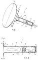
- FIG. 1 is a simplified, partially in section fragmentary side view of an air bag module installation in accordance with one embodiment of the invention, with the air bag deployed.
- FIG. 2 is a simplified, partially in section side view of the air bag module assembly of FIG. 1 prior to deployment of the air bag.
- FIG. 3 is a simplified, enlarged, fragmentary, partially in section side view of the air bag module assembly installation of FIG. 1 prior to deployment of the air bag.
- FIG. 4 is a plan view taken along line 4-4 of FIG. 2 and viewed in the direction of the arrows of the air bag module assembly.
- FIG. 5 is a simplified, partially in section side view, similar to FIG. 2, of an air bag module assembly in accordance with an alternative embodiment of the invention.
- FIG. 6 is an enlarged, fragmentary, partially in section, side view of a portion of an air bag module assembly in accordance with yet another embodiment of the invention.
- FIG. 7 is a simplified, partially in section side view, similar to FIG. 2, of an air bag module assembly in accordance with yet still another alternative embodiment of the invention.
- the present invention provides an improved air bag module assembly and combinations therewith for use in inflatable passive restraint systems for use in vehicles for restraining the movement of a seated occupant during a collision.
- FIGS. 1-4 there is illustrated an air bag module installation, generally designated by the reference numeral 10, in accordance with one embodiment of the invention.
- an air bag module assembly 11 is installed in a vehicle steering shaft 12, specifically, within an elongated hollow 14 in the vehicle steering shaft 12.
- the steering shaft hollow 14 is formed to have an open end 16, adjacent the steering wheel 20, and a closed opposite end 22.
- the air bag module assembly 11 is cylindrical in cross section and includes a module housing 24 formed by an elongated tubular member 26 having an inner surface 27 and an outer surface 28 and including a first end 30 and a second end 32.
- the first end 30 is open and the second end 32 is closed.
- Air bag inflator devices suitable for use include devices in which the principal source of inflation gas is:
- an air bag 42 housed or disposed within the housing tubular member 26, in a collapsed condition, is an air bag 42 with an inlet opening 43.
- the inflator device 34 upon actuation, the inflator device 34 emits inflation gas (depicted by arrows 44) from the first inflator device axial end 36, resulting in deployment and inflation of the air bag 42.
- the open first end 30 of the housing tubular member 26 forms an outwardly extending mounting flange 46.
- the air bag inlet opening 43 is retained to the housing tubular member 26 between an annular air bag retaining ring 52 and the mounting flange 46.
- the air bag retaining ring 52 is temporarily held to the air bag module housing 24, specifically the mounting flange 46, by holding means such as by means of an adhesive such as an acrylic pressure sensitive adhesive such as 3M-439, by 3M.
- the air bag 42 is collapsed and inverted upon itself and positioned within the housing 26.
- the use of such an inverted air bag in the module assembly of the invention can reduce or eliminate the need for the relatively complex and exact air bag folding required in those air bag module assemblies wherein, as described above, the air bag is stored or housed outside of the plane of the steering wheel.
- a protective covering 54 such as of reinforced paper or rupturable plastic can be placed in covering relation to the open end 30 of the housing 26, adjacent the air bag retaining ring 52 and opposite the mounting flange 46.
- the protective covering 54 can be joined to the air bag retaining ring by means of a suitable adhesive, such as an acrylic pressure sensitive adhesive such as 3M-439, by 3M, or other suitable method of joinder.
- the protective covering 54 provides a seal between the internal components of the assembly 11 and the outer surrounding environment and thus serves as a barrier to the undesired entry of objects into the module assembly as well as helping to ensure that the air bag is properly retained and maintained in an inverted state during assembly handling and installation.
- the assembly 11 is nested completely within the vehicle steering shaft 12, where it is hidden.
- Such installation and attachment can be effected by means of fasteners 60 passed through the assembly 11, e.g., fastener openings 62 in the protective covering 54, the air bag retaining ring 52, the air bag 42, and the mounting flange 46.
- an outer cover 64 such as positioned at the steering wheel center 66, can be provided.
- the air bag system is triggered into operation with gas emanating from the inflator device 34 within the tubular housing 26.
- the air bag 42 starts to invert and deploy.
- the covering 54 ruptures or otherwise permits deployment of the air bag 42 out of the open first end 30 of the housing member 26 and against the inner surface 70 of the outer cover 64.
- the outer cover 64 will tear or otherwise open such as along a pre-form tear seam 72, such as is known in the art, permitting the deployment of the air bag 42 therethrough.
- FIG. 5 is similar to FIG. 2 and shows an air bag module assembly 111 in accordance with an alternative embodiment of the invention.
- the air bag module assembly 111 includes a module housing 124 formed by an elongated tubular member 126 having a first end 130 and a second end 132.
- an air bag inflator device 134 Disposed within the housing tubular member 126 is an air bag inflator device 134 having opposed first and second axial ends, 136 and 140, respectively.
- both the first and second ends, 130 and 132, respectively, of the housing tubular member 126 are initially open, with the second end 132 being crimped to form a mechanical lock 174 about an attachment indentation 176 at the second axial end 140 of the inflator device 134.
- Such an arrangement not only provides for the attachment of the inflator within the housing but also forms a closure for one end of the housing tubular member, as a tube that is open ended (as shown in FIG. 5) can be less costly and difficult to form than a similarly sized and shaped closed end tube (as shown in FIG. 2).
- the embodiment of FIG. 5 includes a particulate filter 180 disposed within the housing tubular member 126 between the inflation gas emitting first axial end 136 of the inflator device 134 and the inlet opening 143 of the air bag 142.
- the particulate filter 180 is in the form of a U-shaped particulate filter device 182 formed of a suitable material such as a metal wire screen material, such as a 30 mesh carbon steel.
- the U-shaped particulate filter device 182 includes a closed base portion 183 and an open mouth portion 184 and has inner and outer surfaces, 186 and 188, respectively.
- a filter device to effect particulate removal will be particularly desired in those assemblies which include inflator devices that utilize a combustible gas generating material, e.g., a pyrotechnic, which may produce significant amounts of particulate.
- a combustible gas generating material e.g., a pyrotechnic
- such particulate filter device can also include a filter media such as of ceramic paper or steel wool housed between one or more layers of suitable metal wire screen material, such as to effect improved particulate filtration.
- a filter media such as of ceramic paper or steel wool housed between one or more layers of suitable metal wire screen material, such as to effect improved particulate filtration.
- the inflation gas emitting first axial end 136 of the inflator device 134 is disposed within the open mouth portion 184 of the U-shaped particulate filter device 182 and adjacent inner surface 186 of the filter device 182 along the closed base portion 183 thereof.
- the arrangement illustrated in FIG. 5 can provide various manufacturing and/or assembly advantages.
- such an arrangement can be utilized to permit the filter device to be pre-assembled with the inflator device, e.g., the filter device can be tack welded to the inflator device, prior to installation of such pre-assembled arrangement in the module housing.
- FIG. 6 illustrates an air bag module assembly 211 similar to the assembly 111 shown in FIG. 5 and including a module housing 224 formed by an elongated tubular member 226. Disposed within the housing tubular member 226 is an air bag inflator device 234 having a first axial end 236 wherefrom, upon actuation, inflation gas is discharged. Also housed or disposed within the housing tubular member 226, in a collapsed condition, is an air bag 242. In addition, the assembly 211 is a particulate filter 280 disposed within the housing tubular member 226 between the inflation gas emitting first axial end 236 of the inflator device 234 and the air bag 242.
- the assembly 211 also includes an annular baffle 290 joined to the inner surface 227 of tubular housing member 226 and positioned between the inflation gas emitting first axial end 236 of the inflator device 234 and the air bag 242, specifically between the particulate filter 280 and the air bag 242.
- a baffle can be fabricated of a material such as of steel similar to that used in the fabrication of the housing member 226 and can be included in those assemblies where gas flow redirection is desired.
- a baffle can be included such as to effect gas flow redirection whereby the gas flow is directed towards the bottom 292 of the inverted air bag 242 rather than along the inner surface 227 of the tubular housing member 226.
- baffles can be included within the housing member such as to effect further gas flow redirection.
- FIG. 7 illustrates an air bag module assembly 311 in accordance with yet another embodiment of the invention.
- the air bag module assembly 311 is similar to the assembly 111 shown in FIG. 5, however, the particulate filter 380 disposed within the housing tubular member 326 between the inflation gas emitting first axial end 336 of the inflator device 334 and the inlet opening 343 of the air bag 342 has an inverted orientation. That is, the inflator device 334 is disposed adjacent the outer surface 388 of filter device 382 along the closed base portion 383 thereof.
- FIG. 7 can provide various manufacturing and/or assembly advantages.
- such an arrangement can be utilized to permit the filter device to be attached within the tubular module housing prior to insertion of the inflator as the so pre-attached filter device can then act as a stop to limit the extent to which the inflator device is inserted within the tubular module housing.
- the steering shaft of a vehicle typically functions as a structural member of the vehicle and is commonly fabricated of hardened, alloy steel in order to be better able to withstand the large forces to which the steering shaft may be subjected.
- the housing of an inflator device and an air bag, such as a part of an air bag module assembly unit as described herein, within a vehicular steering shaft makes for a more efficient utilization of the structural strength present in the steering shaft and thus allows for greater design freedom.
- the housing of the assembly and/or the inflator device housed therein can be fabricated of lighter weight or thickness material, e.g., steel, resulting in desired cost and weight savings.
- the invention thus provides an arrangement wherein an air bag and air bag assembly can be readily concealed within a steering wheel such that, prior to deployment, the location and placement of the air bag and assembly are not obvious and prominent to a passenger or other viewer of the vehicle interior. Further, the arrangement of the invention provides for greater design and styling freedom, such as may result in improved ergonomic design of the vehicle interior.
- the invention has been described hereinabove with particular reference to a driver side air bag module assembly for automotive vehicles including vans, pick-up trucks, and particularly automobiles, it is to be understood that the invention also has applicability, in at least certain aspects, for other types or kinds of air bag assemblies.
- the cylindrical air bag module assemblies of the invention may because of considerations such as size or geometry find application in passenger side and side impact air bag assemblies.
Landscapes
- Engineering & Computer Science (AREA)
- Mechanical Engineering (AREA)
- Air Bags (AREA)
Applications Claiming Priority (2)
| Application Number | Priority Date | Filing Date | Title |
|---|---|---|---|
| US371337 | 1995-01-11 | ||
| US08/371,337 US5609356A (en) | 1995-01-11 | 1995-01-11 | Cylindrical air bag module assembly |
Publications (3)
| Publication Number | Publication Date |
|---|---|
| EP0721865A2 true EP0721865A2 (fr) | 1996-07-17 |
| EP0721865A3 EP0721865A3 (fr) | 1996-11-20 |
| EP0721865B1 EP0721865B1 (fr) | 2000-05-24 |
Family
ID=23463555
Family Applications (1)
| Application Number | Title | Priority Date | Filing Date |
|---|---|---|---|
| EP96300164A Expired - Lifetime EP0721865B1 (fr) | 1995-01-11 | 1996-01-09 | Module cylindrique de sac gonflable |
Country Status (4)
| Country | Link |
|---|---|
| US (1) | US5609356A (fr) |
| EP (1) | EP0721865B1 (fr) |
| JP (1) | JP3025760U (fr) |
| DE (1) | DE69608472T2 (fr) |
Cited By (4)
| Publication number | Priority date | Publication date | Assignee | Title |
|---|---|---|---|---|
| WO1998028166A2 (fr) | 1996-12-21 | 1998-07-02 | Volkswagen Aktiengesellschaft | Systeme de retenue monte dans le volant pour vehicule a moteur |
| EP1211145A1 (fr) | 2000-11-25 | 2002-06-05 | Volkswagen Aktiengesellschaft | Coussin gonflable dans un volant pour un véhicule |
| DE202004013302U1 (de) * | 2004-08-25 | 2005-01-20 | Trw Automotive Gmbh | Gassack-Modul |
| EP3661816A4 (fr) * | 2017-08-04 | 2020-12-30 | Byton Limited | Dispositifs de type coussin de sécurité gonflable conçus pour utiliser une zone de surface intérieure réduite d'un véhicule |
Families Citing this family (23)
| Publication number | Priority date | Publication date | Assignee | Title |
|---|---|---|---|---|
| DE19546232B4 (de) * | 1995-09-22 | 2004-05-19 | Takata-Petri Ag | Vorrichtung zur Faltung eines Gassackes für ein Airbagmodul |
| DE19616977C1 (de) * | 1996-04-27 | 1997-04-10 | Autoliv Dev | Lenkrad mit integrierter Airbag-Einheit |
| US5893580A (en) * | 1996-05-22 | 1999-04-13 | Hoagland; Larry D. | Motor vehicle steering column safety device |
| JPH10236256A (ja) * | 1997-02-26 | 1998-09-08 | Tokai Rika Co Ltd | エアバッグ装置 |
| DE59809761D1 (de) * | 1997-04-16 | 2003-11-06 | Volkswagen Ag | Lenksäule für Insassenschutzeinrichtungen und Sicherheitslenkungen |
| US6457738B1 (en) | 1997-06-09 | 2002-10-01 | Textron Automotive Company, Inc. | Inflatable restraint apparatus |
| US6533312B1 (en) * | 1997-06-09 | 2003-03-18 | Textron Automotive Company, Inc. | Inflatable restraint apparatus |
| US6227571B1 (en) * | 1999-11-03 | 2001-05-08 | Trw Vehicle Safety Systems Inc. | Telescoping vehicle steering column apparatus for helping to protect a vehicle driver |
| DE10012093A1 (de) * | 2000-03-15 | 2001-09-20 | Volkswagen Ag | Lenkvorrichtung für ein Fahrzeug, insbesondere für ein Kraftfahrzeug, mit einem Airbagmodul |
| DE10207885A1 (de) * | 2002-02-20 | 2003-09-04 | Takata Petri Ag | Airbaganordnung |
| DE20303685U1 (de) * | 2003-03-07 | 2003-05-28 | Schreiner GmbH & Co. KG, 85764 Oberschleißheim | Selbstklebende Abdeckung zur Verklebung über Kanten |
| WO2006034436A2 (fr) | 2004-09-21 | 2006-03-30 | Stout Medical Group, L.P. | Dispositif de support expansible et procede d'utilisation |
| WO2007009107A2 (fr) | 2005-07-14 | 2007-01-18 | Stout Medical Group, P.L. | Dispositif de support dilatable et sa methode d'utilisation |
| JP5542273B2 (ja) | 2006-05-01 | 2014-07-09 | スタウト メディカル グループ,エル.ピー. | 拡張可能な支持装置および使用方法 |
| WO2010056895A1 (fr) | 2008-11-12 | 2010-05-20 | Stout Medical Group, L.P. | Dispositif de fixation et procédé correspondant |
| US20100211176A1 (en) | 2008-11-12 | 2010-08-19 | Stout Medical Group, L.P. | Fixation device and method |
| US8535380B2 (en) | 2010-05-13 | 2013-09-17 | Stout Medical Group, L.P. | Fixation device and method |
| EP2608747A4 (fr) | 2010-08-24 | 2015-02-11 | Flexmedex Llc | Dispositif de soutien et procédé d'utilisation associé |
| US9149286B1 (en) | 2010-11-12 | 2015-10-06 | Flexmedex, LLC | Guidance tool and method for use |
| JP2014529445A (ja) | 2011-08-23 | 2014-11-13 | フレックスメデックス,エルエルシー | 組織除去装置及び方法 |
| US10583855B2 (en) * | 2017-09-05 | 2020-03-10 | Byton Gmbh | Steering device for a vehicle, in particular an electric vehicle |
| US10457239B2 (en) | 2017-11-27 | 2019-10-29 | Autoliv Asp, Inc. | Frontal airbag systems and uses thereof |
| US11407436B2 (en) | 2019-03-04 | 2022-08-09 | Byton North America Corporation | Steering wheel with fixed center |
Family Cites Families (19)
| Publication number | Priority date | Publication date | Assignee | Title |
|---|---|---|---|---|
| US3600003A (en) * | 1969-03-19 | 1971-08-17 | Eaton Yale & Towne | Vehicle safety system |
| US3632135A (en) * | 1969-09-15 | 1972-01-04 | Eaton Yale & Towne | Reservoir in the steering column |
| US3649045A (en) * | 1970-01-27 | 1972-03-14 | Ensign Bickford Co | Fluid supply device for vehicle safety system |
| GB1307183A (en) * | 1970-05-04 | 1973-02-14 | Nissan Motor | Vehicular safety device |
| DE2034008A1 (de) * | 1970-07-09 | 1972-01-13 | Daimler Benz Ag, 7000 Stuttgart | Sicherheitslenkung fur Kraftwagen |
| FR2098804A5 (fr) * | 1970-07-28 | 1972-03-10 | Peugeot & Renault | |
| JPS507334B1 (fr) * | 1970-12-25 | 1975-03-25 | ||
| DE2115302A1 (de) * | 1971-03-30 | 1972-10-12 | Messerschmitt Bolkow Blohra GmbH, 8000 München | Fahrzeug zur Personenbeförderung, insbesondere Personenkraftwagen, mit einem Stoßdampfungssystem |
| US3784223A (en) * | 1971-06-10 | 1974-01-08 | Eaton Corp | Safety apparatus |
| US3843151A (en) * | 1972-04-10 | 1974-10-22 | Allied Chem | Particle engaging screen device for pyro-technic system |
| US3863948A (en) * | 1973-10-05 | 1975-02-04 | Olin Corp | Rotary connection for a safety bag inflation system |
| US3909037A (en) * | 1974-05-22 | 1975-09-30 | Olin Corp | Safety device with coanda effect |
| US4111457A (en) * | 1975-12-19 | 1978-09-05 | Bayerische Motoren Werke Ag | Inflatable restraining device for motor vehicles |
| US4275901A (en) * | 1978-07-21 | 1981-06-30 | Honda Giken Kogyo Kabushiki Kaisha | Inflatable safety bag system for vehicles |
| US4500114A (en) * | 1982-08-27 | 1985-02-19 | Thiokol Corporation | Device for controlled differential flow |
| GB2202142A (en) * | 1987-03-17 | 1988-09-21 | Graviner Ltd | Passive restraints |
| US4913461A (en) * | 1988-12-27 | 1990-04-03 | Talley Automotive Products, Inc. | Airbag module and method of making same |
| FR2702724B1 (fr) * | 1993-03-18 | 1995-06-16 | Ecia Equip Composants Ind Auto | Ensemble de colonne de direction muni d'un module à sac gonflable, notamment pour véhicule automobile. |
| DE4418628A1 (de) * | 1994-05-27 | 1995-11-30 | Trw Repa Gmbh | Insassen-Rückhaltesystem für die Fahrerseite in einem Fahrzeug |
-
1995
- 1995-01-11 US US08/371,337 patent/US5609356A/en not_active Expired - Fee Related
- 1995-12-13 JP JP1995013211U patent/JP3025760U/ja not_active Expired - Lifetime
-
1996
- 1996-01-09 EP EP96300164A patent/EP0721865B1/fr not_active Expired - Lifetime
- 1996-01-09 DE DE69608472T patent/DE69608472T2/de not_active Expired - Fee Related
Cited By (4)
| Publication number | Priority date | Publication date | Assignee | Title |
|---|---|---|---|---|
| WO1998028166A2 (fr) | 1996-12-21 | 1998-07-02 | Volkswagen Aktiengesellschaft | Systeme de retenue monte dans le volant pour vehicule a moteur |
| EP1211145A1 (fr) | 2000-11-25 | 2002-06-05 | Volkswagen Aktiengesellschaft | Coussin gonflable dans un volant pour un véhicule |
| DE202004013302U1 (de) * | 2004-08-25 | 2005-01-20 | Trw Automotive Gmbh | Gassack-Modul |
| EP3661816A4 (fr) * | 2017-08-04 | 2020-12-30 | Byton Limited | Dispositifs de type coussin de sécurité gonflable conçus pour utiliser une zone de surface intérieure réduite d'un véhicule |
Also Published As
| Publication number | Publication date |
|---|---|
| DE69608472D1 (de) | 2000-06-29 |
| US5609356A (en) | 1997-03-11 |
| DE69608472T2 (de) | 2000-09-14 |
| EP0721865B1 (fr) | 2000-05-24 |
| JP3025760U (ja) | 1996-06-25 |
| EP0721865A3 (fr) | 1996-11-20 |
Similar Documents
| Publication | Publication Date | Title |
|---|---|---|
| EP0721865B1 (fr) | Module cylindrique de sac gonflable | |
| JP3760424B2 (ja) | 車両用エアバッグ装置 | |
| US6588793B2 (en) | Thin airbag module design for overhead applications | |
| US5531476A (en) | Occupant restraint system for motor vehicles with an airbag | |
| US5533750A (en) | Simplified inflatable restraint module | |
| CA2099834C (fr) | Coussin d'air pour la protection lors d'impact lateral | |
| JP2721719B2 (ja) | エアバッグモジュールとその組立法 | |
| US6886855B2 (en) | Gas generant filter assemblies | |
| US6224088B1 (en) | Inflatable occupant protection device extending adjacent a windshield | |
| US7213837B2 (en) | Airbag module | |
| JP3047916U (ja) | エアバッグ装置、エアバッグ膨張器組立体、及び、膨張器及びクッションの双方を保持するための保持装置 | |
| WO2005016702A2 (fr) | Airbag pour passager a double coussin | |
| JPH08230596A (ja) | 同乗者用エアバック拘束装置 | |
| JPH09164895A (ja) | 自動車用エアバッグモジュール | |
| US6409210B1 (en) | Integrated side air curtain and inflator overhead system | |
| US5441299A (en) | Air bag inflator subassembly for installation onto the dashboard substrate of a motor vehicle | |
| JP2501416B2 (ja) | 搭乗者制止装置におけるカバ―保持方法 | |
| JP3278463B2 (ja) | 自動車のエアバッグ配設構造 | |
| US5498024A (en) | Inflatable restraint assembly | |
| US5419584A (en) | Air bag retention clip | |
| US5566975A (en) | Controlled pressure relief of an inflatable restraint reaction canister | |
| US5458363A (en) | Cylindrical inflator retainer ring | |
| JP3262599B2 (ja) | 自動車のエアバッグ配設構造 | |
| US7118128B2 (en) | Low leakage airbag module | |
| JP4051155B2 (ja) | 自動車用エアバッグ装置 |
Legal Events
| Date | Code | Title | Description |
|---|---|---|---|
| PUAI | Public reference made under article 153(3) epc to a published international application that has entered the european phase |
Free format text: ORIGINAL CODE: 0009012 |
|
| AK | Designated contracting states |
Kind code of ref document: A2 Designated state(s): DE FR GB IT |
|
| PUAL | Search report despatched |
Free format text: ORIGINAL CODE: 0009013 |
|
| AK | Designated contracting states |
Kind code of ref document: A3 Designated state(s): DE FR GB IT |
|
| 17P | Request for examination filed |
Effective date: 19970509 |
|
| 17Q | First examination report despatched |
Effective date: 19990215 |
|
| GRAG | Despatch of communication of intention to grant |
Free format text: ORIGINAL CODE: EPIDOS AGRA |
|
| GRAG | Despatch of communication of intention to grant |
Free format text: ORIGINAL CODE: EPIDOS AGRA |
|
| GRAH | Despatch of communication of intention to grant a patent |
Free format text: ORIGINAL CODE: EPIDOS IGRA |
|
| GRAH | Despatch of communication of intention to grant a patent |
Free format text: ORIGINAL CODE: EPIDOS IGRA |
|
| RAP1 | Party data changed (applicant data changed or rights of an application transferred) |
Owner name: AUTOLIV ASP, INC. |
|
| GRAA | (expected) grant |
Free format text: ORIGINAL CODE: 0009210 |
|
| AK | Designated contracting states |
Kind code of ref document: B1 Designated state(s): DE FR GB IT |
|
| PG25 | Lapsed in a contracting state [announced via postgrant information from national office to epo] |
Ref country code: IT Free format text: LAPSE BECAUSE OF FAILURE TO SUBMIT A TRANSLATION OF THE DESCRIPTION OR TO PAY THE FEE WITHIN THE PRE;WARNING: LAPSES OF ITALIAN PATENTS WITH EFFECTIVE DATE BEFORE 2007 MAY HAVE OCCURRED AT ANY TIME BEFORE 2007. THE CORRECT EFFECTIVE DATE MAY BE DIFFERENT FROM THE ONE RECORDED.SCRIBED TIME-LIMIT Effective date: 20000524 |
|
| REF | Corresponds to: |
Ref document number: 69608472 Country of ref document: DE Date of ref document: 20000629 |
|
| ET | Fr: translation filed | ||
| PLBE | No opposition filed within time limit |
Free format text: ORIGINAL CODE: 0009261 |
|
| STAA | Information on the status of an ep patent application or granted ep patent |
Free format text: STATUS: NO OPPOSITION FILED WITHIN TIME LIMIT |
|
| 26N | No opposition filed | ||
| REG | Reference to a national code |
Ref country code: GB Ref legal event code: IF02 |
|
| PGFP | Annual fee paid to national office [announced via postgrant information from national office to epo] |
Ref country code: GB Payment date: 20031230 Year of fee payment: 9 |
|
| PG25 | Lapsed in a contracting state [announced via postgrant information from national office to epo] |
Ref country code: GB Free format text: LAPSE BECAUSE OF NON-PAYMENT OF DUE FEES Effective date: 20050109 |
|
| GBPC | Gb: european patent ceased through non-payment of renewal fee |
Effective date: 20050109 |
|
| PGFP | Annual fee paid to national office [announced via postgrant information from national office to epo] |
Ref country code: DE Payment date: 20070124 Year of fee payment: 12 |
|
| PGFP | Annual fee paid to national office [announced via postgrant information from national office to epo] |
Ref country code: FR Payment date: 20070125 Year of fee payment: 12 |
|
| PG25 | Lapsed in a contracting state [announced via postgrant information from national office to epo] |
Ref country code: DE Free format text: LAPSE BECAUSE OF NON-PAYMENT OF DUE FEES Effective date: 20080801 |
|
| REG | Reference to a national code |
Ref country code: FR Ref legal event code: ST Effective date: 20081029 |
|
| PG25 | Lapsed in a contracting state [announced via postgrant information from national office to epo] |
Ref country code: FR Free format text: LAPSE BECAUSE OF NON-PAYMENT OF DUE FEES Effective date: 20080131 |