EP0721920A1 - UV-Bestrahlungsreaktor zur Flüssigkeitenreinigung - Google Patents
UV-Bestrahlungsreaktor zur Flüssigkeitenreinigung Download PDFInfo
- Publication number
- EP0721920A1 EP0721920A1 EP96460001A EP96460001A EP0721920A1 EP 0721920 A1 EP0721920 A1 EP 0721920A1 EP 96460001 A EP96460001 A EP 96460001A EP 96460001 A EP96460001 A EP 96460001A EP 0721920 A1 EP0721920 A1 EP 0721920A1
- Authority
- EP
- European Patent Office
- Prior art keywords
- reactor
- liquid
- treated
- reactor according
- active chamber
- Prior art date
- Legal status (The legal status is an assumption and is not a legal conclusion. Google has not performed a legal analysis and makes no representation as to the accuracy of the status listed.)
- Granted
Links
Images



Classifications
-
- C—CHEMISTRY; METALLURGY
- C02—TREATMENT OF WATER, WASTE WATER, SEWAGE, OR SLUDGE
- C02F—TREATMENT OF WATER, WASTE WATER, SEWAGE, OR SLUDGE
- C02F1/00—Treatment of water, waste water, or sewage
- C02F1/30—Treatment of water, waste water, or sewage by irradiation
- C02F1/32—Treatment of water, waste water, or sewage by irradiation with ultraviolet light
- C02F1/325—Irradiation devices or lamp constructions
-
- A—HUMAN NECESSITIES
- A61—MEDICAL OR VETERINARY SCIENCE; HYGIENE
- A61L—METHODS OR APPARATUS FOR STERILISING MATERIALS OR OBJECTS IN GENERAL; DISINFECTION, STERILISATION OR DEODORISATION OF AIR; CHEMICAL ASPECTS OF BANDAGES, DRESSINGS, ABSORBENT PADS OR SURGICAL ARTICLES; MATERIALS FOR BANDAGES, DRESSINGS, ABSORBENT PADS OR SURGICAL ARTICLES
- A61L2/00—Disinfection or sterilisation of materials or objects, in general; Accessories therefor
- A61L2/02—Disinfection or sterilisation of materials or objects, in general; Accessories therefor using physical processes
- A61L2/08—Radiation
- A61L2/10—Ultraviolet [UV] radiation
-
- C—CHEMISTRY; METALLURGY
- C02—TREATMENT OF WATER, WASTE WATER, SEWAGE, OR SLUDGE
- C02F—TREATMENT OF WATER, WASTE WATER, SEWAGE, OR SLUDGE
- C02F2201/00—Apparatus for treatment of water, waste water or sewage
- C02F2201/32—Details relating to UV-irradiation devices
- C02F2201/322—Lamp arrangement
- C02F2201/3223—Single elongated lamp located on the central axis of a turbular reactor
-
- C—CHEMISTRY; METALLURGY
- C02—TREATMENT OF WATER, WASTE WATER, SEWAGE, OR SLUDGE
- C02F—TREATMENT OF WATER, WASTE WATER, SEWAGE, OR SLUDGE
- C02F2201/00—Apparatus for treatment of water, waste water or sewage
- C02F2201/32—Details relating to UV-irradiation devices
- C02F2201/322—Lamp arrangement
- C02F2201/3228—Units having reflectors, e.g. coatings, baffles, plates, mirrors
-
- C—CHEMISTRY; METALLURGY
- C02—TREATMENT OF WATER, WASTE WATER, SEWAGE, OR SLUDGE
- C02F—TREATMENT OF WATER, WASTE WATER, SEWAGE, OR SLUDGE
- C02F2201/00—Apparatus for treatment of water, waste water or sewage
- C02F2201/32—Details relating to UV-irradiation devices
- C02F2201/328—Having flow diverters (baffles)
Definitions
- the present invention relates to the disinfection of liquids, in particular drinking water or waste water, contaminated by microorganisms, using high or medium pressure UV lamps.
- the invention relates to various original provisions making it possible to improve the efficiency of high or medium pressure UV disinfection.
- Microorganisms subjected to a bombardment of UV photons, undergo modifications of their DNA which can prevent their replication.
- the statistical proportion of microorganisms of a given type thus inactivated within a given population is proportional to the UV dose (product of the radiation intensity by the exposure time) received by the population considered.
- UV emitters Two main types of UV emitters are currently commercially available.
- UV lamps with low mercury vapor pressure (UV lamps - BP) which have the advantage of emitting an almost monochromatic radiation, over 254 nm, therefore at the wavelength of optimal germicidal efficiency, but which have l disadvantage of being limited in unit power.
- Commercial UV - BP lamps are currently available in the range of 50 - 200 watts approximately. A large number of lamps must therefore generally be installed to treat an average wastewater flow.
- UV lamps with high or medium mercury vapor pressure have an emission spectrum which is more spread out and are therefore of less germicidal efficiency, but have a unit power which can be very high. (3 kw, 10 kw and up to 100 kw lamps are currently available). It should be noted that, in the context of this description, the UV emitters of a high or medium pressure are designated as power of at least 500 w, conventionally from 3 to 100 kw.
- UV reactors Basically two types are used in the water treatment.
- reactors of the open type, or channel in which the liquid in gravity flow with free surface passes in the middle of a multitude of equidistributed lamps parallel to each other in the channel (in vertical, horizontal or inclined position).
- closed type reactors generally under pressure, in which the water to be treated circulates in a chamber containing one or more UV emitters parallel to the axis of the chamber and distributed at a constant pitch in a given section of bedroom.
- Such closed type reactors can in particular be constituted by a UV emitter disposed coaxially inside a protective sheath transparent to UV, the assembly constituted by said emitter and said sheath being itself installed coaxially inside of a tubular ferrule, the liquid to be treated transiting in a tubular flow in an active chamber delimited by the inner face of said ferrule and the outer face of said sheath. It is more precisely to this type of closed reactor that the invention relates.
- reactors are in particular described in US-A-4,273,660, EP-A-3,924,349 or also WO 93/02965.
- reactors of this type may comprise several emitters and several active chambers, each emitter being arranged coaxially in a protective sheath transparent to UV and each emitter serving a single active chamber.
- UV lamps - HP or MP tends to prevail in the field of drinking water treatment, insofar as the compactness, simplicity, and the economy on investment allowed by the use of UV lamps - HP in closed reactors more than compensates for the increase in electricity consumption due to the lower germicidal efficiency of UV - HP or UV - MP lamps compared to UV - BP lamps.
- UV-BP lamps which have a better germicidal efficiency of the radiation produced, are therefore often often preferred in wastewater treatment.
- UV-HP (or MP) reactors with a coaxial lamp available commercially and described in the literature do not make it possible to minimize the energy loss linked to the fouling of the UV emitting elements.
- closed-type reactors also do not make it possible to standardize the residence time in the reactor by effectively and inexpensively limiting equipment, the significant short hydraulic circuits induced by the off-center inlet and outlet of the liquid to be treat in the reactor.
- the main objective of the present invention is to improve the efficiency of reactors with coaxial UV - HP or UV - MP lamp so as to make them economically advantageous for the treatment of such liquids, by delaying the fouling of the active chamber and sheath protecting the UV emitter of such a reactor by allowing their automatic fouling when necessary.
- Another objective of the invention is to improve the germicidal efficiency of UV - HP or MP disinfection devices using a lamp coaxial with a tube by optimizing the irradiation dose of each particle of the liquid treated in such a reactor and by improving the turbulence of this liquid.
- a UV irradiation reactor of the closed type, for the disinfection of liquids comprising at least one high or medium pressure UV emitter.
- the assembly constituted by said transmitter and said sheath being installed coaxially inside a tubular shell whose inner face reflects at least 30% of UV 250 at 260 nm incidents from said transmitter, the liquid to be treated transits in a tubular flow in an active chamber delimited by said inner face of said ferrule and the outer face of said sheath, said reactor being characterized in that it is connected to means for washing said active chamber including means for circulating a cleaning liquid in said active chamber and to means s air injection provided upstream of said active chamber allowing in particular improve the turbulence of said cleaning liquid during washing.
- said reactor also includes air injection means making it possible to improve the turbulence of the cleaning liquid during washing.
- the air thus used makes it possible to "assist" the cleaning liquid without having in itself a marked cleaning effect.
- Such washing means can be implemented according to a timetable, but preferably, the reactor according to the invention will include means for automatically activating the washing means.
- These automatic activation means may preferably comprise a UV sensor provided at the level of the reactor shell and making it possible to evaluate the UV transmission of the blade of liquid present in the active chamber of the reactor and the fouling rate of this chamber.
- said washing means include means making it possible to recycle said cleaning liquid.
- these washing means also comprise means for readjusting the title thereof.
- the reactor includes means for automatically activating said washing means.
- said activation means comprise a UV sensor provided at the level of said shell of the reactor.
- the reactor comprises means for heating said liquid. cleaning.
- the inner face of the ferrule reflects at least 30% of the UV 250 to 360 nm incidents originating from the transmitter.
- the energy recovered thanks to such a characteristic is used for the disinfection of the parts of the flow furthest from the UV emitter, that is to say the parts of the flow that are the least irradiated.
- the invention therefore allows additional irradiation which improves the overall performance of the irradiation treatment.
- metals other than stainless steel also give good reflection results, such as aluminum, which however has a greater tendency to corrosion by the treated liquids, or chromium.
- said inner face of said ferrule can also be constituted by a metal layer obtained by electrolytic deposition.
- the reactor according to the invention is dimensioned so as to instill, at the flow rate considered of liquid to be treated, a Reynolds number greater than 6000 in the internal tubular flow of the reactor.
- the dose received by a particle passing through the reactor at a distance r from the emitter is essentially a function of this distance r according to the Beer-Lambert law.
- the dimensions of the reactor are therefore provided so that each element of the fluid to be treated receives a similar dose of irradiation and makes it possible to ensure a turbulent flow of Reynolds number greater than 6000.
- the Reynolds number of the fluid in flow will thus be between 10,000 and 60,000.
- said reactor has means making it possible to subject the liquid to be treated entering said active chamber to a symmetrical pressure drop at least three times greater than the asymmetric pressure drop observed by the liquid to be treated before it enters said reactor.
- Such a pressure drop contributes to obtaining a homogeneous distribution of the fluid to be treated in the active chamber of the reactor and therefore a good homogeneity of the residence times of each incoming particle which makes it possible to further optimize the operation of the reactor.
- such a pressure drop is obtained thanks to an injection chamber provided coaxial at one end of said ferrule and at least one tube allowing the introduction - preferably tangential - of the liquid to be treated in said reactor via said injection chamber, said injection chamber communicating with said active chamber by a circular slot.
- the reactor is intended to be placed in a larger chamber limiting the effect of the asymmetrical arrival of the liquid to be treated, and has in its lower part an annular space comprised between said tubular shell and said sheath protection and separated from said active chamber by a narrowed passage.
- the reactor comprises means for injecting at least one reagent capable of completing the disinfection and / or detoxifying said liquid, said injection means being provided upstream of said active chamber.
- at least one reagent ozone, hydrogen peroxide Certainly may be formed by the means of air injection cited above.
- said reactor comprises means for regulating the power of said transmitter as a function of one or more parameters chosen from the group consisting of the flow rate of treated liquid, the UV transmission of the treated liquid, the time elapsed since the last wash.
- the invention also relates to a method of using a reactor according to the invention characterized in that it consists in operating said transmitter when the washing means are used. Such a method makes it possible to extend the life of the transmitter.
- 10 transmitters 10 kw unit can treat, for example, a peak flow of 1000 m3 / h of a given wastewater, it will be more efficient to treat an average flow of 600 m3 / h with 10 lamps operating at 6 kw unit only with 6 transmitters at their nominal power of 10 kw.
- the invention therefore also covers a method of regulating a system of several HP / MP UV emitters according to which the power necessary for the treatment of a given overall flow is obtained by uniformly distributing the total power required over the number of available emitters. , rather than using only a few transmitters at their maximum power.
- the UV irradiation reactor shown includes a medium pressure UV lamp 1 with a nominal power of 6 kw and installed inside a protective sheath made of quartz (material transparent to UV) with an external diameter of 140 mm .
- the assembly constituted by the lamp 1 and its sheath 2 is disposed inside a metallic ferrule 3 with an internal diameter of 200 mm coaxial therewith.
- the inner wall of the ferrule 3 and the outer wall of the sheath 2 define an active chamber 4 inside which a liquid to be disinfected passes. This liquid enters the reactor through an inlet 12 located at the bottom thereof and leaves it after being irradiated by an outlet 13 provided at the head of the reactor.
- the active chamber 4 is dimensioned so as to allow the tubular flow of this liquid along a blade with a thickness of 30 mm. Note that in practice this thickness will be in other embodiments generally of the order of 1 to 10 cm. Furthermore, the length of irradiation authorized by the reactor shown is 1 m, while its volume to be cleaned is approximately 30 liters.
- the ferrule 3 is made of 316L stainless steel internally polished to grade 150.
- a sealing system with O-rings 9 isolates from the liquid medium the interior of the quartz sheath 2 and the electrical supply of the lamp 1.
- an injection chamber 5 of the liquid to be treated is provided in the lower part of the reactor shown.
- This chamber 5 is provided, as can be seen in Figure 2 with a tangential tube 6 through which the liquid to be treated enters the reactor.
- This tubing 6 ensures a rotary movement of the liquid in the injection chamber 5 which minimizes the input pressure drop and improves the hydraulic distribution of the fluid to be treated.
- a similar arrangement is made in the upper part of the reactor to further improve the homogeneity of the residence times of each particle of the fluid to be treated in the irradiation zone.
- the reactor described is also provided in its lower part with means 8 making it possible to inject pressurized air to improve the turbulence during the washing of the reactor as will be explained below.
- a purge 11 is provided in the upper part of the reactor so as to evacuate the air which has passed through it.
- the invention also covers the possibility of injecting ozone, hydrogen peroxide (or any other reagent capable of supplementing the disinfecting and / or detoxifying action of UV on the liquid to be treated), by means of these injection means 8 provided at the bottom of the reactor, taking advantage of the improvement in the photocatalytic activity enabled by the reflection of UV.
- a tubing on the body of the reactor allows the connection of a UV sensor 35 making it possible to measure the UV transmission coefficient of the blade of liquid passing through the active chamber 4 and / or the degree of fouling of the reactor.
- a temperature sensor 50 is also provided and allows protection against operation of the UV emitter without the presence of liquid to be treated, which would cause damage.
- the reactor is connected to washing means 30 of the chamber 4 of the reactor allowing it to be clogged.
- These washing means 30 are connected to the sensor 35 provided on the reactor and are started as soon as the UV transmission detected by this sensor goes below a predetermined threshold. They include a washing liquid tank 36 as well as a pipe 37 and a pump 31 allowing the washing liquid contained in said tank to be sent inside the chamber 4 of the reactor.
- These washing means also include a pipe 32 making it possible to recycle the washing liquid recovered at the head of the reactor in the tank 36.
- the reservoir 36 may be loaded with various acidic and / or basic chemicals and / or detergent. It will be noted that it will also be possible, in other embodiments of the invention, to choose to trigger the washing according to an established time schedule or even manually at more or less regular intervals. It will also be noted that provision may be made to heat the cleaning liquid used for example using an electric heating pin keeping the cleaning liquid in its tank at a temperature between 20 ° and 60 ° C.
- the washing efficiency is also improved by injecting air at the bottom of the reactor thanks to the injection means 8
- washing means make it possible to completely overcome the need for mechanical washing by scrapers such as those described for example in patents WO 92/22502 or EP O 467465A1, of limited effectiveness and unsafe reliability. .
- the washing of the reactor can be carried out while the emitter (UV) is in operation, thus limiting the aging of the UV emitters which is accelerated during repeated on-off cycles.
- the inlet valve 42 is closed and the washing reagent inlet valve 51 open.
- the outlet valve 45 is closed and, simultaneously, the recycling valve 46 open.
- the valve 51 is closed again, the liquid inlet valve 42 open and, with a programmed offset, the recycling valve 46 is closed and the liquid outlet valve treaty 45 open.
- the UV emitter will be isolated and switched off before washing, and the reactor drained of its water content to be treated before introduction of the cleaning liquid.
- the reactor according to FIGS. 1 to 3 was operated with waste water having a UV transmissibility of 40 to 46% at a flow rate of 40 m3 / h and with a washing with phosphoric acid at 5% every 24 hours .
- the following results on the reduction of coliform bacteria have been obtained: total coliforms input: 1 to 7.107 / 100 ml thermo-tolerant coliforms input: 1 to 6.106 / 100 ml total coliforms output (at 5.91 kw): ⁇ 408 per 100 ml thermo-tolerant coliforms output (at 5.91 kw): ⁇ 52 per 100 ml.
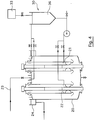
- FIG. 4 another embodiment of the reactor according to the invention is shown.
- two reactors are installed in a vertical position in a tank 20.
- the pressure drop at the inlet of the reactor is ensured by the proper symmetrical pressure drop of the active part of the reactor (narrowed passage 22 between the tubular shell 3 of the reactor and the UV transparent tubular sheath protecting the emitter), much greater than the asymmetric pressure drop generated by changes in the direction of the hydraulic flows in the buffer volume located under and around the reactors.
- the liquid to be treated arrives in the tank 20 via a pipe 23 and the treated liquid leaves the reactors by peripheral gutters 24 provided at the head of these reactors.
- the installation also includes washing means 30 similar to those of the embodiment shown in FIG. 3 with, in addition, readjustment means 33 for the title of the cleaning solution contained in the tank 36.
- common hydraulic distribution chambers 50 and 51 are produced in supply and outlet of a series of reactors (here, 2 reactors are shown) each comprising a UV emitter 1, a protective sheath transparent to UV 2, and an internally polished ferrule 3.
- the installation also includes washing means 60.
- the UV reactor may be placed in any position (horizontal, vertical or inclined) except when it is desired to add the possibility of an injection of compressed air or reactive gases, which preferably requires a vertical position (inlet of the fluid to be treated by the lower end of the reactor).
- the number of reactors and washing reagents can also be increased in a manner obvious to those skilled in the art without modification of the operating principle.
- several reactors can be put in parallel or in series, using n ' any of the hydraulic distribution means well known to those skilled in the art.
Landscapes
- Health & Medical Sciences (AREA)
- Life Sciences & Earth Sciences (AREA)
- Water Supply & Treatment (AREA)
- Hydrology & Water Resources (AREA)
- Engineering & Computer Science (AREA)
- Environmental & Geological Engineering (AREA)
- Toxicology (AREA)
- Chemical & Material Sciences (AREA)
- Organic Chemistry (AREA)
- Epidemiology (AREA)
- Animal Behavior & Ethology (AREA)
- General Health & Medical Sciences (AREA)
- Public Health (AREA)
- Veterinary Medicine (AREA)
- Physical Water Treatments (AREA)
Applications Claiming Priority (2)
| Application Number | Priority Date | Filing Date | Title |
|---|---|---|---|
| FR9500616 | 1995-01-16 | ||
| FR9500616A FR2729382B1 (fr) | 1995-01-16 | 1995-01-16 | Reacteur d'irradiation uv pour le traitement de liquides |
Publications (2)
| Publication Number | Publication Date |
|---|---|
| EP0721920A1 true EP0721920A1 (de) | 1996-07-17 |
| EP0721920B1 EP0721920B1 (de) | 2001-09-26 |
Family
ID=9475315
Family Applications (1)
| Application Number | Title | Priority Date | Filing Date |
|---|---|---|---|
| EP96460001A Expired - Lifetime EP0721920B1 (de) | 1995-01-16 | 1996-01-12 | UV-Bestrahlungsreaktor zur Flüssigkeitenreinigung |
Country Status (6)
| Country | Link |
|---|---|
| US (1) | US5725757A (de) |
| EP (1) | EP0721920B1 (de) |
| JP (1) | JPH08252575A (de) |
| CA (1) | CA2167112A1 (de) |
| DE (1) | DE69615419T2 (de) |
| FR (1) | FR2729382B1 (de) |
Cited By (4)
| Publication number | Priority date | Publication date | Assignee | Title |
|---|---|---|---|---|
| EP0809936A1 (de) * | 1996-05-29 | 1997-12-03 | Elsag Bailey (Canada) Inc. | Verfahren und Vorrichtung zur Bekämpfung von Zebramusscheln und anderen Schalentieren unter Anwendung von Ultraviolettstrahlung |
| WO2002049756A1 (en) * | 2000-12-21 | 2002-06-27 | Ciba Specialty Chemicals Water Treatments Limited | Tubular reactor qith coaxial cylinders and process using this reactor |
| US6565803B1 (en) | 1998-05-13 | 2003-05-20 | Calgon Carbon Corporation | Method for the inactivation of cryptosporidium parvum using ultraviolet light |
| IT202000007798A1 (it) | 2020-04-14 | 2021-10-14 | Medical Service S R L | Ascensore provvisto di apparecchiatura per l’abbattimento della carica di contaminazione e relativa apparecchiatura per l’abbattimento della carica di contaminazione per ascensori. |
Families Citing this family (38)
| Publication number | Priority date | Publication date | Assignee | Title |
|---|---|---|---|---|
| US5916439A (en) * | 1997-03-18 | 1999-06-29 | Safe Water Technologies, Inc. | Advanced safe water treatment system |
| US5942110A (en) * | 1997-12-29 | 1999-08-24 | Norris; Samuel C | Water treatment apparatus |
| AUPP158098A0 (en) * | 1998-01-29 | 1998-02-26 | Arnold, Geoffery Peter | Laser alignment apparatus and method |
| US6264836B1 (en) | 1999-10-21 | 2001-07-24 | Robert M. Lantis | Method and apparatus for decontaminating fluids using ultraviolet radiation |
| AU2001234172A1 (en) * | 2000-02-25 | 2001-09-03 | Ebara Corporation | Method and apparatus for electromagnetic irradiation of liquid |
| CA2306546C (en) | 2000-04-20 | 2006-06-27 | Photoscience Japan Corporation | Tube scraper |
| US7169311B2 (en) * | 2001-10-17 | 2007-01-30 | Honeywell International, Inc. | Apparatus for disinfecting water using ultraviolet radiation |
| RU2225364C1 (ru) * | 2002-07-18 | 2004-03-10 | Общество с ограниченной ответственностью Фирма "ЭЙКОСЪ" | Устройство для ультрафиолетового обеззараживания воды |
| WO2005062946A2 (en) * | 2003-12-23 | 2005-07-14 | San Diego State University Foundation | Perchlorate removal apparatus |
| GB2413005B (en) * | 2004-04-07 | 2007-04-04 | Jenact Ltd | UV light source |
| GB2418335B (en) | 2004-09-17 | 2008-08-27 | Jenact Ltd | Sterilising an air flow using an electrodeless UV lamp within microwave resonator |
| DE102004057076A1 (de) * | 2004-11-25 | 2006-06-22 | Wedeco Ag | Vorkammerreaktor |
| DE102004058405B4 (de) | 2004-12-03 | 2008-03-13 | Delta Uv Service Systeme | Vorrichtung zur UV-Bestrahlung von absorbierenden Flüssigkeiten im Durchfluss |
| US7159264B2 (en) | 2004-12-10 | 2007-01-09 | Calgon Carbon Corporation | Scraper for cleaning tubular members |
| NZ542509A (en) * | 2005-09-20 | 2008-01-31 | Logistic Solutions Ltd | A treatment system |
| JP2007144386A (ja) * | 2005-11-02 | 2007-06-14 | Toshiba Corp | 紫外線照射水処理装置 |
| JP4138797B2 (ja) * | 2005-11-25 | 2008-08-27 | 株式会社荏原製作所 | 紫外線照射装置 |
| US7780856B2 (en) * | 2006-07-28 | 2010-08-24 | Huei-Tarng Liou | Device for on-line light radiation in gas-containing liquid |
| RU2323161C1 (ru) * | 2006-12-22 | 2008-04-27 | Виктор Львович Зелезецкий | Устройство для ультрафиолетовой обработки жидкости в потоке |
| US7767978B1 (en) * | 2007-02-20 | 2010-08-03 | William Lim | Ultraviolet water treatment device |
| US8795600B2 (en) * | 2009-02-26 | 2014-08-05 | Zoeller Pump Company, Llc | UV disinfection system |
| GB0907338D0 (en) * | 2009-04-28 | 2009-06-10 | Snowball Malcolm R | Fluid disinfector |
| GB0918824D0 (en) | 2009-10-27 | 2009-12-09 | Waterlogic Internat Ltd | Water purification |
| AT509363B1 (de) * | 2010-03-01 | 2011-12-15 | Martin Wesian | Vorrichtung und verfahren zum ermitteln des desinfektionsgrades einer flüssigkeit |
| JP2014506482A (ja) | 2011-02-23 | 2014-03-17 | アムジエン・インコーポレーテツド | Uvc露光のための細胞培養培地およびそれに関連した方法 |
| US20120285894A1 (en) | 2011-05-13 | 2012-11-15 | Frank Leslie Smiddy | System and method for the treatment of wastewater |
| GB2494448A (en) * | 2011-09-09 | 2013-03-13 | Steriflow Ltd | Ultra-violet liquid steriliser |
| DE102012008733A1 (de) * | 2012-05-04 | 2013-11-07 | Xylem Water Solutions Herford GmbH | UV-Wasserbehandlungsanlage mit offenem Kanal |
| US9255025B2 (en) | 2012-07-20 | 2016-02-09 | ProAct Services Corporation | Method for the treatment of wastewater |
| KR101253322B1 (ko) * | 2012-11-21 | 2013-04-10 | 대한수처리주식회사 | 자외선 살균장치 |
| US11359397B2 (en) * | 2014-01-21 | 2022-06-14 | Egon GRUBER | Device for disinfecting water |
| WO2016028681A1 (en) * | 2014-08-18 | 2016-02-25 | Imi Cornelius, Inc. | Self-cleaning beverage nozzle |
| EP3224206B1 (de) * | 2014-11-27 | 2019-05-22 | Wallenius Water Innovation AB | Flüssigkeitsbehandlungsvorrichtung mit einem luftfallengefäss |
| JP6826836B2 (ja) * | 2016-08-09 | 2021-02-10 | 旭化成株式会社 | 紫外線照射装置 |
| CN107055895A (zh) * | 2017-06-16 | 2017-08-18 | 云南大学 | 一种上布流内扩散竖式推流光催化处理废水撬装设备 |
| RU2756004C1 (ru) * | 2019-06-25 | 2021-09-24 | Вячеслав Владимирович Вяткин | Резервуар для бактерицидного хранения воды |
| IT202100016301A1 (it) * | 2021-06-22 | 2022-12-22 | Spacecannonch Sagl | Dispositivo di sanificazione di fluidi. |
| US20230313111A1 (en) * | 2022-04-04 | 2023-10-05 | Arcology Inc. Dba Biosphere | Bioreactors configured for uv sterilization, and methods of using uv sterilization in bioprocesses |
Citations (6)
| Publication number | Priority date | Publication date | Assignee | Title |
|---|---|---|---|---|
| US4273660A (en) * | 1979-02-21 | 1981-06-16 | Beitzel Stuart W | Purification of water through the use of ozone and ultraviolet light |
| DE3414870A1 (de) * | 1984-04-19 | 1985-10-31 | René 8521 Möhrendorf Stein | Vorrichtung zur trinkwasserentkeimung fuer campingmobile |
| DE3924349A1 (de) * | 1989-07-22 | 1991-01-31 | Waterangel Wasseraufbereitungs | Entkeimungsgeraet fuer fluessigkeiten |
| EP0470518A1 (de) * | 1990-08-08 | 1992-02-12 | Ultra Systems Gmbh Uv-Oxidation | Vorrichtung zur Durchführung photochemischer Reaktionen |
| US5124131A (en) * | 1990-12-10 | 1992-06-23 | Ultraviolet Energy Generators, Inc. | Compact high-throughput ultraviolet processing chamber |
| WO1993002965A1 (de) * | 1991-07-26 | 1993-02-18 | Ultra Systems Gmbh Uv-Oxidation | Verfahren zur aufbereitung von mit organischen substanzen belastetem rohtrinkwasser |
Family Cites Families (14)
| Publication number | Priority date | Publication date | Assignee | Title |
|---|---|---|---|---|
| US2732502A (en) * | 1956-01-24 | darney | ||
| US4017734A (en) * | 1974-09-27 | 1977-04-12 | Ross Henry M | Water purification system utilizing ultraviolet radiation |
| CA1048733A (en) * | 1977-02-02 | 1979-02-20 | Ontario Research Foundation | Ozone/ultraviolet water purifier |
| DE2733344C2 (de) * | 1977-07-23 | 1979-07-12 | Alfred 7500 Karlsruhe Graentzel | Apparatur zur Bestrahlung strömungsfähiger Medien zum Erzielen chemischer Reaktionen bzw. Reaktionsprodukte |
| US4156652A (en) * | 1977-07-28 | 1979-05-29 | Reiner Wiest | Apparatus for sterilizing fluids with UV radiation and ozone |
| US4400270A (en) * | 1980-04-18 | 1983-08-23 | Adco Aerospace, Inc. | Ultraviolet apparatus for disinfection and sterilization of fluids |
| CA1163086A (en) * | 1981-11-30 | 1984-03-06 | Jan Maarschalkerweerd | Ultraviolet fluid purifying device |
| GB8513170D0 (en) * | 1985-05-24 | 1985-06-26 | Still & Sons Ltd W M | Water purifiers |
| US4963750A (en) * | 1986-12-09 | 1990-10-16 | Wilson Robert L | Fluid media sterilization apparatus |
| US4968489A (en) * | 1988-09-13 | 1990-11-06 | Peroxidation Systems, Inc. | UV lamp enclosure sleeve |
| US4872980A (en) * | 1988-09-13 | 1989-10-10 | Trojan Technologies, Inc. | Fluid purification device |
| JP2523214B2 (ja) * | 1990-07-17 | 1996-08-07 | 株式会社大氣社 | 塗料除去処理用洗浄設備 |
| US5133945A (en) * | 1991-06-17 | 1992-07-28 | Solarchem Enterprises Inc. | UV lamp transmittance controller |
| US5332388A (en) * | 1992-12-04 | 1994-07-26 | Infilco Degremont, Inc. | Ultraviolet disinfection module |
-
1995
- 1995-01-16 FR FR9500616A patent/FR2729382B1/fr not_active Expired - Fee Related
-
1996
- 1996-01-12 DE DE69615419T patent/DE69615419T2/de not_active Expired - Fee Related
- 1996-01-12 EP EP96460001A patent/EP0721920B1/de not_active Expired - Lifetime
- 1996-01-12 CA CA002167112A patent/CA2167112A1/en not_active Abandoned
- 1996-01-16 JP JP8005246A patent/JPH08252575A/ja active Pending
- 1996-01-16 US US08/586,486 patent/US5725757A/en not_active Expired - Fee Related
Patent Citations (6)
| Publication number | Priority date | Publication date | Assignee | Title |
|---|---|---|---|---|
| US4273660A (en) * | 1979-02-21 | 1981-06-16 | Beitzel Stuart W | Purification of water through the use of ozone and ultraviolet light |
| DE3414870A1 (de) * | 1984-04-19 | 1985-10-31 | René 8521 Möhrendorf Stein | Vorrichtung zur trinkwasserentkeimung fuer campingmobile |
| DE3924349A1 (de) * | 1989-07-22 | 1991-01-31 | Waterangel Wasseraufbereitungs | Entkeimungsgeraet fuer fluessigkeiten |
| EP0470518A1 (de) * | 1990-08-08 | 1992-02-12 | Ultra Systems Gmbh Uv-Oxidation | Vorrichtung zur Durchführung photochemischer Reaktionen |
| US5124131A (en) * | 1990-12-10 | 1992-06-23 | Ultraviolet Energy Generators, Inc. | Compact high-throughput ultraviolet processing chamber |
| WO1993002965A1 (de) * | 1991-07-26 | 1993-02-18 | Ultra Systems Gmbh Uv-Oxidation | Verfahren zur aufbereitung von mit organischen substanzen belastetem rohtrinkwasser |
Cited By (5)
| Publication number | Priority date | Publication date | Assignee | Title |
|---|---|---|---|---|
| EP0809936A1 (de) * | 1996-05-29 | 1997-12-03 | Elsag Bailey (Canada) Inc. | Verfahren und Vorrichtung zur Bekämpfung von Zebramusscheln und anderen Schalentieren unter Anwendung von Ultraviolettstrahlung |
| US6565803B1 (en) | 1998-05-13 | 2003-05-20 | Calgon Carbon Corporation | Method for the inactivation of cryptosporidium parvum using ultraviolet light |
| WO2002049756A1 (en) * | 2000-12-21 | 2002-06-27 | Ciba Specialty Chemicals Water Treatments Limited | Tubular reactor qith coaxial cylinders and process using this reactor |
| US7601786B2 (en) | 2000-12-21 | 2009-10-13 | Ciba Specialty Chemicals Water Treatments Ltd. | Tubular reactor with coaxial cylinders and process using this reactor |
| IT202000007798A1 (it) | 2020-04-14 | 2021-10-14 | Medical Service S R L | Ascensore provvisto di apparecchiatura per l’abbattimento della carica di contaminazione e relativa apparecchiatura per l’abbattimento della carica di contaminazione per ascensori. |
Also Published As
| Publication number | Publication date |
|---|---|
| FR2729382B1 (fr) | 1997-03-28 |
| US5725757A (en) | 1998-03-10 |
| FR2729382A1 (fr) | 1996-07-19 |
| JPH08252575A (ja) | 1996-10-01 |
| EP0721920B1 (de) | 2001-09-26 |
| CA2167112A1 (en) | 1996-07-17 |
| DE69615419D1 (de) | 2001-10-31 |
| DE69615419T2 (de) | 2002-06-20 |
Similar Documents
| Publication | Publication Date | Title |
|---|---|---|
| EP0721920B1 (de) | UV-Bestrahlungsreaktor zur Flüssigkeitenreinigung | |
| EP1654006B1 (de) | Inline flüssigkeits- und gasbehandlung mittels lichtbestrahlung | |
| US5653877A (en) | Water purification system having multi-pass ultraviolet radiation and reverse osmosis chambers | |
| EP1127030B1 (de) | Vorrichtung zur reinigung eines fluids mit hilfe photoionischer impulse | |
| FR2780718A1 (fr) | Dispositif de controle de systemes de potabilisation d'eau sans adjonction chimique | |
| EP1606220B1 (de) | Vorrichtung zur desinfektion von wasser durch ultraviolette strahlung | |
| EP2678277B1 (de) | Verfahren zum entfernen von schadstoffen aus flüssigkeiten | |
| FR2861604A1 (fr) | Module de purification d'un fluide contenant un agent de nettoyage, et procedes de fabrication et d'utilisation d'un tel module | |
| EP2355921B1 (de) | Verfahren und vorrichtung zur behandlung mindestens einer in einer flüssigkeit transportierten verbindung | |
| EP1167297B1 (de) | Verfahren zur physikalisch-chemischen Behandlung von Wasser eines Schwimmbeckens | |
| EP3676227A1 (de) | Wasserbehandlungsvorrichtung | |
| EP0686601B1 (de) | Verfahren und Gerät zur Flüssigkeitsbehandlung durch UV | |
| CH457302A (fr) | Installation de traitement et de distribution d'eau de consommation | |
| FR3083223A1 (fr) | Systeme de desinfection et de traitement d'eau par irradiation ultraviolette | |
| CA3241201A1 (fr) | Dispositif de traitement d'effluents aqueux par filtration, uv et ozone et methode utilisant un tel dispositif | |
| FR2924484A1 (fr) | Dispositif et procede de traitement de l'interieur d'une conduite. | |
| KR101910361B1 (ko) | 관로형 uv-led 소독 장치 | |
| WO2020225260A1 (fr) | Dispositif de traitement des eaux par rayonnement ultraviolet en canal ouvert de station d'épuration | |
| WO2010060979A1 (fr) | Dispositif de brumisation muni de moyens de desinfection et un procede de desinfection associe | |
| FR2726309A1 (fr) | Dispositif pour steriliser l'eau des piscines privees | |
| FR3073752A1 (fr) | Dispositif et procede de traitement par des ondes acoustiques | |
| WO2000020340A1 (fr) | Appareil de traitement de l'eau par filtration et irradiation | |
| FR2949458A1 (fr) | Dispositif de traitement par rayons ultraviolets | |
| FR3008087A1 (fr) | Procede et installation de traitement d'eaux de piscines. | |
| TR2022008280A2 (tr) | Işik vasitasiyla su dezenfeksi̇yonuna yöneli̇k bi̇r si̇stem ve bunun yöntemi̇ |
Legal Events
| Date | Code | Title | Description |
|---|---|---|---|
| PUAI | Public reference made under article 153(3) epc to a published international application that has entered the european phase |
Free format text: ORIGINAL CODE: 0009012 |
|
| AK | Designated contracting states |
Kind code of ref document: A1 Designated state(s): DE DK GB SE |
|
| 17P | Request for examination filed |
Effective date: 19960903 |
|
| 17Q | First examination report despatched |
Effective date: 19981019 |
|
| GRAG | Despatch of communication of intention to grant |
Free format text: ORIGINAL CODE: EPIDOS AGRA |
|
| GRAG | Despatch of communication of intention to grant |
Free format text: ORIGINAL CODE: EPIDOS AGRA |
|
| GRAG | Despatch of communication of intention to grant |
Free format text: ORIGINAL CODE: EPIDOS AGRA |
|
| GRAH | Despatch of communication of intention to grant a patent |
Free format text: ORIGINAL CODE: EPIDOS IGRA |
|
| GRAH | Despatch of communication of intention to grant a patent |
Free format text: ORIGINAL CODE: EPIDOS IGRA |
|
| GRAA | (expected) grant |
Free format text: ORIGINAL CODE: 0009210 |
|
| AK | Designated contracting states |
Kind code of ref document: B1 Designated state(s): DE DK GB SE |
|
| REF | Corresponds to: |
Ref document number: 69615419 Country of ref document: DE Date of ref document: 20011031 |
|
| PGFP | Annual fee paid to national office [announced via postgrant information from national office to epo] |
Ref country code: GB Payment date: 20011217 Year of fee payment: 7 |
|
| PG25 | Lapsed in a contracting state [announced via postgrant information from national office to epo] |
Ref country code: SE Free format text: LAPSE BECAUSE OF FAILURE TO SUBMIT A TRANSLATION OF THE DESCRIPTION OR TO PAY THE FEE WITHIN THE PRESCRIBED TIME-LIMIT Effective date: 20011226 Ref country code: DK Free format text: LAPSE BECAUSE OF FAILURE TO SUBMIT A TRANSLATION OF THE DESCRIPTION OR TO PAY THE FEE WITHIN THE PRESCRIBED TIME-LIMIT Effective date: 20011226 |
|
| REG | Reference to a national code |
Ref country code: GB Ref legal event code: IF02 |
|
| GBT | Gb: translation of ep patent filed (gb section 77(6)(a)/1977) |
Effective date: 20020104 |
|
| PGFP | Annual fee paid to national office [announced via postgrant information from national office to epo] |
Ref country code: DE Payment date: 20020211 Year of fee payment: 7 |
|
| PLBE | No opposition filed within time limit |
Free format text: ORIGINAL CODE: 0009261 |
|
| STAA | Information on the status of an ep patent application or granted ep patent |
Free format text: STATUS: NO OPPOSITION FILED WITHIN TIME LIMIT |
|
| 26N | No opposition filed | ||
| PG25 | Lapsed in a contracting state [announced via postgrant information from national office to epo] |
Ref country code: GB Free format text: LAPSE BECAUSE OF NON-PAYMENT OF DUE FEES Effective date: 20030112 |
|
| PG25 | Lapsed in a contracting state [announced via postgrant information from national office to epo] |
Ref country code: DE Free format text: LAPSE BECAUSE OF NON-PAYMENT OF DUE FEES Effective date: 20030801 |
|
| GBPC | Gb: european patent ceased through non-payment of renewal fee |