EP0722865A1 - Dispositif antivol pour un véhicule - Google Patents
Dispositif antivol pour un véhicule Download PDFInfo
- Publication number
- EP0722865A1 EP0722865A1 EP95100773A EP95100773A EP0722865A1 EP 0722865 A1 EP0722865 A1 EP 0722865A1 EP 95100773 A EP95100773 A EP 95100773A EP 95100773 A EP95100773 A EP 95100773A EP 0722865 A1 EP0722865 A1 EP 0722865A1
- Authority
- EP
- European Patent Office
- Prior art keywords
- theft device
- steering
- signal
- release signal
- code
- Prior art date
- Legal status (The legal status is an assumption and is not a legal conclusion. Google has not performed a legal analysis and makes no representation as to the accuracy of the status listed.)
- Granted
Links
- 239000012530 fluid Substances 0.000 claims description 4
- 238000010586 diagram Methods 0.000 description 3
- 230000005540 biological transmission Effects 0.000 description 2
- 238000013459 approach Methods 0.000 description 1
- 230000000694 effects Effects 0.000 description 1
- 239000000446 fuel Substances 0.000 description 1
- 238000000034 method Methods 0.000 description 1
Images

Classifications
-
- B—PERFORMING OPERATIONS; TRANSPORTING
- B60—VEHICLES IN GENERAL
- B60R—VEHICLES, VEHICLE FITTINGS, OR VEHICLE PARTS, NOT OTHERWISE PROVIDED FOR
- B60R25/00—Fittings or systems for preventing or indicating unauthorised use or theft of vehicles
- B60R25/01—Fittings or systems for preventing or indicating unauthorised use or theft of vehicles operating on vehicle systems or fittings, e.g. on doors, seats or windscreens
- B60R25/02—Fittings or systems for preventing or indicating unauthorised use or theft of vehicles operating on vehicle systems or fittings, e.g. on doors, seats or windscreens operating on the steering mechanism
Definitions
- the invention relates to an anti-theft device for a motor vehicle, in particular an immobilizer.
- a known anti-theft device (US 4,918,955) has a portable transponder on an ignition key. As soon as the ignition key is inserted into the ignition lock and turned, a code signal is sent on request. This code signal is received by a control device in the motor vehicle, compared with a stored target code signal and generated if it corresponds to an enable signal. The engine can be started with the enable signal.
- Such anti-theft devices or immobilizers only have an effect on starting the engine.
- the engine control cannot be released, the fuel supply to the engine blocked via a valve, or the ignition circuit interrupted by a switch.
- the problem of the invention is to provide an improved anti-theft device.
- the anti-theft device according to the invention acts on the steering of the wheels in such a way that the wheels can only be driven in after receiving a release signal.
- This solution has the advantage that a conventional mechanical steering wheel lock can be dispensed with.
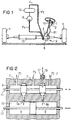
- An anti-theft device has a code transmitter, 1 (FIG. 1), which can be integrated, for example, on a door or ignition key.
- a code transmitter 1 FIG. 1
- FIG. 1 When a key of the code transmitter 1 is pressed, when the code transmitter 1 approaches the motor vehicle or when the ignition key is inserted and turned in the ignition lock 2, a code signal is transmitted.
- the code signal is received by a transmitting / receiving unit in the motor vehicle.
- the code signal is compared in a computing unit with a stored target code signal. If the code signal matches the target code signal, a control signal, i.e. generates an enable signal. This release signal is sent to a safety unit in the motor vehicle.
- the transmitting / receiving unit and the computing unit are located in a separate control unit which is connected to the safety unit via a bus, or — as shown in FIG. 1 — they are arranged in a control unit 3 that controls the safety unit.
- the steering device is such a safety unit.
- a user of the motor vehicle can only turn the vehicle wheels 4 when the release signal has been received by the steering device.
- the steering device can be a known power steering system, for example.
- the power steering helps the driver to steer so that only a small amount of effort is required to turn the steering wheel.
- a hydraulic power steering system is shown in FIG. 1 (see also FIG. 2).
- a hydraulic pump 6 allows the hydraulic fluid (hereinafter referred to as oil) to flow in a hydraulic circuit 7 under the pressure P V.
- oil the hydraulic fluid
- a servo valve 8 of the steering gear 9 the oil flow meets two valves which are actuated when the steering is turned in order to supply the double-acting actuating cylinder 10 with the oil under pressure P V.
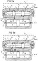
- the control piston 11 adjusts itself so that oil can increasingly reach the actuating cylinder 10, while at the same time the return line to the reservoir 12 increasingly opens (pressure P T ). As a result, the oil builds up in a chamber of the actuating cylinder 10 and pressure is exerted on the actuating piston 13, so that the actuating piston 13 can move and assist the driver in steering as desired.
- valves are actuated by means of a torsion bar in the steering gear 9 as a function of the respective steering forces.
- a torsion bar in the steering gear 9 as a function of the respective steering forces.
- both valve slides remain in a middle position.
- the servo valve 8 and the actuating cylinder are shown in FIG. 2 in a greatly simplified, illustrative form.
- the movement of the control piston 11 as a result of a steering wheel lock forces the actuating piston 13 to move, as a result of which the wheels 4 are steered.
- Oil is fed in under a pressure P V via a line.
- the return flow of the oil to the reservoir 12 takes place via one or more lines in which the pressure P T prevails. With the help of the hydraulic system, the effort required to steer is reduced.
- the release signal acts on the power steering so that the steering wheel can be turned.
- control piston 11 and, on the other hand, the actuating cylinder 10 can be fixed.
- the hydraulic circuit 7 can also be interrupted. Further possibilities are to hold the steering column 15 in place as with a brake.
- the power steering as a locking device can have a locking pin 16 which fixes the control piston 11 by locking it in an opening of the control piston 11.
- the locking bolt 16 is controlled hydraulically, electromotively, magnetically or pneumatically and is moved out of the recess in the control piston 11 (coils 17 are shown in the figure, via which the locking bolt 16 is moved electromechanically).
- the control piston 11 can be moved freely, as a result of which the adjusting piston 13 strikes the wheels 4.
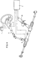
- the interruption of the hydraulic circuit 7 or an auxiliary circuit 7 ' is shown in more detail in FIG. 3a.
- the oil flows in the hydraulic circuit 7 and thus supports the driver. If the hydraulic circuit 7 is interrupted, the steering wheel cannot be turned.
- a locking device is provided in which a bolt 18 is pushed into the hydraulic circuit 7 or bolt 18 'into the auxiliary circuit 7', so that the oil flow is stopped.
- the auxiliary circuit 7 allows oil compensation between the two ends of the control piston 11. Since the control piston - contrary to the restoring forces by springs - moves to one side when steering, the oil located there must move via the auxiliary circuit 7' to the other end. If this auxiliary circuit 7 'is blocked, the steering is also no longer possible.
- the interruption of the hydraulic circuit 7, 7 ' can be achieved with minimal effort by electromotive, magnetic, pneumatic or similarly controlled movement of the bolt 18, 18' or by an electrical change in the hydraulic fluid, i.e. the viscosity.
- the viscosity of the oil is changed by an external electrical / magnetic field, so that the oil can no longer flow.
- Interrupting the hydraulic circuit 7 has the advantage that the steering can be locked in any steering position.
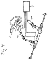
- the control unit 3 detects the desired angle of rotation of the steering wheel and converts this angle of rotation into a steering angle for the wheels 4 via an electric motor 20. If a release signal has not yet been received, the electric motor 20 is blocked via the control unit 3. As soon as the release signal is received via a code line 21 or a bus, the electric motor 20 is released and then controls the wheels 4 according to the driver's requirements.
- the locking device can be designed such that only an existing hydraulic pressure pushes the bolt 18 from the locked position into the open position.
- the latch 18 can, however, remain switchable, for example, electromechanically even when the hydraulic pressure is present.
- a by-pass line 22 is additionally provided, with the aid of which the Hydraulic circuit 7 is blocked against the hydraulic pressure of the oil.
- the pump 6 can also be released by the release signal.
- the pump 6 can also be operated in the opposite direction as long as no release signal has been received.
- the steering is blocked by the hydraulic flow in the opposite direction.
- the anti-theft device is only activated when the wheels are stationary. Because while driving, safety-critical situations could arise if the steering suddenly stops working.
- a further electric motor can also be provided, which acts directly on the steering column 15.
- the steering column 15 can then not be moved in the idle state. Only when the release signal has been received is the steering column 15 released to turn.
- the code transmitter 1 can be arranged in the form of a transponder on a door or ignition key. However, it can also be designed as remote control, which has a button and a transmitter via which the code signal is transmitted. A chip card or a keyboard permanently installed on the dashboard via which a code can be entered can also serve as the code transmitter 1.
- the code transmitter 1 is designed. It is only essential that a code signal is transmitted which is received by a control unit in the motor vehicle and evaluated there. The control unit therefore checks whether the code signal received is the target code signal matches. So-called authentication takes place.
- the code signal can be a fixed code, i.e. a constantly identical code signal is sent, or a change code or roll code, i.e. the code signal is changed after each transmission, act.
- the code signal and the target code signal can each be recalculated by a predetermined mathematical algorithm. Cryptographic methods can also be used.
- the control unit 3 in the motor vehicle can be designed as a separate control unit which sends the release signal to the control unit of the power steering.
- the control unit 3 can also be arranged integrated in the control unit of the power steering.
- the release signal can also be sent to other safety units in the motor vehicle, such as the engine control or the ignition device. This further increases the theft protection.
- the code signal can be transmitted from the code transmitter 1 to the control unit 3 wirelessly (optically, by radio or inductively) or galvanically via a line.
- the type of transmission is insignificant for the invention.
- Such an anti-theft device can replace the mechanical steering wheel lock. Because only when the correct code signal is received can the steering wheel be turned according to the invention.
Landscapes
- Engineering & Computer Science (AREA)
- Mechanical Engineering (AREA)
- Lock And Its Accessories (AREA)
Priority Applications (2)
| Application Number | Priority Date | Filing Date | Title |
|---|---|---|---|
| EP95100773A EP0722865B2 (fr) | 1995-01-20 | 1995-01-20 | Dispositif antivol pour un véhicule |
| DE59500565T DE59500565D1 (de) | 1995-01-20 | 1995-01-20 | Diebstahlschutzvorrichtung für ein Kraftfahrzeug |
Applications Claiming Priority (1)
| Application Number | Priority Date | Filing Date | Title |
|---|---|---|---|
| EP95100773A EP0722865B2 (fr) | 1995-01-20 | 1995-01-20 | Dispositif antivol pour un véhicule |
Publications (3)
| Publication Number | Publication Date |
|---|---|
| EP0722865A1 true EP0722865A1 (fr) | 1996-07-24 |
| EP0722865B1 EP0722865B1 (fr) | 1997-08-27 |
| EP0722865B2 EP0722865B2 (fr) | 2000-11-15 |
Family
ID=8218921
Family Applications (1)
| Application Number | Title | Priority Date | Filing Date |
|---|---|---|---|
| EP95100773A Expired - Lifetime EP0722865B2 (fr) | 1995-01-20 | 1995-01-20 | Dispositif antivol pour un véhicule |
Country Status (2)
| Country | Link |
|---|---|
| EP (1) | EP0722865B2 (fr) |
| DE (1) | DE59500565D1 (fr) |
Cited By (10)
| Publication number | Priority date | Publication date | Assignee | Title |
|---|---|---|---|---|
| GB2312657A (en) * | 1996-05-02 | 1997-11-05 | Daimler Benz Ag | Hydraulic servo steering system |
| DE19748326C1 (de) * | 1997-10-31 | 1999-05-12 | Siemens Ag | Diebstahlschutzvorrichtung für ein Kraftfahrzeug |
| DE19736651C1 (de) * | 1997-08-22 | 1999-08-12 | Siemens Ag | Diebstahlschutzvorrichtung für ein Kraftfahrzeug |
| DE19940323A1 (de) * | 1999-08-25 | 2001-03-01 | Opel Adam Ag | Kraftfahrzeug mit einer Lenkhilfe |
| EP0893315A3 (fr) * | 1997-07-23 | 2002-01-02 | Toyota Jidosha Kabushiki Kaisha | Système à clé électronique pour véhicules |
| EP1146259A3 (fr) * | 2000-04-15 | 2002-03-13 | Douglas Autotech Corp. | Verrouillage de commande de transmission |
| WO2002025143A1 (fr) * | 2000-09-20 | 2002-03-28 | Lord Corporation | Mecanisme et procede pour interverrouillage a commande de fluide |
| DE10158923A1 (de) * | 2001-11-30 | 2003-06-12 | Marquardt Gmbh | Lenkungseinrichtung für ein Kraftfahrzeug |
| DE102004020513A1 (de) * | 2004-04-26 | 2005-11-10 | Lämmle, Knud | Lenksperre |
| DE102009058612A1 (de) * | 2009-12-17 | 2011-06-22 | Volkswagen AG, 38440 | Elektromechanische Fahrzeuglenkung |
Citations (4)
| Publication number | Priority date | Publication date | Assignee | Title |
|---|---|---|---|---|
| EP0085383A1 (fr) * | 1982-01-28 | 1983-08-10 | Neiman S.A. | Antivol de direction à blocage hydraulique pour véhicules |
| EP0239987A2 (fr) * | 1986-04-02 | 1987-10-07 | Yehuda Baruch | Dispositif anti-vol pour véhicules |
| US4918955A (en) * | 1986-10-07 | 1990-04-24 | Kabushiki Kaisha Tokai Rika Denki Seisakusho | Vehicle key device |
| JPH03125651A (ja) * | 1989-10-11 | 1991-05-29 | Omron Corp | 車両の盗難防止装置 |
Family Cites Families (4)
| Publication number | Priority date | Publication date | Assignee | Title |
|---|---|---|---|---|
| DE3306863C2 (de) † | 1983-02-26 | 1986-07-03 | Daimler-Benz Ag, 7000 Stuttgart | Schloßsystem für Kraftfahrzeuge, insbesondere Lenkschloßsystem |
| DE3318359C2 (de) † | 1983-05-20 | 1985-11-21 | Hülsbeck & Fürst GmbH & Co KG, 5620 Velbert | Lenk- und Zündschloß für Kraftfahrzeuge |
| DE3739172C1 (en) † | 1987-11-19 | 1989-02-09 | Daimler Benz Ag | Locking system for motor vehicles |
| DE4314931A1 (de) † | 1993-05-06 | 1994-11-10 | Valeo Deutschland Gmbh & Co | Lenkschloß |
-
1995
- 1995-01-20 EP EP95100773A patent/EP0722865B2/fr not_active Expired - Lifetime
- 1995-01-20 DE DE59500565T patent/DE59500565D1/de not_active Expired - Fee Related
Patent Citations (4)
| Publication number | Priority date | Publication date | Assignee | Title |
|---|---|---|---|---|
| EP0085383A1 (fr) * | 1982-01-28 | 1983-08-10 | Neiman S.A. | Antivol de direction à blocage hydraulique pour véhicules |
| EP0239987A2 (fr) * | 1986-04-02 | 1987-10-07 | Yehuda Baruch | Dispositif anti-vol pour véhicules |
| US4918955A (en) * | 1986-10-07 | 1990-04-24 | Kabushiki Kaisha Tokai Rika Denki Seisakusho | Vehicle key device |
| JPH03125651A (ja) * | 1989-10-11 | 1991-05-29 | Omron Corp | 車両の盗難防止装置 |
Non-Patent Citations (1)
| Title |
|---|
| PATENT ABSTRACTS OF JAPAN vol. 15, no. 329 (M - 1149) 21 August 1991 (1991-08-21) * |
Cited By (13)
| Publication number | Priority date | Publication date | Assignee | Title |
|---|---|---|---|---|
| GB2312657B (en) * | 1996-05-02 | 1998-06-03 | Daimler Benz Ag | Hydraulic servo steering system |
| GB2312657A (en) * | 1996-05-02 | 1997-11-05 | Daimler Benz Ag | Hydraulic servo steering system |
| US6400254B2 (en) | 1997-07-23 | 2002-06-04 | Toyota Jidosha Kabushiki Kaisha | Vehicle electronic key system |
| EP0893315A3 (fr) * | 1997-07-23 | 2002-01-02 | Toyota Jidosha Kabushiki Kaisha | Système à clé électronique pour véhicules |
| DE19736651C1 (de) * | 1997-08-22 | 1999-08-12 | Siemens Ag | Diebstahlschutzvorrichtung für ein Kraftfahrzeug |
| DE19748326C1 (de) * | 1997-10-31 | 1999-05-12 | Siemens Ag | Diebstahlschutzvorrichtung für ein Kraftfahrzeug |
| DE19940323A1 (de) * | 1999-08-25 | 2001-03-01 | Opel Adam Ag | Kraftfahrzeug mit einer Lenkhilfe |
| EP1146259A3 (fr) * | 2000-04-15 | 2002-03-13 | Douglas Autotech Corp. | Verrouillage de commande de transmission |
| WO2002025143A1 (fr) * | 2000-09-20 | 2002-03-28 | Lord Corporation | Mecanisme et procede pour interverrouillage a commande de fluide |
| DE10158923A1 (de) * | 2001-11-30 | 2003-06-12 | Marquardt Gmbh | Lenkungseinrichtung für ein Kraftfahrzeug |
| DE102004020513A1 (de) * | 2004-04-26 | 2005-11-10 | Lämmle, Knud | Lenksperre |
| DE102009058612A1 (de) * | 2009-12-17 | 2011-06-22 | Volkswagen AG, 38440 | Elektromechanische Fahrzeuglenkung |
| DE102009058612B4 (de) | 2009-12-17 | 2022-05-19 | Volkswagen Aktiengesellschaft | Elektromechanische Fahrzeuglenkung |
Also Published As
| Publication number | Publication date |
|---|---|
| EP0722865B2 (fr) | 2000-11-15 |
| DE59500565D1 (de) | 1997-10-02 |
| EP0722865B1 (fr) | 1997-08-27 |
Similar Documents
| Publication | Publication Date | Title |
|---|---|---|
| EP2700545B1 (fr) | Procédé de fonctionnement d'un système de commande d'une moto | |
| EP0722865B1 (fr) | Dispositif antivol pour un véhicule | |
| EP1135284B1 (fr) | Systeme de fermeture, notamment pour automobiles | |
| EP0846602B1 (fr) | Dispositif de commande pour au moins un verrou de blockage et son utilisation dans un antivol de direction pour automobile | |
| DE102006056042A1 (de) | System zur Verriegelung und Freigabe einer elektromechanischen Lenkung | |
| DE19957624C2 (de) | Elektronisches Lenkschloß und elektronischer Zündanlaßschalter für Kraftfahrzeuge | |
| DE4427267C2 (de) | Diebstahlsicherung für ein Kraftfahrzeug | |
| EP1029756B1 (fr) | Système de serrure d'allumage électronique pour un véhicule à moteur | |
| EP0721869B1 (fr) | Dispositif de verrouillage pour véhicules | |
| DE19960958B4 (de) | Vorrichtung zum Diebstahlschutz | |
| DE10107992B4 (de) | Zündschloßsystem für ein Kraftfahrzeug | |
| DE19860350C5 (de) | Schlüssellose Motorstartberechtigungskontrolleinrichung | |
| WO2002027123A1 (fr) | Serrure de contact pour un vehicule automobile | |
| EP1121278B1 (fr) | Dispositif de commande pour l'allumage et le blocage de la direction d'une automobile | |
| DE102006035803A1 (de) | Kraftfahrzeug, insbesondere Schließsystem für ein Kraftfahrzeug | |
| DE4498428B4 (de) | Diebstahlsicherung für Kraftfahrzeuge mit Getriebe oder derartiges Getriebe | |
| DE10206786B4 (de) | Bremsvorrichtung für ein Kraftfahrzeug | |
| DE4108507A1 (de) | Kraftfahrzeugtuerverschluss mit zentralverriegelungsantrieb | |
| DE10393313B4 (de) | Diebstahlsicherungsvorrichtung für Kraftfahrzeuge mit hydraulischer Servolenkung | |
| DE102006049419A1 (de) | Kraftfahrzeug mit einem Fahrberechtigungssystem und einem elektronisch steuerbaren Parkbremssystem sowie Verfahren zu dessen Betrieb | |
| DE4223529A1 (de) | Kraftfahrzeug-Diebstahlsicherung | |
| EP1029757A2 (fr) | Interrupteur d'allumage actionné manuellement pour un dispositif de contrôle d'autorisation sans clé du démarrage d'un véhicule à moteur | |
| EP0732241A2 (fr) | Dispositif de verrouillage pour véhicules | |
| DE10310294B4 (de) | Vorrichtung zur Ansteuerung einer elektrischen Sicherungseinrichtung für ein Kraftfahrzeug | |
| DE10158923A1 (de) | Lenkungseinrichtung für ein Kraftfahrzeug |
Legal Events
| Date | Code | Title | Description |
|---|---|---|---|
| PUAI | Public reference made under article 153(3) epc to a published international application that has entered the european phase |
Free format text: ORIGINAL CODE: 0009012 |
|
| AK | Designated contracting states |
Kind code of ref document: A1 Designated state(s): DE FR GB |
|
| 17P | Request for examination filed |
Effective date: 19960806 |
|
| RBV | Designated contracting states (corrected) |
Designated state(s): DE FR GB |
|
| GRAG | Despatch of communication of intention to grant |
Free format text: ORIGINAL CODE: EPIDOS AGRA |
|
| GRAH | Despatch of communication of intention to grant a patent |
Free format text: ORIGINAL CODE: EPIDOS IGRA |
|
| 17Q | First examination report despatched |
Effective date: 19970213 |
|
| GRAH | Despatch of communication of intention to grant a patent |
Free format text: ORIGINAL CODE: EPIDOS IGRA |
|
| GRAA | (expected) grant |
Free format text: ORIGINAL CODE: 0009210 |
|
| AK | Designated contracting states |
Kind code of ref document: B1 Designated state(s): DE FR GB |
|
| REF | Corresponds to: |
Ref document number: 59500565 Country of ref document: DE Date of ref document: 19971002 |
|
| ET | Fr: translation filed | ||
| GBT | Gb: translation of ep patent filed (gb section 77(6)(a)/1977) |
Effective date: 19971103 |
|
| PLBQ | Unpublished change to opponent data |
Free format text: ORIGINAL CODE: EPIDOS OPPO |
|
| PLBI | Opposition filed |
Free format text: ORIGINAL CODE: 0009260 |
|
| PLBF | Reply of patent proprietor to notice(s) of opposition |
Free format text: ORIGINAL CODE: EPIDOS OBSO |
|
| 26 | Opposition filed |
Opponent name: VALEO GMBH & CO. SCHLIESS-SYSTEME KG Effective date: 19980527 |
|
| PLBF | Reply of patent proprietor to notice(s) of opposition |
Free format text: ORIGINAL CODE: EPIDOS OBSO |
|
| PLAW | Interlocutory decision in opposition |
Free format text: ORIGINAL CODE: EPIDOS IDOP |
|
| PLAW | Interlocutory decision in opposition |
Free format text: ORIGINAL CODE: EPIDOS IDOP |
|
| PUAH | Patent maintained in amended form |
Free format text: ORIGINAL CODE: 0009272 |
|
| STAA | Information on the status of an ep patent application or granted ep patent |
Free format text: STATUS: PATENT MAINTAINED AS AMENDED |
|
| 27A | Patent maintained in amended form |
Effective date: 20001115 |
|
| AK | Designated contracting states |
Kind code of ref document: B2 Designated state(s): DE FR GB |
|
| ET3 | Fr: translation filed ** decision concerning opposition | ||
| GBTA | Gb: translation of amended ep patent filed (gb section 77(6)(b)/1977) | ||
| REG | Reference to a national code |
Ref country code: GB Ref legal event code: IF02 |
|
| PGFP | Annual fee paid to national office [announced via postgrant information from national office to epo] |
Ref country code: GB Payment date: 20030114 Year of fee payment: 9 |
|
| PGFP | Annual fee paid to national office [announced via postgrant information from national office to epo] |
Ref country code: FR Payment date: 20030124 Year of fee payment: 9 |
|
| PGFP | Annual fee paid to national office [announced via postgrant information from national office to epo] |
Ref country code: DE Payment date: 20030317 Year of fee payment: 9 |
|
| PG25 | Lapsed in a contracting state [announced via postgrant information from national office to epo] |
Ref country code: GB Free format text: LAPSE BECAUSE OF NON-PAYMENT OF DUE FEES Effective date: 20040120 |
|
| PG25 | Lapsed in a contracting state [announced via postgrant information from national office to epo] |
Ref country code: DE Free format text: LAPSE BECAUSE OF NON-PAYMENT OF DUE FEES Effective date: 20040803 |
|
| GBPC | Gb: european patent ceased through non-payment of renewal fee |
Effective date: 20040120 |
|
| PG25 | Lapsed in a contracting state [announced via postgrant information from national office to epo] |
Ref country code: FR Free format text: LAPSE BECAUSE OF NON-PAYMENT OF DUE FEES Effective date: 20040930 |
|
| REG | Reference to a national code |
Ref country code: FR Ref legal event code: ST |
|
| PLAB | Opposition data, opponent's data or that of the opponent's representative modified |
Free format text: ORIGINAL CODE: 0009299OPPO |