EP0724290A2 - Boîtier électronique - Google Patents
Boîtier électronique Download PDFInfo
- Publication number
- EP0724290A2 EP0724290A2 EP19960100261 EP96100261A EP0724290A2 EP 0724290 A2 EP0724290 A2 EP 0724290A2 EP 19960100261 EP19960100261 EP 19960100261 EP 96100261 A EP96100261 A EP 96100261A EP 0724290 A2 EP0724290 A2 EP 0724290A2
- Authority
- EP
- European Patent Office
- Prior art keywords
- package
- electrical circuitry
- circuitry
- density
- thin dielectric
- Prior art date
- Legal status (The legal status is an assumption and is not a legal conclusion. Google has not performed a legal analysis and makes no representation as to the accuracy of the status listed.)
- Withdrawn
Links
Images


Classifications
-
- H—ELECTRICITY
- H10—SEMICONDUCTOR DEVICES; ELECTRIC SOLID-STATE DEVICES NOT OTHERWISE PROVIDED FOR
- H10W—GENERIC PACKAGES, INTERCONNECTIONS, CONNECTORS OR OTHER CONSTRUCTIONAL DETAILS OF DEVICES COVERED BY CLASS H10
- H10W72/00—Interconnections or connectors in packages
-
- H—ELECTRICITY
- H10—SEMICONDUCTOR DEVICES; ELECTRIC SOLID-STATE DEVICES NOT OTHERWISE PROVIDED FOR
- H10W—GENERIC PACKAGES, INTERCONNECTIONS, CONNECTORS OR OTHER CONSTRUCTIONAL DETAILS OF DEVICES COVERED BY CLASS H10
- H10W70/00—Package substrates; Interposers; Redistribution layers [RDL]
- H10W70/60—Insulating or insulated package substrates; Interposers; Redistribution layers
- H10W70/611—Insulating or insulated package substrates; Interposers; Redistribution layers for connecting multiple chips together
-
- H—ELECTRICITY
- H10—SEMICONDUCTOR DEVICES; ELECTRIC SOLID-STATE DEVICES NOT OTHERWISE PROVIDED FOR
- H10W—GENERIC PACKAGES, INTERCONNECTIONS, CONNECTORS OR OTHER CONSTRUCTIONAL DETAILS OF DEVICES COVERED BY CLASS H10
- H10W70/00—Package substrates; Interposers; Redistribution layers [RDL]
- H10W70/60—Insulating or insulated package substrates; Interposers; Redistribution layers
- H10W70/67—Insulating or insulated package substrates; Interposers; Redistribution layers characterised by their insulating layers or insulating parts
- H10W70/68—Shapes or dispositions thereof
- H10W70/685—Shapes or dispositions thereof comprising multiple insulating layers
-
- H—ELECTRICITY
- H10—SEMICONDUCTOR DEVICES; ELECTRIC SOLID-STATE DEVICES NOT OTHERWISE PROVIDED FOR
- H10W—GENERIC PACKAGES, INTERCONNECTIONS, CONNECTORS OR OTHER CONSTRUCTIONAL DETAILS OF DEVICES COVERED BY CLASS H10
- H10W70/00—Package substrates; Interposers; Redistribution layers [RDL]
- H10W70/60—Insulating or insulated package substrates; Interposers; Redistribution layers
- H10W70/67—Insulating or insulated package substrates; Interposers; Redistribution layers characterised by their insulating layers or insulating parts
- H10W70/68—Shapes or dispositions thereof
- H10W70/6875—Shapes or dispositions thereof being on a metallic substrate, e.g. insulated metal substrates [IMS]
-
- H—ELECTRICITY
- H10—SEMICONDUCTOR DEVICES; ELECTRIC SOLID-STATE DEVICES NOT OTHERWISE PROVIDED FOR
- H10W—GENERIC PACKAGES, INTERCONNECTIONS, CONNECTORS OR OTHER CONSTRUCTIONAL DETAILS OF DEVICES COVERED BY CLASS H10
- H10W74/00—Encapsulations, e.g. protective coatings
- H10W74/01—Manufacture or treatment
- H10W74/012—Manufacture or treatment of encapsulations on active surfaces of flip-chip devices, e.g. forming underfills
-
- H—ELECTRICITY
- H10—SEMICONDUCTOR DEVICES; ELECTRIC SOLID-STATE DEVICES NOT OTHERWISE PROVIDED FOR
- H10W—GENERIC PACKAGES, INTERCONNECTIONS, CONNECTORS OR OTHER CONSTRUCTIONAL DETAILS OF DEVICES COVERED BY CLASS H10
- H10W74/00—Encapsulations, e.g. protective coatings
- H10W74/10—Encapsulations, e.g. protective coatings characterised by their shape or disposition
- H10W74/111—Encapsulations, e.g. protective coatings characterised by their shape or disposition the semiconductor body being completely enclosed
- H10W74/114—Encapsulations, e.g. protective coatings characterised by their shape or disposition the semiconductor body being completely enclosed by a substrate and the encapsulations
-
- H—ELECTRICITY
- H10—SEMICONDUCTOR DEVICES; ELECTRIC SOLID-STATE DEVICES NOT OTHERWISE PROVIDED FOR
- H10W—GENERIC PACKAGES, INTERCONNECTIONS, CONNECTORS OR OTHER CONSTRUCTIONAL DETAILS OF DEVICES COVERED BY CLASS H10
- H10W74/00—Encapsulations, e.g. protective coatings
- H10W74/10—Encapsulations, e.g. protective coatings characterised by their shape or disposition
- H10W74/15—Encapsulations, e.g. protective coatings characterised by their shape or disposition on active surfaces of flip-chip devices, e.g. underfills
-
- H—ELECTRICITY
- H10—SEMICONDUCTOR DEVICES; ELECTRIC SOLID-STATE DEVICES NOT OTHERWISE PROVIDED FOR
- H10W—GENERIC PACKAGES, INTERCONNECTIONS, CONNECTORS OR OTHER CONSTRUCTIONAL DETAILS OF DEVICES COVERED BY CLASS H10
- H10W74/00—Encapsulations, e.g. protective coatings
- H10W74/40—Encapsulations, e.g. protective coatings characterised by their materials
- H10W74/47—Encapsulations, e.g. protective coatings characterised by their materials comprising organic materials, e.g. plastics or resins
-
- H—ELECTRICITY
- H10—SEMICONDUCTOR DEVICES; ELECTRIC SOLID-STATE DEVICES NOT OTHERWISE PROVIDED FOR
- H10W—GENERIC PACKAGES, INTERCONNECTIONS, CONNECTORS OR OTHER CONSTRUCTIONAL DETAILS OF DEVICES COVERED BY CLASS H10
- H10W90/00—Package configurations
- H10W90/401—Package configurations characterised by multiple insulating or insulated package substrates, interposers or RDLs
-
- H—ELECTRICITY
- H10—SEMICONDUCTOR DEVICES; ELECTRIC SOLID-STATE DEVICES NOT OTHERWISE PROVIDED FOR
- H10W—GENERIC PACKAGES, INTERCONNECTIONS, CONNECTORS OR OTHER CONSTRUCTIONAL DETAILS OF DEVICES COVERED BY CLASS H10
- H10W90/00—Package configurations
- H10W90/701—Package configurations characterised by the relative positions of pads or connectors relative to package parts
-
- H—ELECTRICITY
- H10—SEMICONDUCTOR DEVICES; ELECTRIC SOLID-STATE DEVICES NOT OTHERWISE PROVIDED FOR
- H10H—INORGANIC LIGHT-EMITTING SEMICONDUCTOR DEVICES HAVING POTENTIAL BARRIERS
- H10H20/00—Individual inorganic light-emitting semiconductor devices having potential barriers, e.g. light-emitting diodes [LED]
- H10H20/80—Constructional details
- H10H20/85—Packages
- H10H20/857—Interconnections, e.g. lead-frames, bond wires or solder balls
-
- H—ELECTRICITY
- H10—SEMICONDUCTOR DEVICES; ELECTRIC SOLID-STATE DEVICES NOT OTHERWISE PROVIDED FOR
- H10W—GENERIC PACKAGES, INTERCONNECTIONS, CONNECTORS OR OTHER CONSTRUCTIONAL DETAILS OF DEVICES COVERED BY CLASS H10
- H10W70/00—Package substrates; Interposers; Redistribution layers [RDL]
- H10W70/60—Insulating or insulated package substrates; Interposers; Redistribution layers
- H10W70/62—Insulating or insulated package substrates; Interposers; Redistribution layers characterised by their interconnections
- H10W70/63—Vias, e.g. via plugs
-
- H—ELECTRICITY
- H10—SEMICONDUCTOR DEVICES; ELECTRIC SOLID-STATE DEVICES NOT OTHERWISE PROVIDED FOR
- H10W—GENERIC PACKAGES, INTERCONNECTIONS, CONNECTORS OR OTHER CONSTRUCTIONAL DETAILS OF DEVICES COVERED BY CLASS H10
- H10W70/00—Package substrates; Interposers; Redistribution layers [RDL]
- H10W70/60—Insulating or insulated package substrates; Interposers; Redistribution layers
- H10W70/67—Insulating or insulated package substrates; Interposers; Redistribution layers characterised by their insulating layers or insulating parts
- H10W70/68—Shapes or dispositions thereof
- H10W70/682—Shapes or dispositions thereof comprising holes having chips therein
-
- H—ELECTRICITY
- H10—SEMICONDUCTOR DEVICES; ELECTRIC SOLID-STATE DEVICES NOT OTHERWISE PROVIDED FOR
- H10W—GENERIC PACKAGES, INTERCONNECTIONS, CONNECTORS OR OTHER CONSTRUCTIONAL DETAILS OF DEVICES COVERED BY CLASS H10
- H10W72/00—Interconnections or connectors in packages
- H10W72/01—Manufacture or treatment
- H10W72/013—Manufacture or treatment of die-attach connectors
- H10W72/01308—Manufacture or treatment of die-attach connectors using permanent auxiliary members, e.g. using alignment marks
-
- H—ELECTRICITY
- H10—SEMICONDUCTOR DEVICES; ELECTRIC SOLID-STATE DEVICES NOT OTHERWISE PROVIDED FOR
- H10W—GENERIC PACKAGES, INTERCONNECTIONS, CONNECTORS OR OTHER CONSTRUCTIONAL DETAILS OF DEVICES COVERED BY CLASS H10
- H10W72/00—Interconnections or connectors in packages
- H10W72/071—Connecting or disconnecting
- H10W72/073—Connecting or disconnecting of die-attach connectors
- H10W72/07311—Treating the bonding area before connecting, e.g. by applying flux or cleaning
-
- H—ELECTRICITY
- H10—SEMICONDUCTOR DEVICES; ELECTRIC SOLID-STATE DEVICES NOT OTHERWISE PROVIDED FOR
- H10W—GENERIC PACKAGES, INTERCONNECTIONS, CONNECTORS OR OTHER CONSTRUCTIONAL DETAILS OF DEVICES COVERED BY CLASS H10
- H10W72/00—Interconnections or connectors in packages
- H10W72/50—Bond wires
- H10W72/551—Materials of bond wires
- H10W72/552—Materials of bond wires comprising metals or metalloids, e.g. silver
- H10W72/5522—Materials of bond wires comprising metals or metalloids, e.g. silver comprising gold [Au]
-
- H—ELECTRICITY
- H10—SEMICONDUCTOR DEVICES; ELECTRIC SOLID-STATE DEVICES NOT OTHERWISE PROVIDED FOR
- H10W—GENERIC PACKAGES, INTERCONNECTIONS, CONNECTORS OR OTHER CONSTRUCTIONAL DETAILS OF DEVICES COVERED BY CLASS H10
- H10W72/00—Interconnections or connectors in packages
- H10W72/851—Dispositions of multiple connectors or interconnections
- H10W72/853—On the same surface
- H10W72/856—Bump connectors and die-attach connectors
-
- H—ELECTRICITY
- H10—SEMICONDUCTOR DEVICES; ELECTRIC SOLID-STATE DEVICES NOT OTHERWISE PROVIDED FOR
- H10W—GENERIC PACKAGES, INTERCONNECTIONS, CONNECTORS OR OTHER CONSTRUCTIONAL DETAILS OF DEVICES COVERED BY CLASS H10
- H10W72/00—Interconnections or connectors in packages
- H10W72/851—Dispositions of multiple connectors or interconnections
- H10W72/874—On different surfaces
- H10W72/884—Die-attach connectors and bond wires
-
- H—ELECTRICITY
- H10—SEMICONDUCTOR DEVICES; ELECTRIC SOLID-STATE DEVICES NOT OTHERWISE PROVIDED FOR
- H10W—GENERIC PACKAGES, INTERCONNECTIONS, CONNECTORS OR OTHER CONSTRUCTIONAL DETAILS OF DEVICES COVERED BY CLASS H10
- H10W74/00—Encapsulations, e.g. protective coatings
-
- H—ELECTRICITY
- H10—SEMICONDUCTOR DEVICES; ELECTRIC SOLID-STATE DEVICES NOT OTHERWISE PROVIDED FOR
- H10W—GENERIC PACKAGES, INTERCONNECTIONS, CONNECTORS OR OTHER CONSTRUCTIONAL DETAILS OF DEVICES COVERED BY CLASS H10
- H10W90/00—Package configurations
- H10W90/701—Package configurations characterised by the relative positions of pads or connectors relative to package parts
- H10W90/721—Package configurations characterised by the relative positions of pads or connectors relative to package parts of bump connectors
- H10W90/724—Package configurations characterised by the relative positions of pads or connectors relative to package parts of bump connectors between a chip and a stacked insulating package substrate, interposer or RDL
-
- H—ELECTRICITY
- H10—SEMICONDUCTOR DEVICES; ELECTRIC SOLID-STATE DEVICES NOT OTHERWISE PROVIDED FOR
- H10W—GENERIC PACKAGES, INTERCONNECTIONS, CONNECTORS OR OTHER CONSTRUCTIONAL DETAILS OF DEVICES COVERED BY CLASS H10
- H10W90/00—Package configurations
- H10W90/701—Package configurations characterised by the relative positions of pads or connectors relative to package parts
- H10W90/731—Package configurations characterised by the relative positions of pads or connectors relative to package parts of die-attach connectors
- H10W90/734—Package configurations characterised by the relative positions of pads or connectors relative to package parts of die-attach connectors between a chip and a stacked insulating package substrate, interposer or RDL
-
- H—ELECTRICITY
- H10—SEMICONDUCTOR DEVICES; ELECTRIC SOLID-STATE DEVICES NOT OTHERWISE PROVIDED FOR
- H10W—GENERIC PACKAGES, INTERCONNECTIONS, CONNECTORS OR OTHER CONSTRUCTIONAL DETAILS OF DEVICES COVERED BY CLASS H10
- H10W90/00—Package configurations
- H10W90/701—Package configurations characterised by the relative positions of pads or connectors relative to package parts
- H10W90/731—Package configurations characterised by the relative positions of pads or connectors relative to package parts of die-attach connectors
- H10W90/736—Package configurations characterised by the relative positions of pads or connectors relative to package parts of die-attach connectors between a chip and a stacked lead frame, conducting package substrate or heat sink
-
- H—ELECTRICITY
- H10—SEMICONDUCTOR DEVICES; ELECTRIC SOLID-STATE DEVICES NOT OTHERWISE PROVIDED FOR
- H10W—GENERIC PACKAGES, INTERCONNECTIONS, CONNECTORS OR OTHER CONSTRUCTIONAL DETAILS OF DEVICES COVERED BY CLASS H10
- H10W90/00—Package configurations
- H10W90/701—Package configurations characterised by the relative positions of pads or connectors relative to package parts
- H10W90/751—Package configurations characterised by the relative positions of pads or connectors relative to package parts of bond wires
- H10W90/754—Package configurations characterised by the relative positions of pads or connectors relative to package parts of bond wires between a chip and a stacked insulating package substrate, interposer or RDL
Definitions
- the invention relates to electronic packages and particularly to such packages which utilize at least one semiconductor device (chip) as part thereof.
- Electronic packages of the type described above, and particularly those which are especially adapted for use in information handling systems (computers), are well known in the art.
- these packages include some type of substrate (e.g., ceramic or fiberglass-reinforced epoxy) with the semiconductor chip electrically coupled thereto.
- wirebonding a plurality of gold wires interconnect contact sites on the chip to respective conductors on the substrate
- thermocompression bonding where heat and pressure is applied to bond two elements, e.g., projecting leads from a thin film flexible circuit and the respective chip contact sites, to thereby form an interdiffusion bond between these elements along a common interface
- soldering wherein solder elements, e.g., spherical balls, are used to couple the chip's contact sites directly to the substrate's conductors or to leads on an interim thin film flexible circuit which is then electrically coupled to the substrate).
- sputtering In the manufacture of electronic packages, one known and accepted process used to provide the metallic portions which will eventually form part of the electrical circuitry is sputtering, wherein ions from a plasma bombard a "source", e.g., copper plate, such that atoms removed from the source are deposited onto the substrate base material, e.g., a thin polyimide layer located on a ceramic base.
- a substrate base material e.g., a thin polyimide layer located on a ceramic base.
- an interim metal e.g., chromium
- This chromium designed primarily for providing increased adhesion of the copper, is also preferably sputtered.
- a second layer of chromium may also be deposited onto the deposited copper, also preferably using a sputtering operation.
- Sputtering is particularly desirable as a manufacturing process for forming electrical circuitry because of the ability to form extremely thin, uniform lines and pads of high density.
- high density as used herein is understood to mean, with respect to circuit lines, the number of lines on the substrate's surface per linear inch, and, with respect to conductor pads or sites, the respective diameters or widths of the pads and the center-to center spacing between such pads.
- the substrate material must be capable of withstanding such temperatures.
- Acceptable materials for such substrates have included, primarily, ceramics and the like, whereas materials such as fiberglass-reinforced epoxies (also known in the industry as FR4) are not considered acceptable due to the inability thereof to accept such increased temperatures, e.g., sometimes in excess of 400° Celsius (C), at typical mass production rates.
- Sputtering is an accepted process in the production of known packages using a ceramic substrate with a thin polyimide layer thereon (a thin layer of polyimide is capable of withstanding high production temperatures) and the circuitry formed on the polyimide, the resulting packages known as multilayered ceramic packages (MCPs).
- MCPs multilayered ceramic packages
- Provision of both substrate and PCB with substantially similar CTEs significantly reduces stresses that may occur at the interface between these two members resulting from application of heat to the interface (e.g., to effect solder reflow). Understandably, significantly different rates of expansion at this location of the package could damage solder or similar type connections, and possibly render the package inoperative.
- an electronic package adapted for being electrically coupled to an electronic substrate, e.g., PCB
- the package comprises a thermally conductive member, a thin dielectric layer of organic material positioned on the thermally conductive member, at least one layer of electrical circuitry positioned on the thin dielectric layer and including a first portion having a first circuit density and a second portion including a second circuit density less than the first density, a semiconductor device positioned relative to the first portion of the electrical circuitry and electrically coupled to the first portion, and a plurality of electrically conductive members positioned in a predetermined pattern relative to the second portion of the electrical circuitry and electrically coupled to the second portion.
- the electrically conductive members are adapted for being electrically coupled to the electronic structure when the electronic package is positioned on the structure.
- an electronic package assembly comprising a thermally conductive member, a thin dielectric layer of organic material positioned on the thermally conductive member, at least one layer of electrical circuitry positioned on the thin dielectric layer and including a first portion having a first circuit density and a second portion including a second circuit density less than the first density, a semiconductor device positioned relative to the first portion of the electrical circuitry and electrically coupled to the first portion, a plurality of electrically conductive members positioned in a predetermined pattern relative to the second portion of the electrical circuitry and electrically coupled to the second portion, and an electronic structure including a plurality of conductors, selected ones of the electrically conductive members being electrically coupled to respective ones of the conductors.
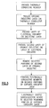
- a method for making an electronic package comprising the steps of providing a thermally conductive member, providing a thin dielectric layer of organic material on the thermally conductive member, providing a layer of electrical circuitry on the thin dielectric layer wherein the circuitry includes a first portion having a first circuit density and a second portion having a second circuitry density less than the first density, electrically coupling a semiconductor device to the first portion of the electrical circuitry, and electrically coupling a plurality of electrically conductive members to the second portion of the electrical circuitry.
- FIG. 1 there is shown an electronic package 10 in accordance with one embodiment of the invention.
- Package 10 includes a thermally conductive, substantially planar member 11, which, in a preferred embodiment, is comprised of copper or aluminum or alloys thereof.
- Member 11 may assume at least two configurations, depending on the chosen approach for coupling the invention's semiconductor device (chip) 13 (13' in FIG. 2) to the invention's conductive circuitry (defined below).
- Member 11 is preferably provided in much larger size relative to the chip than partially shown in FIGS. 1 and 2 such that several (e.g., twelve) packages each including one chip 13 (or 13') can be produced in a simultaneous manner. This feature is considered particularly significant regarding packages of this type and of course contributes substantially to reducing the overall costs of each final package.
- a rectangular copper sheet having a thickness of about 0.64 cms (centimeters) and side and length dimensions of 9.10 cms by 12.70 cms can be provided, so as to produce the aforementioned twelve single chip packages such as package 10 therefrom.
- the sheet, having all chips (and circuitry and other elements, as explained below) positioned thereon and electrically coupled to respective circuitry, can then be cut (divided) into individual package structures, each having substantially rectangular configurations with side and length dimensions of 2.70 cms and 2.90 cms, respectively.
- Each such structure is not limited to only a singular chip, it being readily possible to have a greater number of chips per package, using the teachings herein.
- Package 10 is designed for being mounted on and electrically coupled to an electronic structure such as a printed circuit board (PCB) 15, to thereby form a larger electronic package assembly.
- Package 10 in such mounted form may possess a height of only about 0.15 cms above the upper surface of the board, to thereby present a thin, low profile on board 15. Understandably, such a feature contributes significantly to miniaturization efforts with respect to such packages.
- Member 11 serves as a stiffener for package 10 and, if desired, may also serve as either a floating or coupled ground plane. Further description will be provided below.
- the invention assures a substantial match in CTEs between the member 11 and corresponding structure (PCB 15) on which package 10 is positioned and electrically coupled. This represents a significant feature of the invention because it serves to substantially reduce the occurrence of relatively high stresses at the bond locations between package and PCB.
- such bond locations involve the use of electrically conductive members 25 which, in a preferred embodiment, are solder balls.
- a preferred solder for members 25 is 10:90 tin:lead solder, a known solder material in the packaging art. Understandably, similar CTEs between member 11 and board 15 significantly reduces stresses on the solder balls 25 during package operation and/or assembly (wherein heat is often applied, e.g., to reflow various solder structures).
- member 11 includes a thin layer of metal 17 on opposite surfaces thereof. (This is also shown for the embodiment in FIG. 2).
- chromium is the metal for this layer and is deposited preferably using electroplating.
- layers 17 each may possess a thickness of about 0.20 mils. (A mil is understood to comprise one one/thousandth of an inch.)
- dielectric layer 19 of organic material is applied onto the chromium layer 17 along the undersurface of member 11.
- dielectric layer 19 is polyimide and is applied using a spraying operation. The polyimide thickness is only 0.30 mils. After spraying, the material is dried for about 15 minutes at 100°C. The material is then cured at 365°C for several hours.
- Thin dielectric layer 19 will serve as a base layer on which the invention's single layer of circuitry is provided.
- This circuitry represented by the numeral 21 in FIGS. 1 and 2, is comprised initially of chromium-copper-chromium and it is deposited atop layer 19 using a known sputtering process, such as described above. In this process, the three layers of metal are applied sequentially in a single vacuum operation. Typical thicknesses are 800 Angstroms of chromium, 80,000 Angstroms of copper and 800 Angstroms of chromium.
- circuitry 21 is shown to include a plurality of relatively small conductors 23 at the portion of circuitry 21 adjacent chip 13, and substantially wider conductors 24 at the relatively extreme right and left sides of the package as seen in FIG. 1.
- circuitry 21, on both the FIG. 1 and FIG. 2 embodiments comprises a first portion having a first circuit density and a second portion having a second, lesser density than that of the circuitry's first portion.
- this first portion of higher density includes conductors 23 which, as shown, are designed for being directly coupled to chip 13 using an interim array of solder elements 27.
- the conductors 24 located at the outer portions of the layer of circuitry 21 are shown to be somewhat wider than conductors 23.
- These conductors, while of a substantially similar thickness and provided simultaneously with the remainder (conductors 23) of circuitry 21, are of a lesser circuit density than that portion of the circuitry possessing the more closely spaced conductors 23.
- the conductors 23 in this first portion of circuitry 21 comprised a grouping of pads and were of substantially cylindrical configuration possessing a diameter of only about 3.5 mils. These pad conductors were spaced at an average distance from one another (pitch) at about 9 mils (center-to-center). In comparison, the associated pads 24 located at the outer portions of circuitry 21 were also of substantially cylindrical configuration and each possessed a diameter of about 16 mils. The desired pitch (center-to-center) of these conductors was about 50 mils. Should the first portion of circuitry possessing conductors 23 be comprised of lines and not pads, it is preferred that this density be from about 500 to 600 lines per inch.
- each line possesses a width of about 0.7 mils and the lines are spaced apart on 1.80 mil center-to-center spacings.
- lines also be utilized for the outer, lower density portion of circuitry 21, such lines would occupy a density of about fifty to one-hundred lines per inch. It is preferred, however, to provide pads (rectangular or cylindrical) at the circuit's outer portions because of the need to electrically couple these elements to the substantially larger solder conductive members 25.
- chip 13 includes a plurality of contact sites (not shown) which are each electrically coupled to a respective conductor 23 (or to a common conductor, e.g., ground) using the illustrated solder elements 27.
- solder elements 27 were of spherical ball configuration and comprised of 3:97 tin:lead solder.
- a preferred procedure for providing coupling between the chip and circuitry is a solder reflow operation wherein the package (member 11 with chip 13 in position) is placed in an oven at a temperature of about 350°C for a period of about 5 minutes.
- each hole was of substantially cylindrical configuration and possessed a diameter of only about 17 mils.
- the second layer of organic material 31 may be applied across the entire upper surface of circuitry 21. This occurs, of course, after the formation of the circuit pattern for the circuitry.
- this pattern including the inner, more dense circuit regions and the outer, less dense regions, is accomplished using known photolithography procedures. During such procedures, a photoresist material (not shown) is deposited, exposed (to expose a pattern), developed and baked. The circuit pattern is formed by etching away the exposed metal. The remaining photoresist, which protected the metal that now constitutes the circuit pattern, is then removed leaving the respective circuit elements (e.g., 23, 24) exposed.
- the desired pads on which the larger solder ball members 25 and the much smaller solder ball elements 27 are to be coupled, are then exposed using the aforementioned laser ablation process.
- laser ablation is capable of providing very small diameter openings in such organic material as polyimide.
- the openings provided for conductors 23 into which the smaller solder elements 27 are positioned each possessed a diameter of only about 5 mils. It is noted in FIG. 1 that material 31 is not shown directly under chip 13 for illustration purposes.
- the circuitry exposed as a result of such removal is now subjected to an etch process in which the upper chromium is removed, thereby exposing the underlying copper. It is to this copper that the solder members in FIG. 1 are directly coupled.
- the larger solder ball members 25 are coupled to the respective pads, or lines 24. If a series of packages have been simultaneously provided through the provision of a large thermally conductive member 11 and several additional chip sites and outer lead sites for each package thereon, the next preferred step in producing the package of FIG. 1 is to cut the larger copper member 11 along predetermined boundary lines to thereby produce a quantity of individual package members, each having solder ball members 25 and the circuitry with conductors 23 and 24 thereon. At this stage, it is understood that chip 13 has yet to be provided.
- a copper sheet was utilized in one example having a rectangular shape with side and length dimensions of 9.10 cms and 12.70 cms, respectively.
- This conductive sheet having individual circuit patterns formed simultaneously thereon and selected quantities of larger solder ball members electrically coupled to selected parts of each of the individual circuitries, is now divided (cut) into a desired total of twelve individual packages 10.
- Each such package 10 preferably includes a plurality (e.g., 432) of the larger 10:90 tin:lead solder members 25 designed for accommodating a singular chip.
- solder members 25 may possess a diameter of only 30 mils, while the corresponding solder elements 27 may possess a diameter of only 4 mils.
- chip 13 including the designated plurality of smaller solder elements 27 thereon, is aligned with and electrically coupled to (using solder reflow) the respective, high density conductors 23 at the inner, first portion of the invention's circuitry.
- This solder reflow occurs at a temperature of about 315°C and, significantly, does not adversely affect the already soldered members 25.
- encapsulant 35 is applied substantially about chip 13, including under the chip to substantially surround the formed solder connections. As seen in FIG. 1, encapsulant 35 only substantially engages the sides of the chip and the bottom surface (having the contact sites). Encapsulant is not positioned on the exposed, outer surface 37 of chip 13.
- a preferred encapsulant material is Hysol 4511, available from Hysol Electronic Chemicals, Olean, New York. (Hysol is a trademark of Hysol Electronic Chemicals.)
- Package 10 is then substantially complete and adapted for being positioned on and electrically coupled to the corresponding electronic structure (PCB 15).
- This connection can be simply accomplished using pick and place equipment which precisely positions the package 10 in alignment with PCB 15 such that the solder ball members 25 are precisely aligned relative to respective conductor pads 41 (e.g., copper pads) located on an upper surface 43 of PCB 15.
- the aforementioned total of 432 solder ball members 25 were used to mate with a corresponding, similar number of conductor pads 41.
- package 10 When assembled onto PCB 15, package 10 possesses a height from the PCB's upper surface 43 of only about 0.15 cms, thus assuring a substantially low profile package structure.
- the above steps for producing the package of FIG. 1 can also include interim testing and inspection procedures which are not defined in greater detail herein because such procedures are well known in the art.
- One particular location for conducting such tests and inspection can be following the etching of the chromium to assure full exposure of all desired locations of the invention's single layer of circuitry which are to accommodate external conductive members such as solder members 25 and elements 27.
- the copper thermally conductive member 11 includes the initial chromium layer 17 along the bottom surface thereof and a thin dielectric layer of organic material 19 as was provided in FIG. 1.
- the deposition of both layers 17 and 19 may occur following the formation of the indentation 51 in member 11. Alternatively, it is possible to provide this indentation following the application of both layers. However, the former procedure is desired to save materials.
- circuit layer which includes similar conductive members 24 as the embodiment of FIG. 1, also includes a second portion of substantially greater density than that portion occupied by the outermost conductors 24. These higher density internal conductors are represented by the numerals 23' in FIG. 2.
- the inner conductive members 23' (those located adjacent chip 13') included a plurality of individual pads each having a width of 4 mils. These internally located rectangular pads were spaced at a pitch of 8 mils. Each pad 23' in turn is designed for having a respective one of the gold wires 45 bonded (e.g., using thermocompression bonding) thereto. It is understood in FIG. 2 as well as FIG. 1 that the respective internal conductors 23' (FIG. 2) and 23 (FIG. 1) "fan out" to the outer, somewhat larger conductors 24. In one embodiment, for example, of the FIG.
- an array of 208 internal conductors 23' were spacedly positioned along the outer walls of the indentation 51 relative to chip 13' so as to receive the desired wires 45.
- Each conductor 23' is then coupled to a respective one of the outer conductors 24 which, as stated, are relatively larger in size and at a much less density than the corresponding, finer interior conductors.
- a total of 208 outer conductors 24 may be provided, each designed for having a respective solder member 25 electrically coupled thereto.
- the package of FIG. 2 also includes a layer of organic material 31 on selected portions of the underlying circuitry including conductors 24 and 23'.
- This layer is also provided (e.g., using laser ablation as in FIG. 1) with the illustrated openings 33 into which a respective solder ball member 25 may be located and reflowed to couple to its respective conductive member 24.
- This outer pattern of conductors 24 is thus substantially similar in number and configuration (rectangular) as the pattern of conductors 24 in FIG. 1.
- the adhesive used was 965 IL epoxy from Ablestick Laboratories of Rancho Dominguez, CA. This adhesive was then cured in position. A quantity of encapsulant 59 may then be applied along the sides of the chip 13' and into the indentation 51, as shown in FIG. 2. Wirebonding may then be utilized to bond the individual gold wires 45 to respective chip contact sites and respective, internal conductors 23'. Such wirebonding may be accomplished using apparatus and procedures known in the art and further definition is not provided. Following this electrical coupling, another quantity of encapsulant 61 is located over the wires and coupled chip, and, preferably, part of the high density conductors 23'. In one embodiment, the encapsulant used was Hysol 4450 available from the aforementioned Hysol Electronic Chemicals company.
- this second encapsulant 61 includes a substantially planar surface portion 63 which, as shown, is substantially planar to the corresponding chip 13'.
- package 10 possessed a height of only about 0.15 cms from the upper surface 43 of PCB 15.
- a solder reflow operation is performed to bond the larger solder ball elements 25 to respective PCB conductor pads 41.
- the temperatures required to perform this soldering operation do not adversely affect the wirebond chip and associated circuitry elements.
- cylindrical pads used to form the conductive elements 23 in FIG. 1 can possess a diameter of from about 3 to about 4 mils and be spaced apart at center-to-center spacings of about 8 to about 10 mils.
- the outer conductive members 24, if also of cylindrical configuration may possess a diameter of about 14 to 18 mils and be spaced apart at center-to-center spacings of about 40 to 55 mils.
- conductive members 23 or 23' be of rectangular shape, these may possess a width of about 3 to 5 mils and spaced apart at center-to-center spacings of about 7 to 9 mils.
- the relatively thick copper member 11 e.g., having a thickness in one embodiment of about 0.64 cms
- the relatively thick copper member 11 is capable of functioning as both a heat sink (in both FIG. 1 and 2 embodiments) and also to provide maximum electrical benefit to package 10 by serving either as a "floating" ground plane or a connected ground plane.
- a "floating" ground plane is attainable due to the minimal thickness (e.g., 0.30 mils) of the first dielectric layer of organic material 19, which serves to separate the circuitry from the conductive member 11.
- the invention allows the use of a highly desired sputtering operation in order to assure fine line circuitry at the relatively high densities taught herein. Such is possible without the use of ceramic or similar materials as used in the prior art.
- member 11 a sound thermal conductive material is used for member 11, this probably being copper such that it will possess a similar CTE to that of the multilayered PCB on which it is positioned. As further indicated, all of the above is attainable while still assuring a low profile package member for being positioned on an external substrate such as PCB 15.
- the resulting package includes, significantly, high density circuitry as part thereof while also assuring a thermal match between the package and associated external circuit structure on which it is positioned.
- the invention as produced herein is of relatively low profile. Still further, this package is attainable using at least two different forms of coupling between chip and associated circuitry, thus adding versatility to this important invention.
Landscapes
- Structures For Mounting Electric Components On Printed Circuit Boards (AREA)
- Cooling Or The Like Of Semiconductors Or Solid State Devices (AREA)
Applications Claiming Priority (2)
| Application Number | Priority Date | Filing Date | Title |
|---|---|---|---|
| US378347 | 1982-05-14 | ||
| US08/378,347 US5616958A (en) | 1995-01-25 | 1995-01-25 | Electronic package |
Publications (1)
| Publication Number | Publication Date |
|---|---|
| EP0724290A2 true EP0724290A2 (fr) | 1996-07-31 |
Family
ID=23492769
Family Applications (1)
| Application Number | Title | Priority Date | Filing Date |
|---|---|---|---|
| EP19960100261 Withdrawn EP0724290A2 (fr) | 1995-01-25 | 1996-01-10 | Boîtier électronique |
Country Status (3)
| Country | Link |
|---|---|
| US (3) | US5616958A (fr) |
| EP (1) | EP0724290A2 (fr) |
| KR (1) | KR100188620B1 (fr) |
Cited By (2)
| Publication number | Priority date | Publication date | Assignee | Title |
|---|---|---|---|---|
| GB2297652B (en) * | 1995-02-03 | 1999-03-31 | Plessey Semiconductors Ltd | Microchip module assemblies |
| CN102760704A (zh) * | 2011-04-28 | 2012-10-31 | 美格纳半导体有限公司 | 薄膜覆晶型半导体封装 |
Families Citing this family (100)
| Publication number | Priority date | Publication date | Assignee | Title |
|---|---|---|---|---|
| US5905300A (en) * | 1994-03-31 | 1999-05-18 | Vlsi Technology, Inc. | Reinforced leadframe to substrate attachment |
| FR2728392A1 (fr) * | 1994-12-16 | 1996-06-21 | Bull Sa | Procede et support de connexion d'un circuit integre a un autre support par l'intermediaire de boules |
| US5616958A (en) * | 1995-01-25 | 1997-04-01 | International Business Machines Corporation | Electronic package |
| US6150716A (en) * | 1995-01-25 | 2000-11-21 | International Business Machines Corporation | Metal substrate having an IC chip and carrier mounting |
| GB9502178D0 (en) * | 1995-02-03 | 1995-03-22 | Plessey Semiconductors Ltd | MCM-D Assemblies |
| WO1996037913A1 (fr) * | 1995-05-22 | 1996-11-28 | Hitachi Chemical Company, Ltd. | Dispositif a semi-conducteurs dont la puce a semi-conducteurs est en connexion electrique avec un substrat de cablage |
| JP3549294B2 (ja) * | 1995-08-23 | 2004-08-04 | 新光電気工業株式会社 | 半導体装置及びその実装構造 |
| JPH0964240A (ja) * | 1995-08-25 | 1997-03-07 | Toshiba Corp | 半導体装置および半導体装置の製造方法 |
| US6861290B1 (en) * | 1995-12-19 | 2005-03-01 | Micron Technology, Inc. | Flip-chip adaptor package for bare die |
| KR0179802B1 (ko) * | 1995-12-29 | 1999-03-20 | 문정환 | 반도체 패키지 |
| DE19600306C1 (de) * | 1996-01-05 | 1997-04-10 | Siemens Ag | Halbleiter-Bauelement, insb. mit einer optoelektronischen Schaltung bzw. Anordnung |
| DE19607212C1 (de) * | 1996-02-26 | 1997-04-10 | Richard Herbst | Verbundkörper, Verfahren und Kunststoff-Spritzgießwerkzeug zur Herstellung eines solchen |
| JP3080579B2 (ja) * | 1996-03-06 | 2000-08-28 | 富士機工電子株式会社 | エアリア・グリッド・アレイ・パッケージの製造方法 |
| US5844315A (en) * | 1996-03-26 | 1998-12-01 | Motorola Corporation | Low-profile microelectronic package |
| JP2828021B2 (ja) * | 1996-04-22 | 1998-11-25 | 日本電気株式会社 | ベアチップ実装構造及び製造方法 |
| JP3404446B2 (ja) * | 1996-04-24 | 2003-05-06 | シャープ株式会社 | テープキャリアパッケージ及びそのテープキャリアパッケージを備えた液晶表示装置 |
| JPH09306954A (ja) | 1996-05-20 | 1997-11-28 | Hitachi Ltd | 半導体装置及びその実装方法並びに実装構造体 |
| JPH09312374A (ja) * | 1996-05-24 | 1997-12-02 | Sony Corp | 半導体パッケージ及びその製造方法 |
| CA2180807C (fr) * | 1996-07-09 | 2002-11-05 | Lynda Boutin | Boitier de puce de circuit integre et methode d'encapsulation connexe |
| US5757073A (en) * | 1996-12-13 | 1998-05-26 | International Business Machines Corporation | Heatsink and package structure for wirebond chip rework and replacement |
| HUP9701377A3 (en) * | 1997-01-15 | 2000-01-28 | Ibm | Case and method for mouting an ic chip onto a carrier board or similar |
| US5770477A (en) * | 1997-02-10 | 1998-06-23 | Delco Electronics Corporation | Flip chip-on-flip chip multi-chip module |
| JP3593833B2 (ja) * | 1997-02-10 | 2004-11-24 | 富士通株式会社 | 半導体装置 |
| US5891754A (en) * | 1997-02-11 | 1999-04-06 | Delco Electronics Corp. | Method of inspecting integrated circuit solder joints with x-ray detectable encapsulant |
| US6097098A (en) * | 1997-02-14 | 2000-08-01 | Micron Technology, Inc. | Die interconnections using intermediate connection elements secured to the die face |
| US5994166A (en) * | 1997-03-10 | 1999-11-30 | Micron Technology, Inc. | Method of constructing stacked packages |
| JPH10270592A (ja) * | 1997-03-24 | 1998-10-09 | Texas Instr Japan Ltd | 半導体装置及びその製造方法 |
| US6208022B1 (en) * | 1997-03-27 | 2001-03-27 | Nec Corporation | Electronic-circuit assembly |
| JPH10294418A (ja) * | 1997-04-21 | 1998-11-04 | Oki Electric Ind Co Ltd | 半導体装置 |
| US5834839A (en) * | 1997-05-22 | 1998-11-10 | Lsi Logic Corporation | Preserving clearance between encapsulant and PCB for cavity-down single-tier package assembly |
| US5796038A (en) * | 1997-06-16 | 1998-08-18 | Vlsi Technology, Inc. | Technique to produce cavity-up HBGA packages |
| EP1025587A4 (fr) | 1997-07-21 | 2000-10-04 | Aguila Technologies Inc | Boitier de puce de semiconducteur a bosses et son procede de fabrication |
| JPH1174312A (ja) * | 1997-08-28 | 1999-03-16 | Mitsubishi Electric Corp | 半導体装置およびはんだバンプの形成方法 |
| US5920126A (en) * | 1997-10-02 | 1999-07-06 | Fujitsu Limited | Semiconductor device including a flip-chip substrate |
| US5882954A (en) * | 1997-10-06 | 1999-03-16 | Ford Motor Company | Method for adhering a metallization to a substrate |
| USRE43112E1 (en) | 1998-05-04 | 2012-01-17 | Round Rock Research, Llc | Stackable ball grid array package |
| US6072233A (en) | 1998-05-04 | 2000-06-06 | Micron Technology, Inc. | Stackable ball grid array package |
| US6225699B1 (en) * | 1998-06-26 | 2001-05-01 | International Business Machines Corporation | Chip-on-chip interconnections of varied characteristics |
| US6297548B1 (en) * | 1998-06-30 | 2001-10-02 | Micron Technology, Inc. | Stackable ceramic FBGA for high thermal applications |
| US5854507A (en) * | 1998-07-21 | 1998-12-29 | Hewlett-Packard Company | Multiple chip assembly |
| JP2000077563A (ja) * | 1998-08-31 | 2000-03-14 | Sharp Corp | 半導体装置およびその製造方法 |
| US6121576A (en) | 1998-09-02 | 2000-09-19 | Micron Technology, Inc. | Method and process of contact to a heat softened solder ball array |
| US6160715A (en) * | 1998-09-08 | 2000-12-12 | Lucent Technologies Inc. | Translator for recessed flip-chip package |
| US6194250B1 (en) | 1998-09-14 | 2001-02-27 | Motorola, Inc. | Low-profile microelectronic package |
| US6396136B2 (en) * | 1998-12-31 | 2002-05-28 | Texas Instruments Incorporated | Ball grid package with multiple power/ground planes |
| US6239484B1 (en) | 1999-06-09 | 2001-05-29 | International Business Machines Corporation | Underfill of chip-under-chip semiconductor modules |
| US6242280B1 (en) * | 1999-06-30 | 2001-06-05 | Agilent Technologies, Inc. | Method of interconnecting an electronic device |
| US6255143B1 (en) * | 1999-08-04 | 2001-07-03 | St. Assembly Test Services Pte Ltd. | Flip chip thermally enhanced ball grid array |
| US6461891B1 (en) | 1999-09-13 | 2002-10-08 | Intel Corporation | Method of constructing an electronic assembly having an indium thermal couple and an electronic assembly having an indium thermal couple |
| KR100673379B1 (ko) | 1999-12-22 | 2007-01-23 | 삼성전자주식회사 | 적층 패키지와 그 제조 방법 |
| US6369448B1 (en) * | 2000-01-21 | 2002-04-09 | Lsi Logic Corporation | Vertically integrated flip chip semiconductor package |
| US20030001286A1 (en) * | 2000-01-28 | 2003-01-02 | Ryoichi Kajiwara | Semiconductor package and flip chip bonding method therein |
| US6656765B1 (en) * | 2000-02-02 | 2003-12-02 | Amkor Technology, Inc. | Fabricating very thin chip size semiconductor packages |
| US6507118B1 (en) | 2000-07-14 | 2003-01-14 | 3M Innovative Properties Company | Multi-metal layer circuit |
| US6709898B1 (en) * | 2000-10-04 | 2004-03-23 | Intel Corporation | Die-in-heat spreader microelectronic package |
| US6885106B1 (en) | 2001-01-11 | 2005-04-26 | Tessera, Inc. | Stacked microelectronic assemblies and methods of making same |
| US6469384B2 (en) * | 2001-02-01 | 2002-10-22 | Fairchild Semiconductor Corporation | Unmolded package for a semiconductor device |
| US6644983B2 (en) | 2001-02-09 | 2003-11-11 | International Business Machines Corporation | Contact assembly, connector assembly utilizing same, and electronic assembly |
| US6571468B1 (en) * | 2001-02-26 | 2003-06-03 | Saturn Electronics & Engineering, Inc. | Traceless flip chip assembly and method |
| JP2002270762A (ja) * | 2001-03-09 | 2002-09-20 | Sony Corp | 半導体装置 |
| US7349873B2 (en) * | 2001-04-26 | 2008-03-25 | Cfph, Llc | Methods and systems for accessing financial prospectus data |
| US6977440B2 (en) * | 2001-10-09 | 2005-12-20 | Tessera, Inc. | Stacked packages |
| WO2003032370A2 (fr) * | 2001-10-09 | 2003-04-17 | Tessera, Inc. | Boitiers superposes |
| US7335995B2 (en) * | 2001-10-09 | 2008-02-26 | Tessera, Inc. | Microelectronic assembly having array including passive elements and interconnects |
| US6504242B1 (en) | 2001-11-15 | 2003-01-07 | Intel Corporation | Electronic assembly having a wetting layer on a thermally conductive heat spreader |
| US7202556B2 (en) * | 2001-12-20 | 2007-04-10 | Micron Technology, Inc. | Semiconductor package having substrate with multi-layer metal bumps |
| JP3908157B2 (ja) * | 2002-01-24 | 2007-04-25 | Necエレクトロニクス株式会社 | フリップチップ型半導体装置の製造方法 |
| TW554500B (en) * | 2002-07-09 | 2003-09-21 | Via Tech Inc | Flip-chip package structure and the processing method thereof |
| US6765288B2 (en) * | 2002-08-05 | 2004-07-20 | Tessera, Inc. | Microelectronic adaptors, assemblies and methods |
| WO2004017399A1 (fr) * | 2002-08-16 | 2004-02-26 | Tessera, Inc. | Boitiers microelectroniques a alignement automatique |
| US7294928B2 (en) * | 2002-09-06 | 2007-11-13 | Tessera, Inc. | Components, methods and assemblies for stacked packages |
| US7071547B2 (en) * | 2002-09-11 | 2006-07-04 | Tessera, Inc. | Assemblies having stacked semiconductor chips and methods of making same |
| CN1711636A (zh) * | 2002-10-11 | 2005-12-21 | 德塞拉股份有限公司 | 用于多芯片封装的元件、方法和组件 |
| US6906598B2 (en) | 2002-12-31 | 2005-06-14 | Mcnc | Three dimensional multimode and optical coupling devices |
| US7105931B2 (en) * | 2003-01-07 | 2006-09-12 | Abbas Ismail Attarwala | Electronic package and method |
| US7253510B2 (en) * | 2003-01-16 | 2007-08-07 | International Business Machines Corporation | Ball grid array package construction with raised solder ball pads |
| US6838776B2 (en) * | 2003-04-18 | 2005-01-04 | Freescale Semiconductor, Inc. | Circuit device with at least partial packaging and method for forming |
| US6921975B2 (en) * | 2003-04-18 | 2005-07-26 | Freescale Semiconductor, Inc. | Circuit device with at least partial packaging, exposed active surface and a voltage reference plane |
| US20040245624A1 (en) * | 2003-06-03 | 2004-12-09 | Swanson Leland S. | Using solder balls of multiple sizes to couple one or more semiconductor structures to an electrical device |
| US20050077616A1 (en) * | 2003-10-09 | 2005-04-14 | Ng Kee Yean | High power light emitting diode device |
| US7084500B2 (en) * | 2003-10-29 | 2006-08-01 | Texas Instruments Incorporated | Semiconductor circuit with multiple contact sizes |
| US7061121B2 (en) | 2003-11-12 | 2006-06-13 | Tessera, Inc. | Stacked microelectronic assemblies with central contacts |
| US7575955B2 (en) | 2004-01-06 | 2009-08-18 | Ismat Corporation | Method for making electronic packages |
| US7468645B2 (en) * | 2004-01-29 | 2008-12-23 | Sanyo Electric Co., Ltd. | Signal line circuit device |
| CN100468729C (zh) * | 2004-09-07 | 2009-03-11 | 日月光半导体制造股份有限公司 | 覆晶连接埋入式无源元件的集成电路装置及其制造方法 |
| US7253518B2 (en) | 2005-06-15 | 2007-08-07 | Endicott Interconnect Technologies, Inc. | Wirebond electronic package with enhanced chip pad design, method of making same, and information handling system utilizing same |
| US7560309B1 (en) * | 2005-07-26 | 2009-07-14 | Marvell International Ltd. | Drop-in heat sink and exposed die-back for molded flip die package |
| US7449365B2 (en) * | 2005-11-09 | 2008-11-11 | Broadcom Corporation | Wafer-level flipchip package with IC circuit isolation |
| US7545029B2 (en) * | 2006-08-18 | 2009-06-09 | Tessera, Inc. | Stack microelectronic assemblies |
| JP5073756B2 (ja) * | 2006-12-21 | 2012-11-14 | アギア システムズ インコーポレーテッド | 回路ダイの熱的性能の高いパッケージング |
| JP2008211125A (ja) | 2007-02-28 | 2008-09-11 | Spansion Llc | 半導体装置およびその製造方法 |
| CN101452863B (zh) * | 2007-11-28 | 2010-07-28 | 南茂科技股份有限公司 | 晶粒重新配置的封装结构中使用顺应层的制造方法 |
| US7847399B2 (en) * | 2007-12-07 | 2010-12-07 | Texas Instruments Incorporated | Semiconductor device having solder-free gold bump contacts for stability in repeated temperature cycles |
| SG142321A1 (en) | 2008-04-24 | 2009-11-26 | Micron Technology Inc | Pre-encapsulated cavity interposer |
| KR101112531B1 (ko) | 2009-10-14 | 2012-03-09 | 통 싱 일렉트릭 인더스트리스 리미티드 | 로우 프로파일 광전자 소자 패키지 |
| US8482136B2 (en) * | 2009-12-29 | 2013-07-09 | Nxp B.V. | Fan-out chip scale package |
| US8927391B2 (en) * | 2011-05-27 | 2015-01-06 | Taiwan Semiconductor Manufacturing Company, Ltd. | Package-on-package process for applying molding compound |
| CN103782379A (zh) * | 2011-09-09 | 2014-05-07 | 日本特殊陶业株式会社 | 半导体模块,电路基板 |
| US8901730B2 (en) | 2012-05-03 | 2014-12-02 | Taiwan Semiconductor Manufacturing Company, Ltd. | Methods and apparatus for package on package devices |
| WO2019039848A1 (fr) * | 2017-08-21 | 2019-02-28 | 김학모 | Boîtier de semi-conducteur de type puce sur film stratifié de graphite permettant une visibilité et une commodité améliorées |
Family Cites Families (26)
| Publication number | Priority date | Publication date | Assignee | Title |
|---|---|---|---|---|
| US4372037A (en) * | 1975-03-03 | 1983-02-08 | Hughes Aircraft Company | Large area hybrid microcircuit assembly |
| JPS5671926A (en) * | 1979-11-16 | 1981-06-15 | Nec Corp | Chip carrier |
| JPS6042620B2 (ja) * | 1980-10-17 | 1985-09-24 | 松下電器産業株式会社 | 半導体装置の封止体 |
| US4396936A (en) * | 1980-12-29 | 1983-08-02 | Honeywell Information Systems, Inc. | Integrated circuit chip package with improved cooling means |
| DE3115017A1 (de) * | 1981-04-14 | 1982-11-04 | Blaupunkt-Werke Gmbh, 3200 Hildesheim | Elektronisches bauelement |
| US4583283A (en) * | 1982-03-26 | 1986-04-22 | Motorola, Inc. | Electrically isolated semiconductor power device |
| US4574330A (en) * | 1982-12-20 | 1986-03-04 | Burr-Brown Corporation | Heat sink for dissipating heat generated by electronic displays |
| JPS59207616A (ja) * | 1983-05-10 | 1984-11-24 | 日本電気ホームエレクトロニクス株式会社 | 積層セラミツクコンデンサの製造方法 |
| JPS59207646A (ja) * | 1983-05-11 | 1984-11-24 | Toshiba Corp | 半導体装置およびリ−ドフレ−ム |
| US4831212A (en) * | 1986-05-09 | 1989-05-16 | Nissin Electric Company, Limited | Package for packing semiconductor devices and process for producing the same |
| US4961106A (en) * | 1987-03-27 | 1990-10-02 | Olin Corporation | Metal packages having improved thermal dissipation |
| US4941067A (en) * | 1989-04-07 | 1990-07-10 | Motorola Inc. | Thermal shunt for electronic circuits |
| US5075759A (en) * | 1989-07-21 | 1991-12-24 | Motorola, Inc. | Surface mounting semiconductor device and method |
| US5019941A (en) * | 1989-11-03 | 1991-05-28 | Motorola, Inc. | Electronic assembly having enhanced heat dissipating capabilities |
| US5172303A (en) * | 1990-11-23 | 1992-12-15 | Motorola, Inc. | Electronic component assembly |
| US5149674A (en) * | 1991-06-17 | 1992-09-22 | Motorola, Inc. | Method for making a planar multi-layer metal bonding pad |
| US5285352A (en) * | 1992-07-15 | 1994-02-08 | Motorola, Inc. | Pad array semiconductor device with thermal conductor and process for making the same |
| US5280409A (en) * | 1992-10-09 | 1994-01-18 | Sun Microsystems, Inc. | Heat sink and cover for tab integrated circuits |
| US5375041A (en) * | 1992-12-02 | 1994-12-20 | Intel Corporation | Ra-tab array bump tab tape based I.C. package |
| US5468994A (en) * | 1992-12-10 | 1995-11-21 | Hewlett-Packard Company | High pin count package for semiconductor device |
| US5352926A (en) * | 1993-01-04 | 1994-10-04 | Motorola, Inc. | Flip chip package and method of making |
| JPH06244231A (ja) * | 1993-02-01 | 1994-09-02 | Motorola Inc | 気密半導体デバイスおよびその製造方法 |
| US5397921A (en) * | 1993-09-03 | 1995-03-14 | Advanced Semiconductor Assembly Technology | Tab grid array |
| JP2606603B2 (ja) * | 1994-05-09 | 1997-05-07 | 日本電気株式会社 | 半導体装置及びその製造方法及びその実装検査方法 |
| EP0683517B1 (fr) * | 1994-05-09 | 2002-07-24 | Nec Corporation | Dispositif semi-conducteur ayant une puce semi-conductrice connectée avec une plaque de circuit par des plots de contact et procédé de montage |
| US5616958A (en) * | 1995-01-25 | 1997-04-01 | International Business Machines Corporation | Electronic package |
-
1995
- 1995-01-25 US US08/378,347 patent/US5616958A/en not_active Expired - Lifetime
- 1995-12-29 KR KR1019950067684A patent/KR100188620B1/ko not_active Expired - Fee Related
-
1996
- 1996-01-10 EP EP19960100261 patent/EP0724290A2/fr not_active Withdrawn
- 1996-03-05 US US08/611,299 patent/US5728606A/en not_active Expired - Lifetime
-
1997
- 1997-02-04 US US08/795,181 patent/US5751060A/en not_active Expired - Lifetime
Cited By (3)
| Publication number | Priority date | Publication date | Assignee | Title |
|---|---|---|---|---|
| GB2297652B (en) * | 1995-02-03 | 1999-03-31 | Plessey Semiconductors Ltd | Microchip module assemblies |
| CN102760704A (zh) * | 2011-04-28 | 2012-10-31 | 美格纳半导体有限公司 | 薄膜覆晶型半导体封装 |
| CN102760704B (zh) * | 2011-04-28 | 2016-05-18 | 美格纳半导体有限公司 | 薄膜覆晶型半导体封装 |
Also Published As
| Publication number | Publication date |
|---|---|
| KR960030391A (ko) | 1996-08-17 |
| US5728606A (en) | 1998-03-17 |
| US5616958A (en) | 1997-04-01 |
| KR100188620B1 (ko) | 1999-07-01 |
| US5751060A (en) | 1998-05-12 |
Similar Documents
| Publication | Publication Date | Title |
|---|---|---|
| US5616958A (en) | Electronic package | |
| US5939783A (en) | Electronic package | |
| US5367435A (en) | Electronic package structure and method of making same | |
| US6326696B1 (en) | Electronic package with interconnected chips | |
| US5599747A (en) | Method of making circuitized substrate | |
| US8587091B2 (en) | Wafer-leveled chip packaging structure and method thereof | |
| US8269326B2 (en) | Semiconductor device assemblies | |
| US20080315398A1 (en) | Packaging substrate with embedded chip and buried heatsink | |
| US5760469A (en) | Semiconductor device and semiconductor device mounting board | |
| JP2768650B2 (ja) | ソルダーボールの装着溝を有する印刷回路基板とこれを使用したボールグリッドアレイパッケージ | |
| US20150054177A1 (en) | Rigid wave pattern design on chip carrier substrate and printed circuit board for semiconductor and electronic sub-system packaging | |
| CN1582496A (zh) | 低成本微电子电路封装 | |
| US5109601A (en) | Method of marking a thin film package | |
| CN100565862C (zh) | 埋入式芯片基板结构 | |
| US20010030357A1 (en) | Semiconductor apparatus substrate, semiconductor apparatus, and method of manufacturing thereof and electronic apparatus | |
| US6320136B1 (en) | Layered printed-circuit-board and module using the same | |
| US6207354B1 (en) | Method of making an organic chip carrier package | |
| JPH0573079B2 (fr) | ||
| US6818542B2 (en) | Tape circuit board and semiconductor chip package including the same | |
| US6110650A (en) | Method of making a circuitized substrate | |
| US4965700A (en) | Thin film package for mixed bonding of chips | |
| JP2903013B2 (ja) | 金属基板を含む回路パッケージ及び実装方法 | |
| KR20240166184A (ko) | 반도체 패키지 및 이의 제조방법 | |
| EP0646963A1 (fr) | Module à multi-puces et méthode de fabrication | |
| EP0343379A2 (fr) | Empaquetage à film mince pour la connexion mixte d'une puce |
Legal Events
| Date | Code | Title | Description |
|---|---|---|---|
| PUAI | Public reference made under article 153(3) epc to a published international application that has entered the european phase |
Free format text: ORIGINAL CODE: 0009012 |
|
| AK | Designated contracting states |
Kind code of ref document: A2 Designated state(s): DE FR GB |
|
| 17P | Request for examination filed |
Effective date: 19961125 |
|
| STAA | Information on the status of an ep patent application or granted ep patent |
Free format text: STATUS: THE APPLICATION HAS BEEN WITHDRAWN |
|
| 18W | Application withdrawn |
Withdrawal date: 19971112 |