EP0725263A1 - Dispositif pour la pesée combinatoire - Google Patents
Dispositif pour la pesée combinatoire Download PDFInfo
- Publication number
- EP0725263A1 EP0725263A1 EP96101341A EP96101341A EP0725263A1 EP 0725263 A1 EP0725263 A1 EP 0725263A1 EP 96101341 A EP96101341 A EP 96101341A EP 96101341 A EP96101341 A EP 96101341A EP 0725263 A1 EP0725263 A1 EP 0725263A1
- Authority
- EP
- European Patent Office
- Prior art keywords
- weighing
- articles
- mode
- hoppers
- combinational
- Prior art date
- Legal status (The legal status is an assumption and is not a legal conclusion. Google has not performed a legal analysis and makes no representation as to the accuracy of the status listed.)
- Granted
Links
Images

Classifications
-
- G—PHYSICS
- G01—MEASURING; TESTING
- G01G—WEIGHING
- G01G19/00—Weighing apparatus or methods adapted for special purposes not provided for in the preceding groups
- G01G19/387—Weighing apparatus or methods adapted for special purposes not provided for in the preceding groups for combinatorial weighing, i.e. selecting a combination of articles whose total weight or number is closest to a desired value
- G01G19/393—Weighing apparatus or methods adapted for special purposes not provided for in the preceding groups for combinatorial weighing, i.e. selecting a combination of articles whose total weight or number is closest to a desired value using two or more weighing units
-
- G—PHYSICS
- G01—MEASURING; TESTING
- G01G—WEIGHING
- G01G19/00—Weighing apparatus or methods adapted for special purposes not provided for in the preceding groups
- G01G19/40—Weighing apparatus or methods adapted for special purposes not provided for in the preceding groups with provisions for indicating, recording, or computing price or other quantities dependent on the weight
- G01G19/42—Weighing apparatus or methods adapted for special purposes not provided for in the preceding groups with provisions for indicating, recording, or computing price or other quantities dependent on the weight for counting by weighing
Definitions
- the present invention relates to a combinational weighing or counting apparatus of a type wherein articles to be weighed such as, for example, snacks and/or candies are dispersed into a plurality of weighing devices so that a combination of the weighing devices giving respective results of measurement which approximate to a target supply value is selected and the articles are then discharged. More specifically, the present invention relates to the combinational weighing or counting apparatus of the type referred to above, wherein change of one kind of the articles to be weighed over to another kind of the articles to be weighed can be accomplished quickly.
- a combinational weighing or counting apparatus is known as an apparatus for weighing to-be-weighed articles such as snacks and/or candies of a varying size and/or shape, of which weight is not fixed and varies from one article to another, so as to fall within a target range of weight.
- U.S. Patent No. 4,398,612, issued August 16, 1993. U.S. Patent No. 4,398,612, issued August 16, 1993.
- This type of prior art combinational weighing or counting apparatus comprises a plurality of weighing heads each including a driving feeder for supplying the articles to be weighed, a pool hopper, and a weighing device having a weighing hopper coupled with a weighing means.
- This prior art combinational weighing or counting apparatus is so designed as to perform a combinational calculation of weights measured by the respective weighing devices, then to select a combination of the weighing hoppers which eventually give the weight or number falling within a permissible range and finally to discharge the articles, for obtaining the articles falling within the target weight or number range.
- the discharge mode is brought to a halt, and the subsequent cycle of operation of the apparatus under the weighing mode with succeeding articles supplied into the apparatus is initiated after the supply passages for the supply of the articles therethrough in the apparatus have been rinsed and/or cleaned.
- the prior art combinational weighing or counting apparatus has, however, the following problems. Specifically, when the articles remaining in the apparatus are to be discharged in anticipation of change of the articles to be weighed, a relatively long period of time is required before complete discharge of the remaining articles by opening and closing the pool and weighing hoppers in a predetermined pattern, accompanied by reduction in net operating rate of the apparatus as a whole.
- the present invention has been devised to substantially eliminate the above discussed problems and is intended to provide an improved combinational calculating or counting apparatus wherein the tact time of the apparatus is increased by reducing the time required to change the articles to be weighed and which would not generate slamming sounds when hoppers are selectively opened and closed.
- a combinational weighing or counting apparatus comprises a plurality of weighing devices each having a weighing hopper for weighing articles to be weighed while the articles are accommodated within the weighing hopper; a plurality of supply means for supplying the articles to the weighing hoppers, respectively; a combinational calculating means for performing a combinational calculation of a measured value of the articles measured by each of the weighing devices or a number obtained from the measured value to give a weight or a number falling within a permissible range; a mode selecting means for selecting one of weighing and discharge modes; and a mode control means.
- the mode control means is operable, when the weighing mode is selected by the mode selecting means, to activate the combination calculating means and also to activate the supply means in association with selective opening and closing of the weighing hoppers, but is operable, when the discharge mode is selected by said mode selecting means, to activate the supply means while the weighing hoppers are kept opened fully to thereby continuously discharge the articles remaining within the supply means to an outside of the apparatus.
- the mode selecting means when the mode selecting means is set to the discharge mode at the time the kind of the articles to be weighed is desired to be changed, the weighing hoppers are retained fully opened and the supply means are successively driven to allow the remaining to-be-weighed articles to be discharged continuously to the outside of the apparatus through the weighing hoppers then held in a fully opened position.
- the weighing hoppers are held in the fully opened position, even though the feed capability of the supply means to supply the articles to be weighed is increased, a smooth flow of the articles can be created. For these reasons, the articles remaining in the apparatus can quickly be discharged in readiness for the subsequent cycle of weighing of the articles to be weighed and accordingly, the net operating rate of the apparatus can be increased.
- the weighing hoppers since the weighing hoppers are retained in the fully opened position, the hoppers will not generate any obnoxious slamming sound, making it possible to create a quiet working environment with noise level reduced.
- a combinational weighing or counting apparatus which comprises a plurality of weighing devices including a corresponding number of weighing hoppers for weighing articles to be weighed while the articles are accommodated within the weighing hoppers; a plurality of supply means for supplying the articles to the weighing hoppers, respectively; a group dividing means for dividing into a plurality of groups supply passages each leading from each of the supply means to the associated weighing hopper; an article delivery means employed for each of the groups for delivering the articles; a combination calculating means for performing a combinational calculation of a measured value of the articles measured by each of the weighing devices of each group or a number obtained from the measured value to give a weight or a number falling within a permissible range for each group; a mode selecting means for selecting one of weighing and discharge modes; a group specifying means for specifying one of the groups to be set in the discharge mode by the mode selecting means; and a mode control means.
- the mode control means is operable, when the weighing mode is selected by the mode selecting means, to activate the combination calculating means and also to activate the supply means in association with selective opening and closing of the weighing hoppers. However, when the discharge mode is selected by the mode selecting means, the mode control means operates to activate the supply means while the weighing hoppers of one of the groups specified by the group specifying means are kept opened fully to thereby continuously discharge the articles remaining within the supply means to an outside of the apparatus.
- the combinational calculating apparatus of a type wherein a plurality of different kinds of articles are supplied for respective groups so that the articles can be weighed and discharged for each group or can be mixed together and discharged after the articles for each group have been weighed
- the mode selecting means is set to the discharge mode and one of the groups to be set under the discharge mode is specified by the group specifying means
- the weighing hoppers of the group so specified can be retained in the fully opened position and only the supply means belonging to the specified group can be driven.
- the articles remaining in the supply means of the group of the kind or kinds of the articles to be changed can be discharged and, on the other hand, the kind or kinds of the articles of the group which need not be changed can be retained as remaining in the supply means, thereby eliminating the necessity of the to-be-subsequently-weighed articles to be prepared in readiness for supply.
- the discharge of the remaining articles can quickly be accomplished by allowing the remaining articles to continuously flow through the weighing hoppers then retained in the fully opened position. For this reason, the net operating rate of the apparatus can further be increased.
- the combinational weighing or counting apparatus further comprises a supply control means which, when the weighing mode is selected, controls a feed capability of each of the supply means on the basis of a weighed value, but which, when the discharge mode is selected, controls the feed capability to a predetermined level.
- the use of the supply control means is effective in that since during the weighing mode having been selected the feed capability of the supply means is controlled on the basis of the weighed value, the accuracy of combination can advantageously be increased and also in that during the discharge mode having been selected the feed capability of the supply means can be controlled to a predetermined value.
- the weighing hoppers are held in the fully opened position, even though the feed capability is set to a maximum value, a smooth flow of the articles through the weighing hoppers can be created and, for this reason, the articles remaining in the apparatus can quickly be discharged.
- the articles to be weighed are of a type large in size and tending to form bridges at discharge ports, the remaining articles can be smoothly discharged by suitably adjusting the feed capability to a value required to avoid any possible occurrence of clogging.
- each of said supply means may preferably include a driving feeder for supplying the articles, and a pool hopper for storing the articles supplied from the driving feeder.
- the combinational weighing or counting apparatus may further comprises a feed parameter setting means for regulating a feed capability of each of the driving feeders and may be so designed that when the weighing mode is selected, the mode control means can cause the feed parameter setting means to set the feed capability of each of the driving feeders to a value required for the weight or number of the articles, stored in the respective pool hopper, to attain a predetermined target supply value, and that when the discharge mode is selected, the mode control means can cause all of the pool hoppers and, also, all of the weighing hoppers to be fully opened and also cause the feed parameter setting means to set the feed capability of all of the driving feeders to a value greater than that sustained during the weighing mode.
- the discharge mode when the discharge mode is selected, not only can the pool hoppers and the weighing hoppers of all of the weighing heads be controlled to assume the fully opened position, but also the feed capability of the driving feeders of all of the weighing heads can be set to a value greater than the feed capability assumed during the weighing mode. Accordingly, the articles remaining in the apparatus can be quickly discharged through the pool hoppers and the weighing hoppers both then fully opened.
- the present invention also pertains to a combinational weighing or coating method in which articles to be weighed are supplied from a plurality of supply means to a plurality of weighing devices each having a weighing hopper and a combinational calculation of a measured weight or number of the articles measured by each of the weighing devices is then performed to determine a combination in which the weight or number of the articles may fall within a permissible range.
- This combinational weighing or counting method includes a step of selecting one of weighing and discharge modes such that when the weighing mode is selected, the combinational calculation is performed and, also, the supply means are activated in association with selective opening and closing of the weighing hoppers, and that when the discharge mode is selected, the supply means are activated while the weighing hoppers are kept fully opened to thereby continuously discharge the articles remaining within the supply means to the outside of the apparatus.
- Another aspect of the combinational weighing or counting method according to the present invention is such that supply passages through which articles to be weighed are supplied from a plurality of supply means towards a corresponding number of weighing devices each having a weighing hopper are divided into a plurality of groups so that the articles can be supplied for each group and a combinational calculation of a measured weight or number of the articles measured by the weighing devices of each of the groups is then performed to determine a combination in which the weight or number of the articles may fall within a permissible range for each group.
- This alternative combinational weighing or counting method includes the steps of selecting one of weighing and discharge modes, specifying one of the groups which is to be set under the discharge mode, performing the combinational calculation and activating the supply means in association with selective opening and closing of the weighing hoppers, when the weighing mode is selected, and activating the supply means while the weighing hoppers of the specified group are kept fully opened to thereby continuously discharge the articles belonging to the group to an outside, when the discharge mode is selected.
- Fig. 1 showing a combinational weighing apparatus according to a first preferred embodiment of the present invention
- articles M to be weighed supplied by means of a transport conveyor 1 are supplied onto a dispensing feeder 3 of a generally flattened conical configuration through a guide chute 2.
- the dispensing feeder 3 is drivingly coupled with an oscillator 4 so that the dispensing feeder 3 can be vibrated to facilitate dispersion of the articles M so supplied onto the dispensing feeder 3.
- a plurality of driving feeders 7 each drivingly coupled with a respective oscillator 8 are positioned in a circular row below an outer periphery of the dispensing feeder 3 and spaced a distance from each other in a direction circumferentially of the dispensing feeder 3.
- a pool hopper 9 having a bottom opening adapted to be selectively opened and closed by a respective gate 13 is disposed beneath an outer portion of each of the driving feeder 7 remote from the dispensing feeder 3.
- a plurality of weighing hoppers 10 equal in number to that of the pool hoppers 9 and each having a bottom opening adapted to be selectively opened and closed by a respective gate 14 are disposed beneath the respective pool hoppers 9.
- each driving feeder 7 is, when vibrated by the associated oscillator 8, operable to supply the articles M to be weighed, supplied from the dispensing feeder 3, onto the respective pool hopper 9 and that the respective pool hopper 9 after having temporarily pooled the articles M discharges the articles M onto the corresponding weighing hopper 10 when the gate 13 is opened.
- Each of the weighing hoppers 10 is supported by a weighing means 11 such as, for example, a load cell, for measuring the weight of the articles M supplied into such weighing hopper 10.
- a weighing means 11 such as, for example, a load cell
- Each weighing hopper 10 and the associated weighing means 11 supporting such weighing hopper 10 form a respective weighing device 12.
- a downwardly oriented collecting chute unit 17 is disposed below the weighing hoppers 10 for collecting the articles M discharged from the weighing hoppers 10 at a lower center location.
- This downwardly oriented collecting chute unit 17 comprises a fixedly supported common lower chute 17b and a plurality of removably supported upper chutes 17a disposed circumferentially of the lower chute 17b each associated with the respective weighing device 12 and having a lower end communicated with the common lower chute 17b.
- the common lower chute 17b has a discharge opening defined at the bottom thereof, which discharge opening is communicated with a pivotally supported chute 18.
- the articles M discharged from one or more of the weighing hoppers 10 which have been selected are collected by the collecting chute unit 17 and are then supplied to a packaging machine 19 through the pivotally supported chute 18.
- a casing 23 is supported through a plurality of support legs 22 by a machine framework 21 fixedly mounted on a machine bench 20.
- the guide chute 2, the dispensing feeders 3 and the supply means S are arranged above the casing 23 with the weighing devices 12 disposed adjacent to and around an outer periphery of the casing 23.
- the casing 23 has a hollow chamber defined therein, and close/open controls and drive motors for the pool hoppers 9 and the weighing hoppers 10 are accommodated within the hollow chamber of the casing 23.
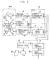
- a control system for controlling the sequence of operation of the combinational weighing apparatus of the structure described above is shown in a block representation in Fig. 2.
- a gate drive unit 27 for selectively opening and closing the gate 13 for each pool hopper 9 is controlled by a pool hopper control 29 and a gate drive unit 28 for selectively opening and closing the gate 14 for each weighing hopper 10 is controlled by a weighing hopper control 30.
- Each of the supply means S for supplying the articles M to be weighed, the weighing device 12 associated with such each supply means S and the associated gate drive units 27 and 28 constitute a weighing head WH.
- the plural weighing heads WH equal in number to the number of the supply means S are arranged around the dispensing feeder 3 and spaced a distance circumferentially of the dispensing feeder 3.
- a chute drive unit 34 for rocking the pivotally supported chute 18 is controlled by a chute control 35.
- a control device 32 comprising, for example, a central processing unit (CPU) has a feed parameter setting means 33, which is a kind of a supply control means, and a combination calculating means 37 both built therein.
- feed parameters such as, for example, the amplitude of and the duration of vibration of the driving feeders
- a feeder control 31 to control the operation of each of the driving feeder 7 to thereby adjust the supply capability thereof.
- the control device 32 is controlled by a mode control means 39.
- the mode control means 39 controls the control means 32 according to a mode of operation selected by a manual mode selector means 38.
- This manual mode selector means 38 is capable of manually selecting one of a weighing mode, in which an ordinary weighing operation is carried out, and a discharge mode in which the articles M to be weighed remaining in the apparatus are discharged outside the apparatus to make it possible to change the articles M.
- the manual mode selector means 38 outputs a change-over signal c indicative of selection of the weighing mode to the mode control means 39.
- the mode control means 39 outputs a weighing mode signal a to both of the feed parameter setting means 33 and the combination calculating means 37 within the control device 32.
- the feed parameter setting means 33 feeds a predetermined parameter for each driving feeder 7 to the feeder drive control 31 which in turn controls the driving feeder 7 of each of the weighing heads WH so that the amplitude of and the duration of vibration of the respective driving feeder 7 can be varied to attain the predetermined feed capability necessary to permit the to-be-weighed articles M, then supplied from the transport conveyor 1 through the dispensing feeder 3 each being controlled by the control device 32, to be supplied onto the pool hoppers 9.
- the feed capability of each driving feeder 7 is so chosen that the total weight of the to-be-weighed articles M within the associated pool hopper 9 can attain a target supply value which varies from one weighing head WH to another weighing head WH with reference to the quotient of a target weight divided by the number of combinations that can be selected.
- This can be achieved through a feedback of the weight (the measured weight) of the articles M within the associated weighing hopper 10 to adjust the feed capability required for the weight to attain the target supply value.
- the feed capability is automatically controlled according to the measured weight of the associated weighing hopper 10 so that the weight of the articles M supplied into such associated weighing hopper 10 can match with the target supply value.
- the combination calculating means 37 is operable in response to a weight signal d fed from the weighing means 11 of each of the weighing devices 12 to perform calculation of a combination of measured weights thereof so as to select a combination of the weighing hoppers 10 which may eventually give the total of the weights of the articles M in the respective weighing hoppers 10 that falls within a permissible range determined according to the target value.
- the combination calculating means 37 outputs a select signal e to the weighing hopper controls 30 associated with some of the weighing hoppers 10 so selected to open the corresponding gates 14 to allow the articles M to be discharged from the selected weighing hoppers 10.
- the pool hopper control 29 of each of the pool hoppers 9 associated with some of the weighing hoppers 10 selected is activated to open the gates 13 of the pool hoppers 9 of the weighing heads WH which have discharged the articles M to allow the subsequent articles M within the pool hoppers 9 to be supplied into the empty weighing hoppers 10.
- the feeder drive control 31 of each of the driving feeders 7 associated with the opened pool hoppers 9 is activated so that the driving feeders 7 of such weighing heads WH are driven to allow the articles M to be supplied into the empty pool hoppers 9 according to the feed parameter set by the feed parameter setting means 33.
- the mode control means 39 which has received the change-over signal c indicative of selection of the discharge mode from the mode selector means 38 outputs a discharge mode signal b to the feed parameter setting means 33, the combination calculating means 37, the pool hopper control 29, the weighing hopper control 30 and the chute control 35. Accordingly, the combination calculating means 37 is brought in an inactive state, and the pool hopper control 29 and the weighing hopper control 30 are held in position to keep the gates 13 and 14 of all of the weighing heads WH in a full open condition.
- the feed parameter setting means 33 having received the discharge mode signal b operates, while the gates 13 and 14 are fully opened, to fix a predetermined feed value at which a maximum feed capability can be attained without being accompanied by clogging and to control all of the driving feeders 7 through the respective feeder drive controls 31.
- the articles M remaining in the transport conveyor 1 and the dispensing feeder 3, both shown in Fig. 1 successively flow through the opened pool hoppers 9 and then through the opened weighing hoppers 10 finally quickly into the collecting chute unit 17.
- the chute control 35 which also has received the discharge mode signal b controls the chute drive unit 34 to cause the pivotally supported chute 18 to pivot from a position, in which the pivotally supported chute 18 are oriented towards the packaging machine 19, to a recovery position A shown by the phantom line in Fig. 1, and accordingly the articles M discharged through the pivotally supported chute 18 then in the recovery position A are recovered for reuse.
- the gates 13 and 14 are held in the full open position and, therefore, no sound of the gates being slammed occur, resulting in considerable reduction in noise level.
- the feed capability of the dispensing feeder 3 is increased by causing the control device 32 to increase the amplitude or the duration of vibration of the oscillator 4 for the dispensing feeder 3 to a value higher than that during the weighing mode.
- the mode selector 38 has to be returned to the weighing mode to initiate the next cycle of combination weighing of the articles M to be weighed.
- the length of time required to initiate the subsequent cycle of combination weighing of the articles M can be advantageously reduced considerably as compared with that exhibited by the prior art combinational weighing apparatus, resulting in increase in efficiency.
- the packaging machine 19 is of a vertical pillow-type, it may occur that without the pivotally supported chute 18 being employed, the remaining articles M may be directly discharged to the packaging machine 19 during the discharge mode. In such case, the bottom of a bag being manufactured may be broken to allow a tubular film being manufactured to serve as a chute through which the remaining articles M can be recovered.
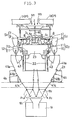
- Fig. 3 illustrates in a schematic front elevational representation the combinational weighing apparatus according to a second preferred embodiment of the present invention.
- This combinational weighing apparatus shown therein is so designed that all of the weighing heads are divided into a plurality of groups so that in each of the groups calculation is carried out to determine a respective combinations within the permissible range to allow the articles to be weighed, which have been determined, to be discharged independently for each group or to be discharged after having been mixed together.
- the second preferred embodiment of the present invention reference is made to mixing of two types of articles M 1 and M 2 to be weighed.
- a vertical partition plate 40 is disposed above the dispensing feeders 3 1 and 3 2 each forming a half of generally flattened conical plate so that two groups of articles M 1 and M 2 can be supplied onto the associated dispensing feeder 3 1 or 3 2 .
- the respective groups of the articles M 1 and M 2 are transported by separate transport conveyors 1 1 and 1 2 and are supplied onto the associated feeder 3 1 or 3 2 , delimited by the partition plate 40, through dividing chutes 2 1 and 2 2 which form respective parts of the guide chute 2.
- Each of the dispensing feeders 3 1 and 3 2 is adapted to be oscillated by a respective oscillator 4 1 or 4 2 drivingly coupled therewith.
- Each transport conveyor 1 1 or 1 2 and the associated dividing chute 2 1 or 2 2 form respective parts of an article delivery means P for delivering the corresponding kinds of the articles M 1 or M 2 .
- the to-be-weighed articles M 1 and M 2 weighed by the respective groups of the weighing hoppers 10 are delivered into associated booster hoppers 43 with the weighing hoppers 10 consequently emptied subsequently loaded again with the to-be-weighed articles M 1 and M 2 .
- the to-be-weighed articles M 1 and M 2 discharged respectively from the hoppers which have been selected by calculation of a combination of the hoppers 10 and the booster hoppers 43 are, after having been collected by collecting chutes 41 1 and 41 2 , respectively, supplied to the packaging machine 19 through the associated pivotally supported chutes 18 1 and 18 2 .
- Each of the collecting chutes 41 1 and 41 2 is of a structure including an upper chute portion 41a, intermediate chute portion 41b positioned below the upper chute portion 41a in communication therewith and a lower chute portion 41c positioned below the intermediate chute portion 41b in communication therewith, all of which are assembled so as to represent the inverted shape of a generally frusto-conical shape.
- Each upper chute portion 41a accommodates therein a respective booster chute 43 for temporarily storing the to-be-weighed articles M 1 or M 2 which have been discharged from the associated weighing hopper 10.
- Each of the pivotally supported chute 18 1 or 18 2 is pivotable between the position, in which the pivotally supported chute 18 1 or 18 2 is oriented towards the packaging machine 19 and the recovery position in which the pivotally supported chute 18 1 or 18 2 is oriented towards a recovery site A 1 and A 2 as shown by the phantom line in Fig. 3.
- each pivotally supported chute 18 1 or 18 2 assumes, independently to the other one, the position facing the packaging machine 19 during the weighing mode, but the recovery position A 1 and A 2 during the discharge mode.
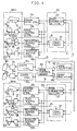
- a control system for controlling the sequence of operation of the combinational weighing apparatus according to the second preferred embodiment described above is shown in a block representation in Fig. 4.
- the plural weighing heads WH are divided by the group dividing means (the partition plate) 40 into two groups each including the driving feeders 7, the pool hoppers 9, the weighing hoppers 10 and the booster hoppers 43.
- the pool hopper controls 29 1 or 29 2 For each of the groups of the weighing heads WH 1 and WH 2 , the pool hopper controls 29 1 or 29 2 , the weighing hopper controls 30 1 or 30 2 , booster hopper controls 46 1 or 46 2 , and the feeder drive controls 31 1 or 31 2 are employed.
- the control device 32 1 or 32 2 , the chute drive unit 34 1 or 34 2 , and the chute control 35 1 or 35 2 are employed.
- the mode control means 39 is connected not only with the mode selector means 38, but also with a group specifying means 48.
- the group specifying means 48 is operable to output a group specifying signal g when one of the groups to be set under the discharge mode is selected by an external manipulation so that the discharge mode signal b from the mode control means 39 can be directed to one of the control devices 32 1 and 32 2 which is associated with the specified group.
- the combinational weighing apparatus shown in and described with reference to Fig. 4 operates in the following manner.
- the weighing mode signal a is outputted from the mode control means 39 to each of the control devices 32 1 and 32 2 to allow each of the control devices 32 1 and 32 2 to control the associated weighing heads WH 1 , or WH 2 in a manner similar to that described with reference to Fig. 2.
- the feed parameter setting means 33 and 33 of the respective control devices 32 1 and 32 2 apply individually predetermined feed parameters to the associated feeder driving means 31 1 and 31 2 to thereby control the driving feeders 7 and 7.
- each of the combination calculating means 37 and 37 operate in response to receipt of a corresponding weighing signal d1 or d2 fed from one of the weighing devices 12 and 12, which belongs to the associated group, to perform a combinational calculation with respect to the weight of the to-be-weighed articles and the weight (represented by the weight signal generated from the weighing devices 12 1 or 12 2 during the previous cycle of weighing) of the to-be-weighed articles transferred onto the booster hoppers 43 to thereby select a combination of the weighing hoppers 10 and the booster hoppers 43 falling within a permissible range for each group so that the gates 14 of the selected weighing hoppers 10 can be opened by the gate drive units 28 1 or 28 2 through the weighing hopper control 30 1 or 30 2 and, at the same time, gates 44 of the selected booster hoppers 43 can be opened by gate drive units 45 through the booster hopper control 46 1 or 46 2 .
- the articles M 1 and M 2 discharged from the weighing hoppers 10 of the respective groups and the associated booster hoppers 43 are, after having been mixed together through the collecting chutes 41 1 and 41 2 and then through the pivotally supported chutes 18 1 and 18 2 , supplied to the packaging machine 19.
- the pivotally supported chutes 18 1 and 18 2 may be operatively coupled with separate packaging machines so that the articles M 1 and M 2 can be supplied to separate packaging machines, respectively.
- the mode selector means 38 has to be manipulated to select the discharge mode and the group specifying means 48 is also operated to specify one of the groups.
- the mode control means 39 supplies the discharge mode signal b to one of the control devices of the specified group, for example, the control device 31 1 , causing the control device 32 1 to retain the pool hoppers 9, the weighing hoppers 10 and the booster hoppers 43 of the corresponding weighing heads WH 1 in a full open position in a manner similar to that described in connection with the control system shown in Fig. 2.
- the to-be-weighed articles M 1 remaining on the transport conveyor 1 1 and the dispensing feeder 3 successively flow and are quickly discharged through the pool hoppers 9 and the weighing hoppers 10 and, at the same time, the to-be-weighed articles remaining within the booster hoppers 43 are also discharged.
- the feed capability of the dispensing feeder 3 1 is preferred to be of a value higher than that exhibited during the weighing mode.
- the other of the groups is specified by the group specifying means 48, the to-be-weighed articles M 2 are similarly allowed to flow and be quickly discharged through the pool hoppers 9 and the weighing hoppers 10 of the weighing heads WH 2 then retained in the opened position and, at the same time, the articles remaining within the booster hoppers 43 are also discharged.
- the pivotally supported chute 18 1 or 18 2 of the specified group which has received the discharge mode signal b are pivoted from the position facing the packaging machine 19 to the discharge position facing the recovery site A 1 and A 2 shown in Fig. 3 by the chute drive unit 34 then activated by the chute controls 35 1 and 35 2 which have received the discharge mode signal b. Accordingly, the two kinds of the articles M 1 and M 2 are recovered for reuse without being mixed together.
- the system is not the one in which the two groups are continuously switched over to the discharge mode as hereinabove described, but the two groups may be switched over to the discharge mode simultaneously. Or either one of the groups can be switched over to the discharge mode. Where the two groups are switched over to the discharge mode at different timings delayed relative to each other, not simultaneously, it is sufficient to use a single pivotally supported chute 18 for both of the groups.
- one of the groups is specified by the group specifying means 48.
- the discharge mode signal b is supplied only to the control device 32 1 associated with the specified group so that the control device 32 1 can control the weighing heads WH 1 in the manner described above to facilitate a quick discharge of the articles M 1 .
- the control device 32 2 associated with the non-specified group receives neither the weighing signal a nor the discharge mode signal b and, therefore, such control device 32 2 is held in an inactive state.
- the present invention can be equally applied to the case in which the single apparatus is divided into three or more groups so that three or more kinds of articles can be handled.
- the number of pieces within the permissible range may be determined and conversion of the measured weight into the number of pieces may be made so that a combination can be selected to allow the converted number of pieces to fall within the permissible range.
- supply means S or S 1 and S 2 for supplying the to-be-weighed articles to the weighing hoppers 10 have been described as constituted by the driving feeders 7 and the pool hoppers 9, the supply means may not be always limited thereto, but may be of a type having, for example, no pool hopper.
Landscapes
- Physics & Mathematics (AREA)
- General Physics & Mathematics (AREA)
- Engineering & Computer Science (AREA)
- Mathematical Physics (AREA)
- Theoretical Computer Science (AREA)
- Weight Measurement For Supplying Or Discharging Of Specified Amounts Of Material (AREA)
- Supply Of Fluid Materials To The Packaging Location (AREA)
Applications Claiming Priority (3)
| Application Number | Priority Date | Filing Date | Title |
|---|---|---|---|
| JP39350/95 | 1995-02-02 | ||
| JP3935095 | 1995-02-02 | ||
| JP3935095 | 1995-02-02 |
Publications (2)
| Publication Number | Publication Date |
|---|---|
| EP0725263A1 true EP0725263A1 (fr) | 1996-08-07 |
| EP0725263B1 EP0725263B1 (fr) | 2000-03-15 |
Family
ID=12550638
Family Applications (1)
| Application Number | Title | Priority Date | Filing Date |
|---|---|---|---|
| EP96101341A Expired - Lifetime EP0725263B1 (fr) | 1995-02-02 | 1996-01-31 | Dispositif pour la pesée combinatoire |
Country Status (3)
| Country | Link |
|---|---|
| US (1) | US5753867A (fr) |
| EP (1) | EP0725263B1 (fr) |
| DE (1) | DE69607051T2 (fr) |
Cited By (7)
| Publication number | Priority date | Publication date | Assignee | Title |
|---|---|---|---|---|
| WO1999045347A1 (fr) * | 1998-03-02 | 1999-09-10 | MULTIPOND Wägetechnik GmbH | Dispositif de distribution d'un produit d'un systeme de preparation de produit |
| EP0945716A1 (fr) * | 1998-03-18 | 1999-09-29 | Multipond Wägetechnik Gmbh | Dispositif de pesage combinatoire |
| EP1048937A1 (fr) * | 1999-04-26 | 2000-11-02 | Ishida Co., Ltd. | Dispositif de pesage combinatoire avec décharge échelonnée |
| EP1319932A2 (fr) | 2001-12-13 | 2003-06-18 | Ishida Co., Ltd. | Dispositif de pesage combinatoire |
| CN102424122A (zh) * | 2011-08-12 | 2012-04-25 | 广东海川智能机器有限公司 | 组合秤及其控制方法 |
| EP2463630A1 (fr) * | 2010-12-13 | 2012-06-13 | Ishida Co., Ltd. | Dispositif de pesage combinatoire |
| EP2700914A1 (fr) * | 2012-08-23 | 2014-02-26 | Ishida Europe Limited | Appareil de pesage à plusieurs têtes |
Families Citing this family (26)
| Publication number | Priority date | Publication date | Assignee | Title |
|---|---|---|---|---|
| JP4169836B2 (ja) * | 1998-08-04 | 2008-10-22 | 株式会社イシダ | 計量包装システム |
| ATE245806T1 (de) * | 1999-05-03 | 2003-08-15 | Bilwinco As | Wägeapparat |
| WO2001048448A1 (fr) * | 1999-12-24 | 2001-07-05 | Ishida Co., Ltd. | Dispositif de comptage et de pesage par lots |
| JP3537772B2 (ja) * | 2001-01-19 | 2004-06-14 | 株式会社イシダ | 組合せ計量装置 |
| JP4669627B2 (ja) * | 2001-04-26 | 2011-04-13 | 株式会社イシダ | 組合せ計量装置及び組合せ計量包装システム |
| JP3785090B2 (ja) * | 2001-12-13 | 2006-06-14 | 株式会社イシダ | 組合せ計量装置 |
| AUPS070602A0 (en) * | 2002-02-22 | 2002-03-21 | Tna Australia Pty Limited | Timing gates for a packaging machine |
| US20070000939A1 (en) * | 2002-10-29 | 2007-01-04 | Vasilios Vasiadis | Device for handling and orientating pills or tablets in a precise manner |
| US20050092660A1 (en) * | 2003-10-29 | 2005-05-05 | Vasilios Vasiadis | Device for handling and orientating pills or tablets in a precise manner |
| DE102005004751A1 (de) * | 2005-01-28 | 2006-08-03 | Nordischer Maschinenbau Rud. Baader Gmbh + Co Kg | Vorrichtung und Verfahren zum gewichtskontrollierten Zusammenstellen von Produkten zu einem Los |
| JP2006300654A (ja) * | 2005-04-19 | 2006-11-02 | Katsuzo Kawanishi | 混合計量用組合せ秤 |
| US20070194034A1 (en) * | 2006-02-17 | 2007-08-23 | Vasilios Vasiadis | Device for printing pills, tablets or caplets in a precise manner |
| US20080091299A1 (en) * | 2006-10-13 | 2008-04-17 | Ishida Co., Ltd. | Weighing and packaging system and setting input device for product processing system |
| US7952036B2 (en) * | 2008-10-30 | 2011-05-31 | Yamato Corporation | Combinational weigher with a recycle conveyor configured to allow products to be recirculated in a dispersed manner |
| US7790990B2 (en) * | 2008-10-30 | 2010-09-07 | Yamato Corporation | Combination weigher with peripheral annular recycling table |
| US8735746B2 (en) * | 2010-01-11 | 2014-05-27 | Campbell Wrapper Corporation | Weighing apparatus and method |
| DE102013010048A1 (de) * | 2013-06-17 | 2014-12-18 | Haver & Boecker Ohg | Packmaschine und Verfahren |
| GB201407651D0 (en) * | 2014-05-01 | 2014-06-18 | Ishida Europ Ltd | Method and apparatus for grading food pieces |
| JP6557557B2 (ja) * | 2015-09-02 | 2019-08-07 | 株式会社イシダ | 組合せ計量装置 |
| CN108474688B (zh) * | 2016-01-07 | 2020-07-03 | 株式会社石田 | 组合计量装置 |
| DE102017130958A1 (de) * | 2017-12-21 | 2019-06-27 | Haver & Boecker Ohg | Packmaschine und Verfahren zum Füllen von Schüttgütern in Gebinde |
| JP7114190B2 (ja) * | 2018-12-19 | 2022-08-08 | 大和製衡株式会社 | 組合せ計量装置 |
| JP7114189B2 (ja) * | 2018-12-19 | 2022-08-08 | 大和製衡株式会社 | 組合せ計量装置 |
| JP7672683B2 (ja) * | 2021-03-12 | 2025-05-08 | 株式会社イシダ | 物品搬送装置、及び組合せ計量装置 |
| JP7701040B2 (ja) * | 2021-10-05 | 2025-07-01 | 株式会社イシダ | 組合せ計量装置 |
| JP2024115913A (ja) * | 2023-02-15 | 2024-08-27 | 株式会社イシダ | 供給装置 |
Citations (3)
| Publication number | Priority date | Publication date | Assignee | Title |
|---|---|---|---|---|
| GB2074329A (en) * | 1980-03-25 | 1981-10-28 | Ishida Scale Mfg Co Ltd | Automatic weighing apparatus |
| EP0267664A2 (fr) * | 1986-11-14 | 1988-05-18 | Ishida Scales Mfg. Co. Ltd. | Système de réglage par ordinateur |
| EP0298736A2 (fr) * | 1987-07-08 | 1989-01-11 | Yamato Scale Company, Limited | Dispositif pour mettre au point les conditions opérationnelles pour une machine de pesage combinatoire |
Family Cites Families (3)
| Publication number | Priority date | Publication date | Assignee | Title |
|---|---|---|---|---|
| AU554610B2 (en) * | 1984-04-25 | 1986-08-28 | Ishida Scales Mfg. Co. Ltd. | Combinatorial weighing method |
| JPH0672797B2 (ja) * | 1984-04-25 | 1994-09-14 | 株式会社石田衡器製作所 | 組合せ計量装置と包装機との連動システム |
| JPH0663814B2 (ja) * | 1984-04-26 | 1994-08-22 | 株式会社石田衡器製作所 | 自動秤量機 |
-
1996
- 1996-01-30 US US08/593,840 patent/US5753867A/en not_active Expired - Lifetime
- 1996-01-31 EP EP96101341A patent/EP0725263B1/fr not_active Expired - Lifetime
- 1996-01-31 DE DE69607051T patent/DE69607051T2/de not_active Expired - Lifetime
Patent Citations (3)
| Publication number | Priority date | Publication date | Assignee | Title |
|---|---|---|---|---|
| GB2074329A (en) * | 1980-03-25 | 1981-10-28 | Ishida Scale Mfg Co Ltd | Automatic weighing apparatus |
| EP0267664A2 (fr) * | 1986-11-14 | 1988-05-18 | Ishida Scales Mfg. Co. Ltd. | Système de réglage par ordinateur |
| EP0298736A2 (fr) * | 1987-07-08 | 1989-01-11 | Yamato Scale Company, Limited | Dispositif pour mettre au point les conditions opérationnelles pour une machine de pesage combinatoire |
Cited By (10)
| Publication number | Priority date | Publication date | Assignee | Title |
|---|---|---|---|---|
| WO1999045347A1 (fr) * | 1998-03-02 | 1999-09-10 | MULTIPOND Wägetechnik GmbH | Dispositif de distribution d'un produit d'un systeme de preparation de produit |
| EP0945716A1 (fr) * | 1998-03-18 | 1999-09-29 | Multipond Wägetechnik Gmbh | Dispositif de pesage combinatoire |
| EP1048937A1 (fr) * | 1999-04-26 | 2000-11-02 | Ishida Co., Ltd. | Dispositif de pesage combinatoire avec décharge échelonnée |
| US6365846B1 (en) | 1999-04-26 | 2002-04-02 | Ishida Co., Ltd. | Combination weighing apparatus with improved flow of articles |
| EP1319932A2 (fr) | 2001-12-13 | 2003-06-18 | Ishida Co., Ltd. | Dispositif de pesage combinatoire |
| EP1319932A3 (fr) * | 2001-12-13 | 2006-12-20 | Ishida Co., Ltd. | Dispositif de pesage combinatoire |
| EP2463630A1 (fr) * | 2010-12-13 | 2012-06-13 | Ishida Co., Ltd. | Dispositif de pesage combinatoire |
| CN102424122A (zh) * | 2011-08-12 | 2012-04-25 | 广东海川智能机器有限公司 | 组合秤及其控制方法 |
| CN102424122B (zh) * | 2011-08-12 | 2013-08-21 | 广东海川智能机器有限公司 | 组合秤的控制方法 |
| EP2700914A1 (fr) * | 2012-08-23 | 2014-02-26 | Ishida Europe Limited | Appareil de pesage à plusieurs têtes |
Also Published As
| Publication number | Publication date |
|---|---|
| US5753867A (en) | 1998-05-19 |
| DE69607051D1 (de) | 2000-04-20 |
| EP0725263B1 (fr) | 2000-03-15 |
| DE69607051T2 (de) | 2000-12-21 |
Similar Documents
| Publication | Publication Date | Title |
|---|---|---|
| EP0725263B1 (fr) | Dispositif pour la pesée combinatoire | |
| US4844190A (en) | Combinational weigher for multiple operations | |
| EP0097532B1 (fr) | Dispositif de pesage combinatoire | |
| GB2203847A (en) | Combinational weighing systems | |
| EP1209452A1 (fr) | Dispositif de pesage | |
| EP0576223B1 (fr) | Machine de pesage en combination avec un contrÔle special d'alimentation | |
| EP0866004B1 (fr) | Dispositif d'alignement d'articles | |
| US4813503A (en) | Method and apparatus for preparing a blended product charge | |
| US4511010A (en) | Combinatorial weighing method and apparatus therefor | |
| JPH08271328A (ja) | 組合せ計量・計数システム | |
| GB2131962A (en) | Metering fluent material | |
| EP0105756B1 (fr) | Dispositif de pesage combinatoire et méthode | |
| JP2025517486A (ja) | 分配供給器の不良を特定する方法 | |
| JP4518523B2 (ja) | 組合せ計量装置 | |
| JP2002116082A (ja) | 組合せ計量装置 | |
| JP2673065B2 (ja) | 組合せ計量機 | |
| JPH0254886B2 (fr) | ||
| JP2000205935A (ja) | 組合せ計量・計数方法およびその装置 | |
| JP4519215B2 (ja) | 組合せ計量計数装置 | |
| JP4686007B2 (ja) | 組合せ計量装置 | |
| CN221367686U (zh) | 一种输送带分料式组合秤 | |
| EP4446709B1 (fr) | Dispositif de pesée par combinaison | |
| JPH02132011A (ja) | 粉粒体排出装置 | |
| JPH0639352A (ja) | 多段階重量選別機 | |
| JP4833658B2 (ja) | 組合せ計量装置 |
Legal Events
| Date | Code | Title | Description |
|---|---|---|---|
| PUAI | Public reference made under article 153(3) epc to a published international application that has entered the european phase |
Free format text: ORIGINAL CODE: 0009012 |
|
| AK | Designated contracting states |
Kind code of ref document: A1 Designated state(s): DE FR GB IT |
|
| 17P | Request for examination filed |
Effective date: 19960806 |
|
| 17Q | First examination report despatched |
Effective date: 19980928 |
|
| GRAG | Despatch of communication of intention to grant |
Free format text: ORIGINAL CODE: EPIDOS AGRA |
|
| GRAG | Despatch of communication of intention to grant |
Free format text: ORIGINAL CODE: EPIDOS AGRA |
|
| GRAH | Despatch of communication of intention to grant a patent |
Free format text: ORIGINAL CODE: EPIDOS IGRA |
|
| GRAH | Despatch of communication of intention to grant a patent |
Free format text: ORIGINAL CODE: EPIDOS IGRA |
|
| GRAA | (expected) grant |
Free format text: ORIGINAL CODE: 0009210 |
|
| AK | Designated contracting states |
Kind code of ref document: B1 Designated state(s): DE FR GB IT |
|
| ET | Fr: translation filed | ||
| REF | Corresponds to: |
Ref document number: 69607051 Country of ref document: DE Date of ref document: 20000420 |
|
| ITF | It: translation for a ep patent filed | ||
| PLBE | No opposition filed within time limit |
Free format text: ORIGINAL CODE: 0009261 |
|
| STAA | Information on the status of an ep patent application or granted ep patent |
Free format text: STATUS: NO OPPOSITION FILED WITHIN TIME LIMIT |
|
| 26N | No opposition filed | ||
| REG | Reference to a national code |
Ref country code: GB Ref legal event code: IF02 |
|
| PGFP | Annual fee paid to national office [announced via postgrant information from national office to epo] |
Ref country code: FR Payment date: 20110202 Year of fee payment: 16 Ref country code: IT Payment date: 20110125 Year of fee payment: 16 |
|
| REG | Reference to a national code |
Ref country code: FR Ref legal event code: ST Effective date: 20120928 |
|
| PG25 | Lapsed in a contracting state [announced via postgrant information from national office to epo] |
Ref country code: IT Free format text: LAPSE BECAUSE OF NON-PAYMENT OF DUE FEES Effective date: 20120131 |
|
| PG25 | Lapsed in a contracting state [announced via postgrant information from national office to epo] |
Ref country code: FR Free format text: LAPSE BECAUSE OF NON-PAYMENT OF DUE FEES Effective date: 20120131 |
|
| PGFP | Annual fee paid to national office [announced via postgrant information from national office to epo] |
Ref country code: DE Payment date: 20140122 Year of fee payment: 19 |
|
| PGFP | Annual fee paid to national office [announced via postgrant information from national office to epo] |
Ref country code: GB Payment date: 20140121 Year of fee payment: 19 |
|
| REG | Reference to a national code |
Ref country code: DE Ref legal event code: R119 Ref document number: 69607051 Country of ref document: DE |
|
| GBPC | Gb: european patent ceased through non-payment of renewal fee |
Effective date: 20150131 |
|
| PG25 | Lapsed in a contracting state [announced via postgrant information from national office to epo] |
Ref country code: GB Free format text: LAPSE BECAUSE OF NON-PAYMENT OF DUE FEES Effective date: 20150131 Ref country code: DE Free format text: LAPSE BECAUSE OF NON-PAYMENT OF DUE FEES Effective date: 20150801 |