EP0725842B1 - Abreibbare plasma gespritzte dichtungen für gasturbinen - Google Patents
Abreibbare plasma gespritzte dichtungen für gasturbinen Download PDFInfo
- Publication number
- EP0725842B1 EP0725842B1 EP95903101A EP95903101A EP0725842B1 EP 0725842 B1 EP0725842 B1 EP 0725842B1 EP 95903101 A EP95903101 A EP 95903101A EP 95903101 A EP95903101 A EP 95903101A EP 0725842 B1 EP0725842 B1 EP 0725842B1
- Authority
- EP
- European Patent Office
- Prior art keywords
- percent
- less
- set forth
- abradable
- seal
- Prior art date
- Legal status (The legal status is an assumption and is not a legal conclusion. Google has not performed a legal analysis and makes no representation as to the accuracy of the status listed.)
- Expired - Lifetime
Links
- 229910052582 BN Inorganic materials 0.000 claims description 44
- PZNSFCLAULLKQX-UHFFFAOYSA-N Boron nitride Chemical compound N#B PZNSFCLAULLKQX-UHFFFAOYSA-N 0.000 claims description 43
- 239000007789 gas Substances 0.000 claims description 35
- PXHVJJICTQNCMI-UHFFFAOYSA-N Nickel Chemical compound [Ni] PXHVJJICTQNCMI-UHFFFAOYSA-N 0.000 claims description 34
- 230000003647 oxidation Effects 0.000 claims description 33
- 238000007254 oxidation reaction Methods 0.000 claims description 33
- 238000000034 method Methods 0.000 claims description 30
- 239000007921 spray Substances 0.000 claims description 23
- 229910000601 superalloy Inorganic materials 0.000 claims description 23
- 230000003628 erosive effect Effects 0.000 claims description 19
- 239000002245 particle Substances 0.000 claims description 18
- 239000000843 powder Substances 0.000 claims description 18
- 239000002131 composite material Substances 0.000 claims description 17
- 229910052759 nickel Inorganic materials 0.000 claims description 15
- 239000010936 titanium Substances 0.000 claims description 14
- XEEYBQQBJWHFJM-UHFFFAOYSA-N Iron Chemical compound [Fe] XEEYBQQBJWHFJM-UHFFFAOYSA-N 0.000 claims description 13
- 239000000758 substrate Substances 0.000 claims description 13
- 230000003746 surface roughness Effects 0.000 claims description 13
- 230000035699 permeability Effects 0.000 claims description 12
- 229910052735 hafnium Inorganic materials 0.000 claims description 11
- VBJZVLUMGGDVMO-UHFFFAOYSA-N hafnium atom Chemical compound [Hf] VBJZVLUMGGDVMO-UHFFFAOYSA-N 0.000 claims description 11
- 238000007750 plasma spraying Methods 0.000 claims description 11
- 229910052727 yttrium Inorganic materials 0.000 claims description 11
- VWQVUPCCIRVNHF-UHFFFAOYSA-N yttrium atom Chemical compound [Y] VWQVUPCCIRVNHF-UHFFFAOYSA-N 0.000 claims description 11
- 238000002347 injection Methods 0.000 claims description 10
- 239000007924 injection Substances 0.000 claims description 10
- 229910045601 alloy Inorganic materials 0.000 claims description 9
- 239000000956 alloy Substances 0.000 claims description 9
- 239000000470 constituent Substances 0.000 claims description 9
- 229910001120 nichrome Inorganic materials 0.000 claims description 8
- 239000010949 copper Substances 0.000 claims description 7
- 229910052742 iron Inorganic materials 0.000 claims description 6
- 238000005259 measurement Methods 0.000 claims description 6
- NINIDFKCEFEMDL-UHFFFAOYSA-N Sulfur Chemical compound [S] NINIDFKCEFEMDL-UHFFFAOYSA-N 0.000 claims description 5
- 229910052797 bismuth Inorganic materials 0.000 claims description 5
- JCXGWMGPZLAOME-UHFFFAOYSA-N bismuth atom Chemical compound [Bi] JCXGWMGPZLAOME-UHFFFAOYSA-N 0.000 claims description 5
- 229910052802 copper Inorganic materials 0.000 claims description 5
- 229910052717 sulfur Inorganic materials 0.000 claims description 5
- 239000011593 sulfur Substances 0.000 claims description 5
- RYGMFSIKBFXOCR-UHFFFAOYSA-N Copper Chemical compound [Cu] RYGMFSIKBFXOCR-UHFFFAOYSA-N 0.000 claims description 4
- BHEPBYXIRTUNPN-UHFFFAOYSA-N hydridophosphorus(.) (triplet) Chemical compound [PH] BHEPBYXIRTUNPN-UHFFFAOYSA-N 0.000 claims description 4
- 239000011572 manganese Substances 0.000 claims description 4
- 238000002360 preparation method Methods 0.000 claims description 4
- 238000005507 spraying Methods 0.000 claims description 4
- 239000011573 trace mineral Substances 0.000 claims description 4
- 235000013619 trace mineral Nutrition 0.000 claims description 4
- WPBNNNQJVZRUHP-UHFFFAOYSA-L manganese(2+);methyl n-[[2-(methoxycarbonylcarbamothioylamino)phenyl]carbamothioyl]carbamate;n-[2-(sulfidocarbothioylamino)ethyl]carbamodithioate Chemical compound [Mn+2].[S-]C(=S)NCCNC([S-])=S.COC(=O)NC(=S)NC1=CC=CC=C1NC(=S)NC(=O)OC WPBNNNQJVZRUHP-UHFFFAOYSA-L 0.000 claims description 3
- 239000012159 carrier gas Substances 0.000 claims description 2
- 230000001747 exhibiting effect Effects 0.000 claims description 2
- 230000001464 adherent effect Effects 0.000 claims 2
- 238000000576 coating method Methods 0.000 description 42
- 239000011248 coating agent Substances 0.000 description 31
- 239000000463 material Substances 0.000 description 28
- 229910052751 metal Inorganic materials 0.000 description 28
- 239000002184 metal Substances 0.000 description 28
- 239000010410 layer Substances 0.000 description 17
- 239000011159 matrix material Substances 0.000 description 14
- 230000008569 process Effects 0.000 description 10
- RTAQQCXQSZGOHL-UHFFFAOYSA-N Titanium Chemical compound [Ti] RTAQQCXQSZGOHL-UHFFFAOYSA-N 0.000 description 8
- 239000000203 mixture Substances 0.000 description 8
- 229910052719 titanium Inorganic materials 0.000 description 8
- 230000008901 benefit Effects 0.000 description 7
- 238000012360 testing method Methods 0.000 description 7
- 239000011651 chromium Substances 0.000 description 6
- OKTJSMMVPCPJKN-UHFFFAOYSA-N Carbon Chemical compound [C] OKTJSMMVPCPJKN-UHFFFAOYSA-N 0.000 description 5
- VYZAMTAEIAYCRO-UHFFFAOYSA-N Chromium Chemical compound [Cr] VYZAMTAEIAYCRO-UHFFFAOYSA-N 0.000 description 5
- 229910052782 aluminium Inorganic materials 0.000 description 5
- XAGFODPZIPBFFR-UHFFFAOYSA-N aluminium Chemical compound [Al] XAGFODPZIPBFFR-UHFFFAOYSA-N 0.000 description 5
- 229910052799 carbon Inorganic materials 0.000 description 5
- 229910052804 chromium Inorganic materials 0.000 description 5
- 238000009826 distribution Methods 0.000 description 5
- 230000006872 improvement Effects 0.000 description 5
- 230000003993 interaction Effects 0.000 description 5
- 239000000314 lubricant Substances 0.000 description 5
- VYPSYNLAJGMNEJ-UHFFFAOYSA-N Silicium dioxide Chemical compound O=[Si]=O VYPSYNLAJGMNEJ-UHFFFAOYSA-N 0.000 description 4
- 230000007423 decrease Effects 0.000 description 4
- 230000000694 effects Effects 0.000 description 4
- 238000011065 in-situ storage Methods 0.000 description 4
- 239000010955 niobium Substances 0.000 description 4
- 230000002829 reductive effect Effects 0.000 description 4
- XUIMIQQOPSSXEZ-UHFFFAOYSA-N Silicon Chemical compound [Si] XUIMIQQOPSSXEZ-UHFFFAOYSA-N 0.000 description 3
- 229910052796 boron Inorganic materials 0.000 description 3
- 239000010941 cobalt Substances 0.000 description 3
- 229910017052 cobalt Inorganic materials 0.000 description 3
- 238000002485 combustion reaction Methods 0.000 description 3
- 230000008030 elimination Effects 0.000 description 3
- 238000003379 elimination reaction Methods 0.000 description 3
- 238000005516 engineering process Methods 0.000 description 3
- 238000010438 heat treatment Methods 0.000 description 3
- 230000001050 lubricating effect Effects 0.000 description 3
- 229910052750 molybdenum Inorganic materials 0.000 description 3
- 239000011733 molybdenum Substances 0.000 description 3
- 230000005855 radiation Effects 0.000 description 3
- 238000007712 rapid solidification Methods 0.000 description 3
- 239000011819 refractory material Substances 0.000 description 3
- 229910052710 silicon Inorganic materials 0.000 description 3
- 239000010703 silicon Substances 0.000 description 3
- 230000035882 stress Effects 0.000 description 3
- 229910052715 tantalum Inorganic materials 0.000 description 3
- WFKWXMTUELFFGS-UHFFFAOYSA-N tungsten Chemical compound [W] WFKWXMTUELFFGS-UHFFFAOYSA-N 0.000 description 3
- 229910052721 tungsten Inorganic materials 0.000 description 3
- 239000010937 tungsten Substances 0.000 description 3
- IJGRMHOSHXDMSA-UHFFFAOYSA-N Atomic nitrogen Chemical compound N#N IJGRMHOSHXDMSA-UHFFFAOYSA-N 0.000 description 2
- ZOXJGFHDIHLPTG-UHFFFAOYSA-N Boron Chemical compound [B] ZOXJGFHDIHLPTG-UHFFFAOYSA-N 0.000 description 2
- PWHULOQIROXLJO-UHFFFAOYSA-N Manganese Chemical compound [Mn] PWHULOQIROXLJO-UHFFFAOYSA-N 0.000 description 2
- ZOKXTWBITQBERF-UHFFFAOYSA-N Molybdenum Chemical compound [Mo] ZOKXTWBITQBERF-UHFFFAOYSA-N 0.000 description 2
- GUTLYIVDDKVIGB-UHFFFAOYSA-N cobalt atom Chemical compound [Co] GUTLYIVDDKVIGB-UHFFFAOYSA-N 0.000 description 2
- 238000005336 cracking Methods 0.000 description 2
- 238000000151 deposition Methods 0.000 description 2
- 230000001066 destructive effect Effects 0.000 description 2
- 239000000945 filler Substances 0.000 description 2
- 238000010285 flame spraying Methods 0.000 description 2
- 229910052748 manganese Inorganic materials 0.000 description 2
- 230000013011 mating Effects 0.000 description 2
- 238000002844 melting Methods 0.000 description 2
- 230000008018 melting Effects 0.000 description 2
- 239000007769 metal material Substances 0.000 description 2
- 238000012545 processing Methods 0.000 description 2
- 239000011347 resin Substances 0.000 description 2
- 229920005989 resin Polymers 0.000 description 2
- 229910052702 rhenium Inorganic materials 0.000 description 2
- WUAPFZMCVAUBPE-UHFFFAOYSA-N rhenium atom Chemical compound [Re] WUAPFZMCVAUBPE-UHFFFAOYSA-N 0.000 description 2
- 239000007787 solid Substances 0.000 description 2
- 230000002459 sustained effect Effects 0.000 description 2
- GUVRBAGPIYLISA-UHFFFAOYSA-N tantalum atom Chemical compound [Ta] GUVRBAGPIYLISA-UHFFFAOYSA-N 0.000 description 2
- 230000008646 thermal stress Effects 0.000 description 2
- 238000012546 transfer Methods 0.000 description 2
- 229910052726 zirconium Inorganic materials 0.000 description 2
- 229910000531 Co alloy Inorganic materials 0.000 description 1
- UFHFLCQGNIYNRP-UHFFFAOYSA-N Hydrogen Chemical compound [H][H] UFHFLCQGNIYNRP-UHFFFAOYSA-N 0.000 description 1
- 239000005909 Kieselgur Substances 0.000 description 1
- 229920005479 Lucite® Polymers 0.000 description 1
- 229910000990 Ni alloy Inorganic materials 0.000 description 1
- 229910001069 Ti alloy Inorganic materials 0.000 description 1
- QCWXUUIWCKQGHC-UHFFFAOYSA-N Zirconium Chemical compound [Zr] QCWXUUIWCKQGHC-UHFFFAOYSA-N 0.000 description 1
- 238000005299 abrasion Methods 0.000 description 1
- 238000013459 approach Methods 0.000 description 1
- 230000004888 barrier function Effects 0.000 description 1
- 230000009286 beneficial effect Effects 0.000 description 1
- 230000015572 biosynthetic process Effects 0.000 description 1
- 238000004140 cleaning Methods 0.000 description 1
- 239000011247 coating layer Substances 0.000 description 1
- 230000000052 comparative effect Effects 0.000 description 1
- 238000001816 cooling Methods 0.000 description 1
- 230000007797 corrosion Effects 0.000 description 1
- 238000005260 corrosion Methods 0.000 description 1
- 230000003247 decreasing effect Effects 0.000 description 1
- 230000008021 deposition Effects 0.000 description 1
- 238000005137 deposition process Methods 0.000 description 1
- 238000011161 development Methods 0.000 description 1
- 239000000428 dust Substances 0.000 description 1
- 238000011049 filling Methods 0.000 description 1
- 230000010006 flight Effects 0.000 description 1
- 239000000446 fuel Substances 0.000 description 1
- 229910002804 graphite Inorganic materials 0.000 description 1
- 239000010439 graphite Substances 0.000 description 1
- 239000001257 hydrogen Substances 0.000 description 1
- 229910052739 hydrogen Inorganic materials 0.000 description 1
- 239000012535 impurity Substances 0.000 description 1
- 238000012625 in-situ measurement Methods 0.000 description 1
- 229910001119 inconels 625 Inorganic materials 0.000 description 1
- 229910000816 inconels 718 Inorganic materials 0.000 description 1
- 239000011261 inert gas Substances 0.000 description 1
- 230000002401 inhibitory effect Effects 0.000 description 1
- 229910052746 lanthanum Inorganic materials 0.000 description 1
- FZLIPJUXYLNCLC-UHFFFAOYSA-N lanthanum atom Chemical compound [La] FZLIPJUXYLNCLC-UHFFFAOYSA-N 0.000 description 1
- 230000000670 limiting effect Effects 0.000 description 1
- 230000007774 longterm Effects 0.000 description 1
- CPLXHLVBOLITMK-UHFFFAOYSA-N magnesium oxide Inorganic materials [Mg]=O CPLXHLVBOLITMK-UHFFFAOYSA-N 0.000 description 1
- 239000000395 magnesium oxide Substances 0.000 description 1
- AXZKOIWUVFPNLO-UHFFFAOYSA-N magnesium;oxygen(2-) Chemical compound [O-2].[Mg+2] AXZKOIWUVFPNLO-UHFFFAOYSA-N 0.000 description 1
- 238000004519 manufacturing process Methods 0.000 description 1
- 239000013528 metallic particle Substances 0.000 description 1
- 150000002739 metals Chemical class 0.000 description 1
- 239000010445 mica Substances 0.000 description 1
- 229910052618 mica group Inorganic materials 0.000 description 1
- 238000002156 mixing Methods 0.000 description 1
- 238000012986 modification Methods 0.000 description 1
- 230000004048 modification Effects 0.000 description 1
- -1 nickel-chromium-aluminum-boron Chemical compound 0.000 description 1
- 229910052758 niobium Inorganic materials 0.000 description 1
- GUCVJGMIXFAOAE-UHFFFAOYSA-N niobium atom Chemical compound [Nb] GUCVJGMIXFAOAE-UHFFFAOYSA-N 0.000 description 1
- 229910052757 nitrogen Inorganic materials 0.000 description 1
- 229910052760 oxygen Inorganic materials 0.000 description 1
- 239000001301 oxygen Substances 0.000 description 1
- 239000013618 particulate matter Substances 0.000 description 1
- 230000035515 penetration Effects 0.000 description 1
- 229920003229 poly(methyl methacrylate) Polymers 0.000 description 1
- 229920000642 polymer Polymers 0.000 description 1
- 239000004926 polymethyl methacrylate Substances 0.000 description 1
- 238000004663 powder metallurgy Methods 0.000 description 1
- 238000010248 power generation Methods 0.000 description 1
- 239000002243 precursor Substances 0.000 description 1
- 238000003825 pressing Methods 0.000 description 1
- 230000009467 reduction Effects 0.000 description 1
- 150000003839 salts Chemical class 0.000 description 1
- 238000005204 segregation Methods 0.000 description 1
- 239000000377 silicon dioxide Substances 0.000 description 1
- 235000012239 silicon dioxide Nutrition 0.000 description 1
- 238000005245 sintering Methods 0.000 description 1
- 125000006850 spacer group Chemical group 0.000 description 1
- 239000002344 surface layer Substances 0.000 description 1
- 238000010301 surface-oxidation reaction Methods 0.000 description 1
- 238000007751 thermal spraying Methods 0.000 description 1
- 229910001247 waspaloy Inorganic materials 0.000 description 1
- XLYOFNOQVPJJNP-UHFFFAOYSA-N water Substances O XLYOFNOQVPJJNP-UHFFFAOYSA-N 0.000 description 1
Images

Classifications
-
- C—CHEMISTRY; METALLURGY
- C23—COATING METALLIC MATERIAL; COATING MATERIAL WITH METALLIC MATERIAL; CHEMICAL SURFACE TREATMENT; DIFFUSION TREATMENT OF METALLIC MATERIAL; COATING BY VACUUM EVAPORATION, BY SPUTTERING, BY ION IMPLANTATION OR BY CHEMICAL VAPOUR DEPOSITION, IN GENERAL; INHIBITING CORROSION OF METALLIC MATERIAL OR INCRUSTATION IN GENERAL
- C23C—COATING METALLIC MATERIAL; COATING MATERIAL WITH METALLIC MATERIAL; SURFACE TREATMENT OF METALLIC MATERIAL BY DIFFUSION INTO THE SURFACE, BY CHEMICAL CONVERSION OR SUBSTITUTION; COATING BY VACUUM EVAPORATION, BY SPUTTERING, BY ION IMPLANTATION OR BY CHEMICAL VAPOUR DEPOSITION, IN GENERAL
- C23C4/00—Coating by spraying the coating material in the molten state, e.g. by flame, plasma or electric discharge
- C23C4/02—Pretreatment of the material to be coated, e.g. for coating on selected surface areas
-
- F—MECHANICAL ENGINEERING; LIGHTING; HEATING; WEAPONS; BLASTING
- F01—MACHINES OR ENGINES IN GENERAL; ENGINE PLANTS IN GENERAL; STEAM ENGINES
- F01D—NON-POSITIVE DISPLACEMENT MACHINES OR ENGINES, e.g. STEAM TURBINES
- F01D11/00—Preventing or minimising internal leakage of working-fluid, e.g. between stages
- F01D11/08—Preventing or minimising internal leakage of working-fluid, e.g. between stages for sealing space between rotor blade tips and stator
- F01D11/12—Preventing or minimising internal leakage of working-fluid, e.g. between stages for sealing space between rotor blade tips and stator using a rubstrip, e.g. erodible. deformable or resiliently-biased part
- F01D11/122—Preventing or minimising internal leakage of working-fluid, e.g. between stages for sealing space between rotor blade tips and stator using a rubstrip, e.g. erodible. deformable or resiliently-biased part with erodable or abradable material
-
- Y—GENERAL TAGGING OF NEW TECHNOLOGICAL DEVELOPMENTS; GENERAL TAGGING OF CROSS-SECTIONAL TECHNOLOGIES SPANNING OVER SEVERAL SECTIONS OF THE IPC; TECHNICAL SUBJECTS COVERED BY FORMER USPC CROSS-REFERENCE ART COLLECTIONS [XRACs] AND DIGESTS
- Y02—TECHNOLOGIES OR APPLICATIONS FOR MITIGATION OR ADAPTATION AGAINST CLIMATE CHANGE
- Y02T—CLIMATE CHANGE MITIGATION TECHNOLOGIES RELATED TO TRANSPORTATION
- Y02T50/00—Aeronautics or air transport
- Y02T50/60—Efficient propulsion technologies, e.g. for aircraft
-
- Y—GENERAL TAGGING OF NEW TECHNOLOGICAL DEVELOPMENTS; GENERAL TAGGING OF CROSS-SECTIONAL TECHNOLOGIES SPANNING OVER SEVERAL SECTIONS OF THE IPC; TECHNICAL SUBJECTS COVERED BY FORMER USPC CROSS-REFERENCE ART COLLECTIONS [XRACs] AND DIGESTS
- Y10—TECHNICAL SUBJECTS COVERED BY FORMER USPC
- Y10S—TECHNICAL SUBJECTS COVERED BY FORMER USPC CROSS-REFERENCE ART COLLECTIONS [XRACs] AND DIGESTS
- Y10S277/00—Seal for a joint or juncture
- Y10S277/935—Seal made of a particular material
- Y10S277/939—Containing metal
- Y10S277/94—Alloy
-
- Y—GENERAL TAGGING OF NEW TECHNOLOGICAL DEVELOPMENTS; GENERAL TAGGING OF CROSS-SECTIONAL TECHNOLOGIES SPANNING OVER SEVERAL SECTIONS OF THE IPC; TECHNICAL SUBJECTS COVERED BY FORMER USPC CROSS-REFERENCE ART COLLECTIONS [XRACs] AND DIGESTS
- Y10—TECHNICAL SUBJECTS COVERED BY FORMER USPC
- Y10S—TECHNICAL SUBJECTS COVERED BY FORMER USPC CROSS-REFERENCE ART COLLECTIONS [XRACs] AND DIGESTS
- Y10S428/00—Stock material or miscellaneous articles
- Y10S428/922—Static electricity metal bleed-off metallic stock
- Y10S428/9335—Product by special process
- Y10S428/937—Sprayed metal
-
- Y—GENERAL TAGGING OF NEW TECHNOLOGICAL DEVELOPMENTS; GENERAL TAGGING OF CROSS-SECTIONAL TECHNOLOGIES SPANNING OVER SEVERAL SECTIONS OF THE IPC; TECHNICAL SUBJECTS COVERED BY FORMER USPC CROSS-REFERENCE ART COLLECTIONS [XRACs] AND DIGESTS
- Y10—TECHNICAL SUBJECTS COVERED BY FORMER USPC
- Y10T—TECHNICAL SUBJECTS COVERED BY FORMER US CLASSIFICATION
- Y10T428/00—Stock material or miscellaneous articles
- Y10T428/12—All metal or with adjacent metals
- Y10T428/12479—Porous [e.g., foamed, spongy, cracked, etc.]
-
- Y—GENERAL TAGGING OF NEW TECHNOLOGICAL DEVELOPMENTS; GENERAL TAGGING OF CROSS-SECTIONAL TECHNOLOGIES SPANNING OVER SEVERAL SECTIONS OF THE IPC; TECHNICAL SUBJECTS COVERED BY FORMER USPC CROSS-REFERENCE ART COLLECTIONS [XRACs] AND DIGESTS
- Y10—TECHNICAL SUBJECTS COVERED BY FORMER USPC
- Y10T—TECHNICAL SUBJECTS COVERED BY FORMER US CLASSIFICATION
- Y10T428/00—Stock material or miscellaneous articles
- Y10T428/12—All metal or with adjacent metals
- Y10T428/12493—Composite; i.e., plural, adjacent, spatially distinct metal components [e.g., layers, joint, etc.]
- Y10T428/12771—Transition metal-base component
- Y10T428/12861—Group VIII or IB metal-base component
- Y10T428/12944—Ni-base component
Definitions
- the present invention concerns a composite seal for gas turbine engines and a method for the preparation of an abradable seal assembly.
- the present invention relates to plasma sprayed abradable seals for use in gas turbine engines, and more particularly to plasma sprayed metal matrix abradable seals containing boron nitride.
- Large gas turbine engines are widely used for aircraft propulsion and for ground based power generation.
- Such large gas turbine engines are of the axial type, and include a compressor section, a combustor section, and a turbine section, with the compressor section normally preceded by a fan section.
- Each of the fan, compressor, and turbine sections comprises a plurality of disks mounted on a shalt, with a plurality of airfoil shaped blades projecting radially therefrom.
- a hollow case surrounds the various engine sections.
- Located between the disks and projecting inward from the case assembly which surrounds the disks are a pluratity of stationary vanes.
- axially flowing gases alternately contact moving blades and the stationary vanes.
- Engine efficiency depends to a significant extent upon minimizing leakage by control of the gas flow in such a manner as to maximize interaction between the gas stream and the moving and stationary airfoils.
- a major source of inefficiency is leakage of gas around the tips of the compressor blades, between the blade tips and the engine case. Accordingly, means to improve efficiency by reduction of leakage are increasingly important.
- a close tolerance fit may be obtained by fabricating the mating parts to a very close tolerance range, this fabrication process is extremely costly and time consuming.
- the coefficients of expansion of the mating parts may differ, thus causing the clearance space to either increase or decrease. The latter condition would result in a frictional contact between blades and housing, causing elevation of temperatures and possible damage to one or both members.
- increased clearance space would permit gas to escape between the compressor blade and housing, thus decreasing efficiency.
- One means to increase efficiency is to apply a coating of suitable material to the interior surface of the compressor housing, to reduce leakage between the blade tips and the housing.
- Various coating techniques have been employed to coat the inside diameter of the compressor housing with an abradable coating that can be worn away by the frictional contact of the compressor blade, to provide a close fitting channel in which the blade tip may travel.
- This abradable coating technique has been employed to not only increase the efficiency of the compressor, but to also provide a relatively speedy and inexpensive method for restoring excessively worn turbine engine parts to service.
- abradable seals must have a peculiar combination of properties. They must be resistant to erosion from the high velocity, high temperature gas streams which at times may carry fine particulate matter with them. However, they must also be subject to removal (i.e. abrading) when contacted by the tip of a high speed blade, so that the tip of the blade is not degraded. It is critical that the housing coating abrade rather than wear the blade tip, since a decrease in blade tip size will increase clearance between the blade tip and the housing all around the circumference. resulting in a greater increase in gas leakage than would result from abrasion of only a small arc of the coating around the circumference of the housing. Conventionally, the tip of the blade is coated with a highly erosion resistant material.
- the abradable coating must also be structurally sound to resist failure at points other than where contacted by the blade tip, must resist the thermal and vibratory strains imposed upon it in use, and must be readily fabricated in a reproducible and cost efficient manner. Considerable effort has gone into the development of abradable seals having the desired combination of properties. The present invention is reflective of that continuing effort.
- abradable seal developed in the past was a porous structure obtained by use of a fugitive material in the precursor article.
- pressing and sintering and other metallurgical techniques have been used together with thermal spraying to produce porous structures.
- Metal deposits with densities as low as 75 - 85 percent may be applied by plasma spraying.
- a fugitive material such as a water soluble salt or a heat-decomposable polymer was sprayed with the metal, and then subsequently removed.
- an abradable seal structure is prepared in accordance with the teachings of Otfinoski et al. US-A- 4,664,973, who teaches spraying a polymethylmethacrylate resin and a nichrome metal, and then removing the resin by heating the resultant structure to a temperature of about 315°C.
- abradable seal is that prepared by the teachings of Rigney et al, US-A- 3,879,831.
- This patent discloses an abradable material having a composition of 60 - 80 percent nickel, 2 - 12 percent chromium, 1 - 10 percent cobalt, 4 - 20 percent aluminum, and 3 - 15 percent inert material such as diatomaceous earth, boron nitride, silica glass, mica, etc. Up to 3 percent of a metal such as yttrium, hafnium, or lanthanum may also be present.
- the abradable materials produced by this reference are characterized by a high degree of porosity, oxidation resistance, low thermal conductivity, and the ability to be abraded away cleanly in a localized area.
- US-A- 3,084,064 deals with the preparation of abradable coatings on turbine surfaces by flame spraying nichrome and from 2 to 20 weight percent of a finely divided powder of a high melting material such as boron nitride, carbon, graphite, or magnesium oxide.
- a high melting material such as boron nitride, carbon, graphite, or magnesium oxide.
- the abradable characteristics of this coating are believed to be due to the dispersed material preventing formation of a solid, dense, strongly cohesive metal phase.
- the high melting powder permits the surface to easily flake off in relatively, uniform particles when subjected to an abrading force.
- the composite seal for gas turbine engines of the present invention is described in claim 1.
- the method for preparation of an abradable seal assembly of the present invention is described in claim 14.
- an improved plasma sprayed abradable seal is provided by plasma spraying a mixture of oxidation resistant metallic particles and boron nitride particles, utilizing multiple port injection.
- the boron nitride which does not melt under atmospheric conditions but sublimes at about 2871°C [5200°F], is essentially unaffected by the plasma spray process.
- the abradable mixture of oxidation resistant metal and boron nitride includes only from about 5 to about 15 percent by volume porosity, as opposed to prior art abradable compressor seals which typically contained 30 percent or more porosity.
- the plasma sprayed metallic seals described in this invention typically have a surface roughness as applied of about 381 ⁇ m [150 microinches], and after operation of the engine, a typical surface roughness of from about 254 ⁇ m [100] to about 1524 ⁇ m [600 microinches]
- Prior art plasma sprayed porous abradable seals typically have had surface roughness in the as applied state which ranged from about 1524 ⁇ m [600] to about 2032 ⁇ m [800 microinches], with surface roughness typically [1000] 2540 ⁇ m to [1200] 3048 ⁇ m [microinches] after engine operation. This significant improvement in surface roughness, and elimination of interconnected porosity, greatly improves compressor efficiency, by up to 1,0%, or higher.
- the boron nitride may be regarded as filling most of the porosity found in previously used porous metallic sprayed abradable seats, as well as acting as a lubricant.
- permeation through the seal, and back leakage of gas is eliminated.
- elimination of permeation also increases durability of the seal, and decreases internal surface oxidation of the seal, particularly at elevated temperatures.
- the present invention not only includes an abradable seal product out also the process for making the same, and more particularly encompasses a method wherein a bond layer is applied to the surface of an assembly, such as the inner case, by plasma spraying a dense, low porosity layer of an oxidation resistant superalloy, followed by over coating the bond coat with a low porosity plasma sprayed layer of a blend of the same oxidation resistant superalloy and sufficient hexagonal boron nitride lubricant powder to provide an abradable seal having from 20 to 45 volume percent boron nitride.
- the plasma spray application of both the bond layer and the abradable layer is by multiple port plasma gun, controlled so as to provide an abradable seal layer having less than 15 volume percent porosity.
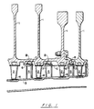
- Figure 1 illustrates a cross-section of a typical gas turbine engine.
- Figure 2 illustrates erosion rig test results.
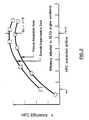
- FIG. 3 illustrates results of efficiency tests.
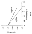
- Figure 4 illustrates the effect of permeability on efficiency.
- the present invention relates to seals having particular utility in gas turbine engines, particularly those of the axial flow type.
- gas turbine engines particularly those of the axial flow type.
- Such engines include alternate rows of stationary vanes and moving blades with the blades being attached at the periphery of shaft mounted rotating disks.
- Figure 1 illustrates a cross-section of a portion of a modern gas turbine engine.
- Components important to understanding the present invention include a plurality of rotatable disks 1 upon whose outer periphery are mounted a plurality of blades 2.
- the blades rotate within the inner case 3 and are closely spaced thereto.
- Minimum leakage between the blades and the inner case is achieved by the provision of a seal 4 (the outer air seal), mounted on the inner case.
- a plurality of vanes 5 mounted within and upon the inner case 3 are a plurality of vanes 5 on whose inner, free ends 6 is mounted another seal 7 (the inner air seal) which is closely spaced to knife edges 8 mounted on extensions of the disks 1.
- the knife edge 8 and inner air seal 7 cooperate to reduce leakage and improve efficiency.
- the disks do not have integral projections, but are separated by spacers upon which knife edges may be mounted.
- the abradable seals of the present invention are typically seal 4, located on the inner case 3 adjacent to the free ends of the blades 2 (the outer air seal), and seal 7, on the free ends 6 of the vanes 5 (the inner air seal).
- the seals of the present invention are preferably mounted on stationary substrates arranged to engage moving components.
- abradable seals for gas turbine engines include abradability, spall resistance, and erosion resistance.
- abradable seals due to increasing demand for improved performance, economy, and durability, abradable seals are also required to exhibit gas impermeability, smooth surface, and oxidation resistance at high temperatures.
- the seal is the sacrificial element, and it is desirable to minimize blade wear.
- Spallation resistance is desirable to eliminate domestic object damage, i.e. damage to the blades or other engine components by materials separated from internal surfaces.
- Erosion resistance is required to maintain clearances throughout the life of the engine, and thus maintain performance characteristics.
- Conventional commercial turbine engines have exhibited a two percent increase in air flow around bade tips as a result of seal erosion after approximately 3000 flights.
- oxidation resistance is required due to increases in compressor, operating temperatures, which are expected to reach 760°C [1400°F] to 871°C [1600°F] in the foreseeable future. Long term oxidation resistance also improves the erosion rate of abradable materials.
- the abradable seal of the present invention is applied by use of a plasma spray process, with plasma spray conditions preferably selected to proceed a high energy plasma spray to minimize porosity and control density, thereby essentially eliminating permeability.
- a multiple port plasma gun such as that shown in US-A- 4,696,855, is utilized. This gun allows injection of the matrix metal powder and the boron nitride powder at different points, thus permitting the metal to be in the plasma for a shorter period of time, while the more refractory boron nitride is in the plasma for a longer period of time.
- Use of a high energy plasma gun reduces coating porosity, to a level of preferably less than fifteen volume percent, and substantially increases erosion resistance and homogeneity.
- the flame sprayed process which has been used to apply abradable coatings in the prior art is a lower energy process which typically produces coatings with thirty to sixty volume percent porosity.
- the metal content of the coating prepared in accordance with the present invention is from about 50 to about 65 volume percent, and the coating has a bulk density greater than about 3.6 grams/cc, preferably from about 3.7 to about 5.3 grams/cc, and most preferably from about 3.8 to 5.2 grams/cc.
- Use of a multiple port plasma spray gun permits in situ mixing of the constituents of the abradable seal, and permits the seal material to be tailored to suit the engine application and environment. For example, in military engine applications, where gas path velocities are relatively high, erosion resistance is of paramount importance. Seal density, and thus erosion resistance and abradability, can be varied in situ by varying the ratio of constituents delivered to the plasma spray torch. Power input to the plasma torch may also be varied in situ to tailor seal properties. In general, erosion resistance may be increased by increasing inter-particulate bonding by increasing power levels. This, however, will decrease abradability.
- the use of independent powder injection and carrier gas flows for each constituent permits the component materials to be injected at optimal locations for their physical and thermal properties. High temperature refractory materials may be injected deep into the central core of the plasma, while less refractory materials may be injected into cooler regions, thus minimizing excess heating and thermal stress build-up in the coating.
- a key element in plasma spray technology is the interaction between the injected powder material and the plasma plume, in terms of heat transfer and dwell time.
- the optimal choice of coating parameters and injector configuration must be made. Particle distributions within the plasma jet are of particular importance due to effect upon coating density, quality, deposit efficiency, and reproducibility. It has been found that increasing the number of particle injection points into the plasma spray plume tends to increase the distribution of the particles in the central core of the plasma. and thus provide more uniform particle heating and dwell times. This is of particular importance when depositing relatively refractory materials, such as boron nitride. For the present invention, the maximum practical number of injection ports, three metallic and three boron nitride, has been utilized to take advantage of this phenomenon.
- ratios of constituent materials may be varied in situ makes this process suitable for automation and control by intelligent processing.
- In situ measurements of coating density by gamma back spatter or radiation attenuation may be fed to computer algorithms and a process controller to accomplish ration control.
- Automated measurement of thickness, such as by capacitance eddy current measurement, taken in conjunction with measurement of constituent flow, enables automatic determination of seal density, which may be established as the acceptance criteria.
- the plasma spray application of the metallic and boron nitride constituents may be carried out using conventional commercially available multiple port plasma spray torches.
- a multiple injection face plate incorporating three injection ports for the boron nitride and three injection ports for the metallic constituent is used.
- the face plate it is helpful for the face plate to incorporate automatic cleaning ports to inject air, or an inert gas, to periodically clean the powder ports. In this manner, the process was continued until the entire desired thickness of abradable was deposited.
- Spray processing may be achieved, with the application of material in excess of.254cm [0.100 inches] thick, using such apparatus, with acceptable thermal stress build-up and no seal spallation
- thermally sprayed seals of the past have improved initial performance
- the plasma sprayed seals of the present invention proved sustained performance benefits over the life to the engine.
- the seal density may be sued as the quality acceptance criteria, since this property correlates well to seal performance, provided that the plasma spray parameters are held within preset tolerance bands.
- seal density is by way of non-destructive gauge in which gamma radiation is passed through the abradable layer and the attenuation of the radiation intensity is measure and subsequently used to calculate seal density.
- a gauge is taught in US-A-4,783,341, issued November 8, 1988, to Janowsky et al.
- Destructive techniques such as ASTM C-20, may also be utilized to evaluate test tabs produced during a plasma spray operation.
- boron nitride is provided in the form of a powder having a particle size ranging from about 44 to 177 ⁇ m (microns), and the oxidation resistant metallic material is provided in the form of particles having particle size of from 44 to 150 ⁇ m(microns), preferably from 44 to 105 ⁇ m (microns).
- the boron nitride is a self-lubricating stable filler which is abradable, having a relatively soft crystalline structure, being a hexagonal material which shears readily.
- a permanent filler which is resistant to the environment encountered in a gas turbine engine, and which is thermally stable at temperatures up to about 871 °C [1600°F], boron nitride is present in a lubricating amount, preferably from about 20 to 45 volume percent of the abradable layer.
- the oxidation resistant matrix material must have a superior combination of mechanical properties at elevated temperature and resistance to oxidation at elevated temperatures. Creep strength at 649°C [1200°F] should be comparable to that of such superalloys designated in the industry as MarM 200, IN 100, Inconel 718, Waspaloy, Astroloy, Udimet 500, Hastaloy X, Inconel 625, and other alloys of like nature and composition.
- Suitable matrix metals include those nickel based superalloys having high oxidation resistance, preferably exceeding that of Nichrome at 649°C [1200°F], and particularly those which demonstrate oxidation resistance as a result of the addition of various combinations yttrium and hafnium. It has been found that benefits in terms of oxidation resistance may be achieved when yttrium is present within the range of from 0.001 to 0.8 weight percent, and hafnium is present in a range of from 0.10 to about 1.5 weight percent. Such materials exhibit resistance to rapid oxidation, i e do not ignite when exposed to severe rub conditions. Abradable seals of such material do not ignite titanium fires when interacting under severe conditions with blades prepared from titanium alloys.
- Suitable matrix materials having oxidation resistance exceeding that to nichrome at 649°C [1200°F] include the following alloys, as set forth in Table 1: SUITABLE MATRIX MATERIALS Alloy 1 Alloy 2 Alloy 3 min max min max min max Chromium 5.0 18.0 24.00 26.00 15.00 19.00 Aluminum 3.0 8.0 5.50 6.50 11.80 13.20 Hafnium 0.1 1.0 0.50 1.50 0.10 0.40 Yttrium 0.001 0.09 0.05 0.15 0.40 0.80 Titanium 0 5.0 - - - Cobalt 0 20.0 - - 20.00 24.00 Tungsten 0 15.0 7.50 8.50 - - Molybdenum 0 4.0 - - - Tantalum 0 12.0 3.50 4.50 - - Zirconium 0 0.2 - - - Boron 0 0.2 - - - Carbon 0 0.2 0.20 0.25 - 0.02 Silicon - - -
- oxidation resistant nickel base superalloys suitable for the present invention encompass a wide range of compositions inclusive of both hafnium and yttrium.
- the alloys may comprise 5 - 26 percent chromium, 3 - 13.2 percent aluminum, 0.1 - 1.5 percent hafnium, .001-0.80 percent yttrium, 0 - 5.0 percent titanium, 0 - 24.00 percent cobalt, 0 - 15.00 percent tungsten, 0 - 4.0 percent molybdenum, 0 - 12.0 percent tantalum, 0 - 0.2 percent zirconium, 0 - 0.2 percent boron, 0 - 0.25 percent carbon, 0 - 0.60 percent silicon, 0 - 7.0 percent rhenium, 0 - 5.0 percent columbium, 0 - 0.2 percent iron, 0 - 0. 1 percent copper, from 0-0.05 percent of each of phosphorous, sulfur, lead, bismuth, and manganese, and the balance
- the preferred matrix powders for plasma spraying are rapidly solidified nickel based superalloy powders having both yttrium and hafnium present, in suitable concentrations to achieve high oxidation resistance.
- the ratio of matrix metal to boron nitride in the abradable seal should fall within the range of 50 - 65 volume percent metal, 20 - 45 volume percent boron nitride, with 5 - 15 volume percent porosity, with the porosity being non-interconnected, thereby limiting permeability.
- the bulk density of the seal should be greater than about 3.6 grams/cc, preferably from about 3.7 to about 5.3 grams/cc, and most preferably from about 3.8 to about 5.2 grams/cc.
- Table II the content of boron nitride is given in volume percent for corresponding bulk densities and porosities.
- a non-abradable bond coat comprising an oxidation resistant metal is applied prior to the application of the abradable coating.
- this bond coat comprises the same metal as the matrix metal of the abradable layer, thus reducing galvanic corrosion activity between the bond coat and the abradable coating layer and is applied by plasma spraying.
- a typical bond coat thickness is from about .051mm [2] to about .508mm [20 mils], with a preferred thickness of from .178mm [7] to .305mm [12 mils].
- the bond coat is preferably of a density greater than 90 percent of theoretical, does not contain boron nitride, and exhibits low abradability relative to the boron nitride containing abradable layer.
- the particle size of the bond coat material may be the same as or of a larger size fraction than that of the abradable layer, so as to provide a rougher surface and a basis for greater adhesion of the abradable layer.
- the non-abradable bond coat is considered to be highly beneficial when applied to any metal substrate, and is particularly important and useful in the circumstance where the substrate being coated is titanium, since the bond coat also functions as a barrier layer, inhibiting penetration of the blade and preventing incursion into the titanium. It is critical to reduce the possibility of titanium contacting titanium since this is known to cause a substantial wear problem, and the possibility of sustained titanium combustion
- the metal substrate may be prepared for application of the plasma sprayed bond coat layer in known conventional manner.
- the abradable layer is applied, in a thickness of about .254mm [10] to about .508mm [200 mils], and preferably from about .508mm [20] to 2.54mm [100 mils].
- the coating may be stress relieved, for example at 578°C [1000] to 760°C [1400°F] for one to ten hours, preferably at 649°C [1200°F] for two to six hours, and machined to a surface roughness of less than 508 ⁇ m [200 microinches]
- a comparative example was conducted to evaluate the porosity of a flame sprayed coating with a plasma sprayed coating in accordance with the present invention.
- a high-porosity nickel-chromium-aluminum-boron nitride composite comprising Metco 301C-NS powder, used extensively for high temperature abradable coatings, was combustion sprayed onto a substrate to produce a Metco T301 coating, and subjected to measurement of porosity.
- the parameters and porosities of these coatings are as set forth in Table III, showing typical volume percentages.
- the coating of the present invention was considerably less porous.
- the flame spray composite was produced using a metal powder having the following composition specification (weight percent): Min Max Chromium 11.50 - 16.00 Iron 6.00 - 9.50 Boron Nitride 3.50 - 7.50 Aluminum 2.50 - 4.50 Silicon Dioxide ---- - 4.00 Organic Solids ---- - 4.00 Nickel 60.00 - ---- The particle size distribution (sieve size) was (+100), 1 percent maximum; (+120), 10.0 percent maximum; and (-325), 15 percent maximum.
- the composition of the matrix material used for the plasma sprayed coating was as follows: Min Max Chromium 8.0 - 10.0 Aluminum 6.6 - 7.0 Tungsten 9.0 - 10.0 Tantalum 2.5 - 3.5 Molybdenum 0.1 - 1.2 Hafnium 0.1 - 0.2 Yttrium 0.01 - 0.08 Carbon ---- - 0.02 Silicon ---- - 0.09 Phosphorous ---- - 0.005 Sulfur ---- - 0.005 Lead ---- - 2 ppm Bismuth ---- - 0.5 ppm Manganese ---- - 0.02 Iron ---- - 0.1 Copper ---- - 0.05 Nickel Balance
- the particle size distribution was (+140), 1 percent maximum: (+170), 7 percent maximum; (-170, +200), 38 - 48 percent; (-200, +230), 34 - 44 percent; (-230, +270), 10 - 20 percent: (-270), 4 percent maximum; and (-325), 1 percent maximum.
- the boron nitride component of the plasma sprayed coating comprised (weight percent): Min Max Boron Nitride 98.0 - ---- Oxygen ---- - 0.6 Carbon ---- - 0.2 Other impurities ---- - 0.3
- the particle size distribution (sieve size) of the boron nitride was (+80), 2 percent maximum; (-80, +200), 80 percent minimum; (-200, +325), 16 percent maximum; and (-325), 2 percent maximum.
- the boron nitnde comprised 47 volume percent of the plasma spray powder.
- the plasma sprayed coating was applied using a Metco 7 MB plasma spray gun, with a metal powder feed rate of 150 grams per minute and a boron nitride feed rate of 45 grams per minute.
- the current was set at 470 amps, with a voltage of 78 - 80 volts, using nitrogen as a primary gas at 33 ⁇ 3 SLP/M, and hydrogen as a secondary gas.
- the coating was applied to a thickness of about 2.92 mm [0 115 inches].
- Table IV illustrates blade tip rub results for boron nitride filled seals with different metal contents, made as set forth in Example I, with the addition of a bond coat of the matrix metal.
- the surface finish set forth is that of the rub zone.
- the Wear Index represents the average blade wear divided by the sum of rub depth and blade wear, whereby a lower value is to be preferred, and an index less than 0.1 is desired and less than 0.05 is preferred.
- the boron nitride lubricant filled seals of this invention were found to have equal or better abradability, as measured by wear index while the porous abradable seals were found to be unacceptable due to their lack of lubricity, which resulted in high temperature and seal cracking due to friction.
- the boron nitride lubricant of the present invention minimizes severe rub interactions which occur between blade tip and seal surface. Such interaction during certain engine operating conditions can significantly increase seal temperatures above ambient, which can cause cracking, glazing of the seal surface, or result in material transfer to the blade tip and subsequent seal spallation.
- plasma sprayed abradable seals of the present inventions have resulted in blade tip and seal temperatures up to 167°C [300°F] lower than tested against porous seals utilizing a comparable volume percentage of the same nickel alloy, as a result of reduced friction due to the presence of boron nitride, and increased thermal conductivity due to higher seal density
- Figure 2 illustrates the erosion resistance of the present invention
- Feltmetal® a commonly used porous seal material which comprises fibrous Haynes 188 cobalt based alloy, typically exhibits an erosion rate of from about 0.020 to about 0.065 cc/gram-of-erodant at a density of from about 1.6 to about 2.0 grams/cc, which parameters are outside the limits of this graph.
- a porous abradable seal made with Lucite® as a fugitive particulate in the same matrix metal employed in the present invention, typically exhibits an erosion rate of from about 0.020 to about 0.030 cc/gram-of-erodant at a density of from about 2.8 to about 3.5 grams/cc, which parameters are outside the limits of the graph.
- the present invention exhibits an erosion rate of less than 0.020 cc/gram-of-erodant, and preferably less than 0.010 cc/gram-of-erodant.
- the increased seal density of the seals containing particulate boron nitride lubricant provides additional erosion resistance compared to porous seals.
- Table V illustrates the surface roughness of a number of seals made as in Example 1 as compared to the surface roughness of the commercially available porous seal material.
- SURFACE ROUGHNESS ⁇ m/[MICROINCHES] Porous Seal Invention Range Average Range Average As Sprayed 2286-4064 [900-1600] 3175 [1250] 953-1575 [375-620] 1392 [548] Single Point Machined 1778-2286 [700-900] 2032 [800] 254-1524 [100-600] 381 [150]
- compressor seals prepared in accordance with this invention were fabricated and tested in a gas turbine engine to determine the benefits of smooth, impermeable seals.
- Back-to-back engine tests demonstrated a significant increase in compressor efficiency of one percent attributable to the present invention as compared to the use of rough, permeable compressor seals, as shown in Figure 3.
- Figure 3 illustrates the improved HPC efficiency (High Pressure Compressor efficiency) obtained when operating a smooth impermeable seal of the present invention, as compared to a conventional state-of-the-art porous abradable seal.
- HPC efficiency High Pressure Compressor efficiency
Landscapes
- Engineering & Computer Science (AREA)
- Chemical & Material Sciences (AREA)
- Mechanical Engineering (AREA)
- Plasma & Fusion (AREA)
- Chemical Kinetics & Catalysis (AREA)
- Materials Engineering (AREA)
- Physics & Mathematics (AREA)
- Metallurgy (AREA)
- Organic Chemistry (AREA)
- General Engineering & Computer Science (AREA)
- Coating By Spraying Or Casting (AREA)
- Turbine Rotor Nozzle Sealing (AREA)
- Other Surface Treatments For Metallic Materials (AREA)
Claims (21)
- Verbunddichtung für Gasturbinentriebwerke, welche umfaßt: a. ein metallisches Substrat;b. einen fest haftenden Haftüberzug auf dem Substrat, wobei der Haftüberzug eine niedrige Abschleifbarkeit zeigt und eine oxidationsbeständige Superlegierung umfaßt;c. eine homogene, abschleifbare Schicht, die über dem Haftüberzug plasmagespritzt ist, wobei die Schicht 50 bis 65 Volumenprozent oxidationsbeständige Superlegierung, 20 bis 45 Volumenprozent hexagonales Bornitrid und weniger als etwa 15 Volumenprozent Porosität aufweist und eine Oberflächenrauhigkeit von weniger als etwa 1524 µm hat.
- Verbunddichtung nach Anspruch 1, wobei die Superlegierung eine Nickelbasis-Superlegierung umfaßt, die Yttrium und Hafnium enthält, und gekennzeichnet ist durch eine Oxidationsbeständigkeit, die die von Nichrom bei 649 °C (1200 °F) übersteigt.
- Verbunddichtung nach Anspruch 2, wobei der Haftüberzug eine Dicke von 0,051 mm (2/1000) bis 0,508 mm (20/1000 Zoll) hat, auf das Substrat durch Plasmaspritzen aufgebracht ist und im wesentlichen aus derselben Superlegierung besteht, die in der abschleifbaren Schicht vorhanden ist.
- Verbunddichtung nach Anspruch 3; wobei die oxidationsbeständige Superlegierung umfaßt 5-26 Prozent Cr, 3-13,2 Prozent Al, 0,1-1,5 Prozent Hf, 0,001-0,80 Prozent Y, 0-5,0 Prozent Ti, 0-24 Prozenzt Co, 0-15 Prozent W, 0-4 Prozent Mo, 0-12 Prozent Ta, 0-0,2 Prozent Zr, 0-0,2 Prozent B, 0-0,25 Prozent C, 0-0,60 Prozent Si, 0-7,0 Prozent Re, 0-5,0 Prozent Nb, 0-0,2 Prozent Eisen, 0-0,1 Prozent Kupfer, 0-0,05 Prozent jeweils von Phosphor, Schwefel, Blei, Wismut und Mangan, Rest im wesentlichen Ni und Spurenelemente.
- Verbunddichtung nach Anspruch 4, wobei die Partikelgröße des Bornitrids vor dem Plasmaspritzen von 44-177 µm (Mikrometer) reicht.
- Verbunddichtung nach Anspruch 4, wobei die Partikelgröße der oxidationsbeständigen Legierung vor dem Plasmaspritzen von 44 bis 150 µm (Mikrometer) reicht.
- Verbunddichtung nach Anspruch 4, wobei die Dicke der abschleifbaren Schicht von 0,254 mm (10/1000) bis 5,08 mm (200/1000 Zoll) reicht.
- Verbunddichtung nach Anspruch 4, wobei die Porosität der abchleifbaren Schicht von 5-15 Volumenprozent reicht.
- Verbunddichtung nach Anspruch 8, wobei die Superlegierung umfaßt 5-18 Prozent Cr, 3-8 Prozent A1, 0,1-1,0 Prozent Hf, 0,001-0,09 Prozent Y, 0-5 Prozent Ti, 0-20 Prozent Co, 0-15 Prozent W, 0-4 Prozent Mo, 0-12 Prozent Ta, 0-0,2 Prozent Zr, 0-0,2 Prozent B, 0-0,2 Prozent C, 0-7 Prozent Re, 0-5 Prozent Nb, 3-9 Prozent (A1 + Ti), die Summe von (W + Ta + Mo + Nb + Re), die 5 Prozent übersteigt, und Rest Nickel.
- Verbunddichtung nach Anspruch 8, wobei die Superlegierung umfaßt 8,0-10,0 Prozent Cr, 6,6-7,0 Prozent Al, 9,0-10,0 Prozent W, 2,5-3,5 Prozent Ta, 0,1-1,2 Prozent Mo, 0,1-0,2 Prozent Hf, 0,01-0,08 Prozent Y, weniger als 0,02 Prozent C, weniger als 0,09 Prozent Si, weniger als 0,005 Prozent P, weniger als 0,005 Prozent S, weniger als 2 ppm Pb, weniger als 0,5 ppm Bi, weniger als 0,02 Prozent Mn, weniger als 0,1 Prozent Fe, weniger als 0,05 Prozent Cu, Rest Ni.
- Abschleifbare Verbunddichtung für Gasturbinentriebwerke nach Anspruch 1, wobei die Dichtung umfaßt:a. ein metallisches Substrat;b. einen fest haftenden Haftüberzug auf dem Substrat, der eine Dicke von 0,051 mm (2/1000) bis 0,508 mm (20/1000 Zoll) hat und im wesentlichen aus einer plasmagespritzten Nickelbasis-Superlegierung besteht, die eine Oxidationsbeständigkeit hat, welche die von Nichrom bei 649 °C (1200 °F) übersteigt; und eine plasmagespritzte, abschleifbare Schicht auf dem Haftüberzug, wobei die Schicht von 0,254 mm (10/1000) bis 5,08 mm (200/1000 Zoll) in der Dicke reicht und 50 bis 65 Volumenprozent Nickelbasis-Superlegierung enthält, eine Oxidationsbeständigkeit hat, die größer als die von Nichrom ist, und sowohl Yttrium als auch Hafnium enthält, 20 bis 45 Volumenprozent hexagonales Bornitrid enthält, weniger als etwa 15 Prozent Porosität und eine Oberflächenrauhigkeit, wie fabriziert, von weniger als etwa 1524 µm (600 Mikrozoll) hat.
- Abschleifbare Verbunddichtung für Gasturbinentriebwerke nach den Ansprüchen 1-11, wobei die abschleifbare Schicht einen Verschleißindex von weniger als 0,1 aufweist und durch Erosion eine Schichtabtragung von weniger als 0,020 cm3/g erfolgt.
- Abschleifbare Verbunddichtung für Gasturbinentriebwerke nach den Ansprüchen 1-11, wobei die abschleifbare Schicht eine Permeabilität von mehr als 20 Prozent und eine Fülldichte von mehr als 3,6 g/cm3 hat.
- Verfahren zum Herstellen einer abschleifbaren Dichtvorrichtung, wobei das Verfahren beinhalteta. Herrichten eines Substrats zum Auftragen eines Plasmaspritzüberzugs;b. Plasmaspritzen einer Haftüberzugsschicht niedriger Porosität auf das Substrat, die im wesentlichen aus einer Nickelbasis-Superlegierung besteht, welche eine Oxidationsbeständigkeit hat, die größer als die von Nichrom bei 649 °C (1200 °F) ist; undc. Plasmaspritzen einer abschleifbaren Schicht auf die Haftschicht, wobei die abschleifbare Schicht 50-65 Volumenprozent oxidationsbeständige Nickelbasis-Superlegierung und 20-45 Volumenprozent hexagonales Bornitrid umfaßt und weniger als 15 Volumenprozent Porosität aufweist.
- Verfahren nach Anspruch 14, wobei das Plasmaspritzen durch Plasmaspritzen mit mehreren Injektionsöffnungen erfolgt.
- Verfahren nach Anspruch 15, wobei unabhängige Pulverinjektions- und Trägergasströme für jeden Bestandteil der abschleifbaren Schicht benutzt werden.
- Verfahren nach Anspruch 16, wobei die Nickelbasis-Superlegierung, die sowohl in der Haftüberzugsschicht als auch in der abschleifbaren Schicht benutzt wird, umfaßt, nach Gewicht, 5-26 Prozent Cr, 3-13,2 Prozent Al, 0,1-1,5 Prozent Hf, 0,001-0,80 Prozent Y, 0-5,0 Prozent Ti, 0-24 Prozent Co, 0-15 Prozent W, 0-4 Prozent Mo, 0-12 Prozent Ta, 0-0,2 Prozent Zr, 0-0,2 Prozent B, 0-0,25 Prozent C, 0-0,60 Prozent Si, 0-7,0 Prozent Re, 0-5,0 Prozent Nb, 0-0,2 Prozent Eisen, 0-0,1 Prozent Kupfer, 0-0,05 Prozent jeweils von Phosphor, Schwefel, Blei, Wismut und Mangan, Rest im wesentlichen Ni und Spurenelemente.
- Verfahren nach Anspruch 17, wobei die Haftüberzugsschicht eine Dicke von 0,051 mm (2/1000) bis 0,508 mm (20/1000 Zoll) hat und wobei die abschleifbare Schicht eine Dicke von 0,254 mm (10/1000) bis 5,08 mm (200/1000 Zoll), eine Porosität von weniger als 15 Volumenprozent, eine Dichte von 3,7 bis 5,3 Gramm/cm3 und eine Oberflächenrauhigkeit, wie fabriziert, von weniger als 1524 µm (600 Mikrozoll) hat.
- Verfahren nach Anspruch 18, wobei die Dicke der Haftüberzugsschicht und die Dicke der abschleifbaren Schicht durch eine automatische Meßeinrichtung während des Auftragens gesteuert werden.
- Verfahren nach Anspruch 19, wobei die Bornitridpartikelgröße, vor dem Spritzen, von 44 bis 177 µm (Mikrometer) reicht, die Partikelgröße der oxidationsbeständigen Superlegierung, vor dem Spritzen, von 44 bis 150 µm (Mikrometer) reicht und drei Injektionsöffnungen für jede benutzt werden.
- Verfahren nach Anspruch 20, wobei die Superlegierung umfaßt, nach Gewicht, 8,0-10,0 Prozent Cr, 6,6-7,0 Prozent A1; 9,0-10,0 Prozent W, 2,5-3,5 Prozent Ta, 0,1-1,2 Prozent Mo, 0,1-02 Prozent Hf, 0,01-0,08 Prozent Y, weniger als 0,02 Prozent C, weniger als 0,09 Prozent Si, weniger als 0,005 Prozent P, weniger als 0,005 Prozent S, weniger als 2 ppm Pb, weniger als 0,5 ppm Bi, weniger als 0,02 Prozent Mn, weniger als 0,1 Prozent Fe, weniger als 0,05 Prozent Cu, Rest Ni.
Applications Claiming Priority (3)
| Application Number | Priority Date | Filing Date | Title |
|---|---|---|---|
| US08/145,896 US5536022A (en) | 1990-08-24 | 1993-10-29 | Plasma sprayed abradable seals for gas turbine engines |
| US145896 | 1993-10-29 | ||
| PCT/US1994/012431 WO1995012004A1 (en) | 1993-10-29 | 1994-10-28 | Plasma sprayed abradable seals for gas turbine engines |
Publications (2)
| Publication Number | Publication Date |
|---|---|
| EP0725842A1 EP0725842A1 (de) | 1996-08-14 |
| EP0725842B1 true EP0725842B1 (de) | 1998-01-07 |
Family
ID=22515026
Family Applications (1)
| Application Number | Title | Priority Date | Filing Date |
|---|---|---|---|
| EP95903101A Expired - Lifetime EP0725842B1 (de) | 1993-10-29 | 1994-10-28 | Abreibbare plasma gespritzte dichtungen für gasturbinen |
Country Status (5)
| Country | Link |
|---|---|
| US (2) | US5536022A (de) |
| EP (1) | EP0725842B1 (de) |
| JP (1) | JP3142003B2 (de) |
| DE (1) | DE69407811T2 (de) |
| WO (1) | WO1995012004A1 (de) |
Cited By (2)
| Publication number | Priority date | Publication date | Assignee | Title |
|---|---|---|---|---|
| US7165946B2 (en) | 2004-06-21 | 2007-01-23 | Solar Turbine Incorporated | Low-mid turbine temperature abradable coating |
| DE102013209189A1 (de) * | 2013-05-17 | 2014-11-20 | Siemens Aktiengesellschaft | Schutzbeschichtung und Gasturbinenkomponente mit der Schutzbeschichtung |
Families Citing this family (142)
| Publication number | Priority date | Publication date | Assignee | Title |
|---|---|---|---|---|
| US5660885A (en) * | 1995-04-03 | 1997-08-26 | General Electric Company | Protection of thermal barrier coating by a sacrificial surface coating |
| JP3258599B2 (ja) * | 1996-06-27 | 2002-02-18 | ユナイテッド テクノロジーズ コーポレイション | 断熱バリヤコーティングシステム |
| US5976695A (en) * | 1996-10-02 | 1999-11-02 | Westaim Technologies, Inc. | Thermally sprayable powder materials having an alloyed metal phase and a solid lubricant ceramic phase and abradable seal assemblies manufactured therefrom |
| US6355212B1 (en) * | 1997-07-10 | 2002-03-12 | Turbocoating Spa | Alloy for corrosion-resistant coatings or surface coatings |
| FR2768750B1 (fr) * | 1997-09-25 | 1999-11-05 | Snecma | Procede pour ameliorer la resistance a l'oxydation et a la corrosion d'une piece en superalliage et piece en superalliage obtenue par ce procede |
| US6332937B1 (en) * | 1997-09-25 | 2001-12-25 | Societe Nationale d'Etude et de Construction de Moteurs d'Aviation “SNECMA” | Method of improving oxidation and corrosion resistance of a superalloy article, and a superalloy article obtained by the method |
| US6190124B1 (en) | 1997-11-26 | 2001-02-20 | United Technologies Corporation | Columnar zirconium oxide abrasive coating for a gas turbine engine seal system |
| US5879753A (en) * | 1997-12-19 | 1999-03-09 | United Technologies Corporation | Thermal spray coating process for rotor blade tips using a rotatable holding fixture |
| US6180262B1 (en) | 1997-12-19 | 2001-01-30 | United Technologies Corporation | Thermal coating composition |
| NL1008103C2 (nl) * | 1998-01-23 | 1999-07-26 | Stichting Energie | Werkwijze voor het verbinden van een eerste object met een tweede object dat een deels open structuur vertoont. |
| SG72959A1 (en) | 1998-06-18 | 2000-05-23 | United Technologies Corp | Article having durable ceramic coating with localized abradable portion |
| US6761854B1 (en) * | 1998-09-04 | 2004-07-13 | Huntington Alloys Corporation | Advanced high temperature corrosion resistant alloy |
| US6089825A (en) | 1998-12-18 | 2000-07-18 | United Technologies Corporation | Abradable seal having improved properties and method of producing seal |
| US6203273B1 (en) * | 1998-12-22 | 2001-03-20 | United Technologies Corporation | Rotary machine |
| US6148518A (en) * | 1998-12-22 | 2000-11-21 | United Technologies Corporation | Method of assembling a rotary machine |
| US6165542A (en) * | 1998-12-23 | 2000-12-26 | United Technologies Corporation | Method for fabricating and inspecting coatings |
| JP2000192173A (ja) * | 1998-12-23 | 2000-07-11 | United Technol Corp <Utc> | 摩耗性材料および摩耗性被覆を有する金属製部品 |
| JP3897490B2 (ja) * | 1999-08-24 | 2007-03-22 | キヤノン株式会社 | 被覆ゴム部材、記録ヘッド、保管箱およびインクジェット記録装置 |
| SG88799A1 (en) | 1999-12-17 | 2002-05-21 | United Technologies Corp | Abradable seal having improved properties |
| US6352264B1 (en) | 1999-12-17 | 2002-03-05 | United Technologies Corporation | Abradable seal having improved properties |
| US6365236B1 (en) | 1999-12-20 | 2002-04-02 | United Technologies Corporation | Method for producing ceramic coatings containing layered porosity |
| JP4029375B2 (ja) * | 2000-06-21 | 2008-01-09 | スズキ株式会社 | 混合粉末溶射方法 |
| US6365222B1 (en) | 2000-10-27 | 2002-04-02 | Siemens Westinghouse Power Corporation | Abradable coating applied with cold spray technique |
| US6491208B2 (en) | 2000-12-05 | 2002-12-10 | Siemens Westinghouse Power Corporation | Cold spray repair process |
| JP4496650B2 (ja) * | 2001-01-10 | 2010-07-07 | 富士電機システムズ株式会社 | 蒸気タービン |
| US6444259B1 (en) | 2001-01-30 | 2002-09-03 | Siemens Westinghouse Power Corporation | Thermal barrier coating applied with cold spray technique |
| US6533285B2 (en) | 2001-02-05 | 2003-03-18 | Caterpillar Inc | Abradable coating and method of production |
| JP2002256808A (ja) * | 2001-02-28 | 2002-09-11 | Mitsubishi Heavy Ind Ltd | 燃焼エンジン、ガスタービン及び研磨層 |
| US7063250B2 (en) | 2001-05-31 | 2006-06-20 | Mitsubishi Heavy Industries, Ltd. | Coating forming method and coating forming material, and abrasive coating forming sheet |
| US6537021B2 (en) * | 2001-06-06 | 2003-03-25 | Chromalloy Gas Turbine Corporation | Abradeable seal system |
| US6688867B2 (en) | 2001-10-04 | 2004-02-10 | Eaton Corporation | Rotary blower with an abradable coating |
| CA2358624C (en) * | 2001-10-10 | 2009-12-22 | The Westaim Corporation | Sprayable composition |
| JP2003148103A (ja) | 2001-11-09 | 2003-05-21 | Mitsubishi Heavy Ind Ltd | タービンおよびその製造方法 |
| RU2302534C2 (ru) * | 2001-12-11 | 2007-07-10 | Альстом (Свитзерлэнд) Лтд. | Газотурбинное устройство |
| US20040005452A1 (en) * | 2002-01-14 | 2004-01-08 | Dorfman Mitchell R. | High temperature spray dried composite abradable powder for combustion spraying and abradable barrier coating produced using same |
| JP4267459B2 (ja) | 2002-02-28 | 2009-05-27 | コンセントラ マリーン アンド パワー アクツィエボラーグ | ピストンリングの溶射 |
| US6887530B2 (en) * | 2002-06-07 | 2005-05-03 | Sulzer Metco (Canada) Inc. | Thermal spray compositions for abradable seals |
| FR2840839B1 (fr) * | 2002-06-14 | 2005-01-14 | Snecma Moteurs | Materiau metallique susceptible d'etre use par abrasion; pieces, carter; procede d'elaboration dudit materiau |
| CN100430499C (zh) | 2002-08-16 | 2008-11-05 | 阿尔斯托姆科技有限公司 | 金属间材料及该材料的应用 |
| US6702553B1 (en) | 2002-10-03 | 2004-03-09 | General Electric Company | Abradable material for clearance control |
| US6969231B2 (en) * | 2002-12-31 | 2005-11-29 | General Electric Company | Rotary machine sealing assembly |
| US7645315B2 (en) * | 2003-01-13 | 2010-01-12 | Worldwide Strategy Holdings Limited | High-performance hardmetal materials |
| US20070034048A1 (en) * | 2003-01-13 | 2007-02-15 | Liu Shaiw-Rong S | Hardmetal materials for high-temperature applications |
| US6911063B2 (en) * | 2003-01-13 | 2005-06-28 | Genius Metal, Inc. | Compositions and fabrication methods for hardmetals |
| US6808756B2 (en) * | 2003-01-17 | 2004-10-26 | Sulzer Metco (Canada) Inc. | Thermal spray composition and method of deposition for abradable seals |
| US7207770B2 (en) * | 2003-05-27 | 2007-04-24 | General Electric Company | Variable stator vane bushings and washers |
| US20060029494A1 (en) * | 2003-05-27 | 2006-02-09 | General Electric Company | High temperature ceramic lubricant |
| US7220098B2 (en) * | 2003-05-27 | 2007-05-22 | General Electric Company | Wear resistant variable stator vane assemblies |
| US7094022B2 (en) * | 2003-05-27 | 2006-08-22 | General Electric Company | Variable stator vane bushings and washers |
| US7163369B2 (en) * | 2003-05-27 | 2007-01-16 | General Electric Company | Variable stator vane bushings and washers |
| US20050003097A1 (en) * | 2003-06-18 | 2005-01-06 | Siemens Westinghouse Power Corporation | Thermal spray of doped thermal barrier coating material |
| EP1536026A1 (de) * | 2003-11-27 | 2005-06-01 | Siemens Aktiengesellschaft | Hochtemperaturbeständiges Bauteil |
| DE10356953B4 (de) * | 2003-12-05 | 2016-01-21 | MTU Aero Engines AG | Einlaufbelag für Gasturbinen sowie Verfahren zur Herstellung desselben |
| US20050129868A1 (en) * | 2003-12-11 | 2005-06-16 | Siemens Westinghouse Power Corporation | Repair of zirconia-based thermal barrier coatings |
| KR20060044497A (ko) | 2004-03-23 | 2006-05-16 | 토소가부시키가이샤 | 내식성 부재 및 그 제조 방법 |
| US7857188B2 (en) * | 2005-03-15 | 2010-12-28 | Worldwide Strategy Holding Limited | High-performance friction stir welding tools |
| US20060219329A1 (en) * | 2005-03-29 | 2006-10-05 | Honeywell International, Inc. | Repair nickel-based superalloy and methods for refurbishment of gas turbine components |
| US20060219330A1 (en) * | 2005-03-29 | 2006-10-05 | Honeywell International, Inc. | Nickel-based superalloy and methods for repairing gas turbine components |
| US7543992B2 (en) * | 2005-04-28 | 2009-06-09 | General Electric Company | High temperature rod end bearings |
| KR100655366B1 (ko) | 2005-07-04 | 2006-12-08 | 한국과학기술연구원 | 내열, 내마모, 저마찰 특성을 가지는 코팅제 및 이의코팅방법 |
| US7322396B2 (en) * | 2005-10-14 | 2008-01-29 | General Electric Company | Weld closure of through-holes in a nickel-base superalloy hollow airfoil |
| DE102005058324A1 (de) * | 2005-12-07 | 2007-06-14 | Mtu Aero Engines Gmbh | Verfahren zum Herstellen eines Einlaufbelags |
| US7731809B2 (en) * | 2006-01-18 | 2010-06-08 | Honeywell International Inc. | Activated diffusion brazing alloys and repair process |
| US7985703B2 (en) | 2006-03-15 | 2011-07-26 | United Technologies Corporation | Wear-resistant coating |
| US7754350B2 (en) * | 2006-05-02 | 2010-07-13 | United Technologies Corporation | Wear-resistant coating |
| GB0610468D0 (en) * | 2006-05-26 | 2006-07-05 | Rolls Royce Plc | A method of manufacturing a component |
| RU2353779C2 (ru) * | 2007-02-19 | 2009-04-27 | Федеральное государственное унитарное предприятие "Московское машиностроительное производственное предприятие "Салют" | Прирабатываемое покрытие элемента турбомашины и способ его изготовления |
| US8038388B2 (en) * | 2007-03-05 | 2011-10-18 | United Technologies Corporation | Abradable component for a gas turbine engine |
| GB0705696D0 (en) * | 2007-03-24 | 2007-05-02 | Rolls Royce Plc | A method of repairing a damaged abradable coating |
| US20080260523A1 (en) * | 2007-04-18 | 2008-10-23 | Ioannis Alvanos | Gas turbine engine with integrated abradable seal |
| US20080260522A1 (en) * | 2007-04-18 | 2008-10-23 | Ioannis Alvanos | Gas turbine engine with integrated abradable seal and mount plate |
| US8530050B2 (en) * | 2007-05-22 | 2013-09-10 | United Technologies Corporation | Wear resistant coating |
| US7998604B2 (en) * | 2007-11-28 | 2011-08-16 | United Technologies Corporation | Article having composite layer |
| US20090162690A1 (en) * | 2007-12-24 | 2009-06-25 | Bangalore Aswatha Nagaraj | Thermal barrier coating systems |
| US20090162562A1 (en) * | 2007-12-24 | 2009-06-25 | Bangalore Aswatha Nagaraj | Methods for Applying Thermal Barrier Coating Systems |
| EP2100982A1 (de) * | 2008-03-03 | 2009-09-16 | Siemens Aktiengesellschaft | Gamma-Strich-verstärkte Superlegierung auf Nickelbasis |
| FR2935764B1 (fr) * | 2008-09-05 | 2014-06-13 | Snecma | Carter de compresseur resistant au feu de titane, compresseur haute pression comprenant un tel carter et moteur d'aeronef equipe d'un tel compresseur |
| US20100124616A1 (en) * | 2008-11-19 | 2010-05-20 | General Electric Company | Method of forming an abradable coating |
| US8273148B2 (en) * | 2009-01-30 | 2012-09-25 | Untied Technologies Corporation | Nickel braze alloy composition |
| US8172519B2 (en) * | 2009-05-06 | 2012-05-08 | General Electric Company | Abradable seals |
| CN101921979B (zh) * | 2009-06-10 | 2012-12-12 | 沈阳黎明航空发动机(集团)有限责任公司 | 一种等离子喷涂制备封严涂层的方法 |
| US20110309585A1 (en) * | 2009-06-16 | 2011-12-22 | Hidekazu Uehara | Shaft seal device |
| JP5210984B2 (ja) * | 2009-06-29 | 2013-06-12 | 株式会社日立製作所 | タービン用高信頼性メタルシール材 |
| US20110027573A1 (en) * | 2009-08-03 | 2011-02-03 | United Technologies Corporation | Lubricated Abradable Coating |
| US8236163B2 (en) * | 2009-09-18 | 2012-08-07 | United Technologies Corporation | Anode media for use in electroplating processes, and methods of cleaning thereof |
| US20110086163A1 (en) * | 2009-10-13 | 2011-04-14 | Walbar Inc. | Method for producing a crack-free abradable coating with enhanced adhesion |
| DE102009055914A1 (de) * | 2009-11-27 | 2011-06-09 | Rolls-Royce Deutschland Ltd & Co Kg | Dichtringe für eine Labyrinthdichtung |
| RU2424874C1 (ru) * | 2009-12-14 | 2011-07-27 | Общество с ограниченной ответственностью "Научно-производственное предприятие Вакууммаш" | Элемент прирабатываемого уплотнения турбины |
| EP2374909B1 (de) * | 2010-03-30 | 2015-09-16 | United Technologies Corporation | Verbesserte Nickellötlegierungszusammensetzung |
| US9598972B2 (en) | 2010-03-30 | 2017-03-21 | United Technologies Corporation | Abradable turbine air seal |
| US8562290B2 (en) | 2010-04-01 | 2013-10-22 | United Technologies Corporation | Blade outer air seal with improved efficiency |
| US20110256421A1 (en) * | 2010-04-16 | 2011-10-20 | United Technologies Corporation | Metallic coating for single crystal alloys |
| US8790078B2 (en) | 2010-10-25 | 2014-07-29 | United Technologies Corporation | Abrasive rotor shaft ceramic coating |
| US9169740B2 (en) | 2010-10-25 | 2015-10-27 | United Technologies Corporation | Friable ceramic rotor shaft abrasive coating |
| US8770927B2 (en) | 2010-10-25 | 2014-07-08 | United Technologies Corporation | Abrasive cutter formed by thermal spray and post treatment |
| US8770926B2 (en) | 2010-10-25 | 2014-07-08 | United Technologies Corporation | Rough dense ceramic sealing surface in turbomachines |
| US8936432B2 (en) | 2010-10-25 | 2015-01-20 | United Technologies Corporation | Low density abradable coating with fine porosity |
| GB2489693B (en) | 2011-04-04 | 2014-10-01 | Rolls Royce Plc | Abradable liner |
| RU2461448C1 (ru) * | 2011-05-27 | 2012-09-20 | Общество с ограниченной ответственностью "Научно-производственное предприятие Вакууммаш" | Способ изготовления прирабатываемого уплотнения турбины со столбчатой структурой |
| RU2457071C1 (ru) * | 2011-05-31 | 2012-07-27 | Общество с ограниченной ответственностью "Научно-производственное предприятие Вакууммаш" | Способ изготовления прирабатываемого уплотнения турбины с ориентированной структурой |
| RU2461449C1 (ru) * | 2011-06-27 | 2012-09-20 | Общество с ограниченной ответственностью "Научно-производственное предприятие Вакууммаш" | Способ изготовления прирабатываемого уплотнения турбины с многослойной оболочкой |
| US8876470B2 (en) | 2011-06-29 | 2014-11-04 | United Technologies Corporation | Spall resistant abradable turbine air seal |
| RU2478454C1 (ru) * | 2011-07-28 | 2013-04-10 | Общество с ограниченной ответственностью "Научно-производственное предприятие Вакууммаш" | Способ изготовления прирабатываемого уплотнения турбомашины |
| US8777562B2 (en) | 2011-09-27 | 2014-07-15 | United Techologies Corporation | Blade air seal with integral barrier |
| RU2499143C2 (ru) * | 2012-02-29 | 2013-11-20 | Общество с ограниченной ответственностью "Научно-производственное предприятие Вакууммаш" | Надбандажное прирабатываемое уплотнение для паровой турбины |
| RU2509896C1 (ru) * | 2012-08-01 | 2014-03-20 | Общество с ограниченной ответственностью "Научно-производственное предприятие Вакууммаш" | Надбандажное лабиринтное уплотнение для паровой турбины |
| FR2994397B1 (fr) * | 2012-08-07 | 2014-08-01 | Snecma | Revetement en materiau abradable a faible rugosite de surface |
| DE102012107499A1 (de) * | 2012-08-16 | 2014-05-22 | Dr. Ing. H.C. F. Porsche Aktiengesellschaft | Verfahren zur Beschichtung |
| DE102013002483B4 (de) * | 2013-02-14 | 2019-02-21 | Vdm Metals International Gmbh | Nickel-Kobalt-Legierung |
| EP2964807B1 (de) | 2013-03-07 | 2019-08-07 | United Technologies Corporation | Turbinentriebwerkskomponente enthaltend eine leichte und korrosionsbeständige abreibbare beschichtung |
| DE102013218687A1 (de) * | 2013-09-18 | 2015-04-02 | MTU Aero Engines AG | Galvanisch hergestellte Verschleißschutzbeschichtung und Verfahren hierfür |
| EP3055445B1 (de) * | 2013-10-09 | 2020-01-22 | United Technologies Corporation | Aluminiumlegierungsbeschichtung mit seltenen erden und übergangsmetall-korrosionsinhibitoren |
| EP3068997B1 (de) | 2013-11-11 | 2021-12-29 | Raytheon Technologies Corporation | Segmentierte dichtung für gasturbinenmotor |
| US10247026B2 (en) * | 2013-11-20 | 2019-04-02 | United Technologies Corporation | Erosion resistant coating for air seal |
| US10513942B2 (en) | 2013-12-10 | 2019-12-24 | United Technologies Corporation | Fusible bond for gas turbine engine coating system |
| CN104385703B (zh) * | 2014-11-20 | 2016-06-08 | 西安交通大学 | 一种叶片表面修复的复合梯度涂层及其制备方法 |
| EP3023511B1 (de) * | 2014-11-24 | 2021-07-28 | Safran Aero Boosters SA | Zusammensetzung und Abriebdichtung eines Kompressorgehäuses einer axialen Turbomaschine |
| US10060281B2 (en) * | 2014-12-29 | 2018-08-28 | United Technologies Corporation | Compressor abradable material seal with tailored wear ratio and desirable erosion resistance |
| US10634055B2 (en) | 2015-02-05 | 2020-04-28 | United Technologies Corporation | Gas turbine engine having section with thermally isolated area |
| US9920652B2 (en) | 2015-02-09 | 2018-03-20 | United Technologies Corporation | Gas turbine engine having section with thermally isolated area |
| US9896756B2 (en) * | 2015-06-02 | 2018-02-20 | United Technologies Corporation | Abradable seal and method of producing a seal |
| US10669878B2 (en) | 2016-03-23 | 2020-06-02 | Raytheon Technologies Corporation | Outer airseal abradable rub strip |
| JP6457420B2 (ja) * | 2016-03-31 | 2019-01-23 | トヨタ自動車株式会社 | 溶射用粉末およびこれを用いたアブレーダブル溶射皮膜の成膜方法 |
| US10408074B2 (en) | 2016-04-25 | 2019-09-10 | United Technologies Corporation | Creep resistant axial ring seal |
| US10267174B2 (en) | 2016-04-28 | 2019-04-23 | United Technologies Corporation | Outer airseal abradable rub strip |
| US10315249B2 (en) | 2016-07-29 | 2019-06-11 | United Technologies Corporation | Abradable material feedstock and methods and apparatus for manufacture |
| DE102016221470A1 (de) * | 2016-11-02 | 2018-05-03 | Siemens Aktiengesellschaft | Superlegierung ohne Titan, Pulver, Verfahren und Bauteil |
| US11225878B1 (en) | 2016-12-21 | 2022-01-18 | Technetics Group Llc | Abradable composite material and method of making the same |
| JP6855891B2 (ja) * | 2017-04-13 | 2021-04-07 | トヨタ自動車株式会社 | 溶射用粉末およびこれを用いた溶射皮膜の成膜方法 |
| US10294962B2 (en) | 2017-06-30 | 2019-05-21 | United Technologies Corporation | Turbine engine seal for high erosion environment |
| CN107841705B (zh) * | 2017-11-09 | 2019-03-19 | 深圳臻金精密科技有限公司 | 一种制备抗氧化耐高温金属涂层的方法 |
| US10954820B2 (en) * | 2018-01-31 | 2021-03-23 | Pratt & Whitney Canada Corp. | Non-contacting seal with non-abradable coating |
| US10815783B2 (en) * | 2018-05-24 | 2020-10-27 | General Electric Company | In situ engine component repair |
| CA3129143A1 (en) * | 2019-03-07 | 2020-09-10 | Oerlikon Metco (Us) Inc. | Advanced bond coat materials for tbc with improved thermal cyclic fatigue and sulfidation resistance |
| EP3990768A4 (de) * | 2019-06-26 | 2023-07-26 | Quantum Industrial Development Corp. | Externer verbrennungsmotortreibgaskreislauf für kraftfahrzeuge und industrielle anwendungen |
| FR3099187B1 (fr) * | 2019-07-26 | 2023-05-26 | Safran Aircraft Engines | Revêtement abradable |
| US11686208B2 (en) | 2020-02-06 | 2023-06-27 | Rolls-Royce Corporation | Abrasive coating for high-temperature mechanical systems |
| FR3107298B1 (fr) * | 2020-02-18 | 2022-02-04 | Safran Aircraft Engines | Turbine comportant un espace secondaire interne équipé d’ailettes de correction de giration d’un flux d’air |
| FR3107524B1 (fr) * | 2020-02-25 | 2022-12-16 | Safran Aircraft Engines | Revêtement abradable |
| US11426822B2 (en) * | 2020-12-03 | 2022-08-30 | General Electric Company | Braze composition and process of using |
| CN115233074A (zh) * | 2022-07-12 | 2022-10-25 | 北京科技大学 | 一种燃机动叶片用钴镍基高温合金及其制备方法 |
| CN115627445B (zh) * | 2022-12-22 | 2023-03-28 | 爱柯迪股份有限公司 | 一种铝压铸模具抗黏附高熵硼化物复合涂层及其制备方法 |
Family Cites Families (15)
| Publication number | Priority date | Publication date | Assignee | Title |
|---|---|---|---|---|
| US3084064A (en) * | 1959-08-06 | 1963-04-02 | Union Carbide Corp | Abradable metal coatings and process therefor |
| US3879831A (en) * | 1971-11-15 | 1975-04-29 | United Aircraft Corp | Nickle base high temperature abradable material |
| US4039296A (en) * | 1975-12-12 | 1977-08-02 | General Electric Company | Clearance control through a Ni-graphite/NiCr-base alloy powder mixture |
| US4743514A (en) * | 1983-06-29 | 1988-05-10 | Allied-Signal Inc. | Oxidation resistant protective coating system for gas turbine components, and process for preparation of coated components |
| US4664973A (en) * | 1983-12-27 | 1987-05-12 | United Technologies Corporation | Porous metal abradable seal material |
| EP0187612B1 (de) * | 1984-12-24 | 1990-09-12 | United Technologies Corporation | Abschleifbare Dichtung mit besonderem Erosionswiderstand |
| DD243514B1 (de) * | 1985-12-17 | 1989-04-26 | Karl Marx Stadt Tech Hochschul | Hartstoffschichten fuer mechanisch und korrosiv beanspruchte teile |
| US4696855A (en) * | 1986-04-28 | 1987-09-29 | United Technologies Corporation | Multiple port plasma spray apparatus and method for providing sprayed abradable coatings |
| US4783341A (en) * | 1987-05-04 | 1988-11-08 | United Technologies Corporation | Method and apparatus for measuring the density and hardness of porous plasma sprayed coatings |
| DE3734768A1 (de) * | 1987-10-14 | 1989-05-03 | Battelle Institut E V | Armaturteil zum einsatz in einem schwefelsauren medium, das auch abrasiv wirkende feststoffteilchen enthaelt und verfahren zur herstellung eines solchen armaturteiles |
| JPH01242786A (ja) * | 1988-03-23 | 1989-09-27 | Mitsubishi Heavy Ind Ltd | 摺動部材及びその製造方法 |
| US4936745A (en) * | 1988-12-16 | 1990-06-26 | United Technologies Corporation | Thin abradable ceramic air seal |
| JPH0396601A (ja) * | 1989-09-08 | 1991-04-22 | Toyota Motor Corp | 相対移動装置 |
| US5122182A (en) * | 1990-05-02 | 1992-06-16 | The Perkin-Elmer Corporation | Composite thermal spray powder of metal and non-metal |
| US5302450A (en) * | 1993-07-06 | 1994-04-12 | Ford Motor Company | Metal encapsulated solid lubricant coating system |
-
1993
- 1993-10-29 US US08/145,896 patent/US5536022A/en not_active Expired - Lifetime
-
1994
- 1994-10-28 WO PCT/US1994/012431 patent/WO1995012004A1/en not_active Ceased
- 1994-10-28 EP EP95903101A patent/EP0725842B1/de not_active Expired - Lifetime
- 1994-10-28 DE DE69407811T patent/DE69407811T2/de not_active Expired - Lifetime
- 1994-10-28 JP JP07512869A patent/JP3142003B2/ja not_active Expired - Fee Related
-
1997
- 1997-05-27 US US08/863,414 patent/US5780116A/en not_active Expired - Lifetime
Cited By (2)
| Publication number | Priority date | Publication date | Assignee | Title |
|---|---|---|---|---|
| US7165946B2 (en) | 2004-06-21 | 2007-01-23 | Solar Turbine Incorporated | Low-mid turbine temperature abradable coating |
| DE102013209189A1 (de) * | 2013-05-17 | 2014-11-20 | Siemens Aktiengesellschaft | Schutzbeschichtung und Gasturbinenkomponente mit der Schutzbeschichtung |
Also Published As
| Publication number | Publication date |
|---|---|
| JPH09504340A (ja) | 1997-04-28 |
| DE69407811T2 (de) | 1998-04-23 |
| US5780116A (en) | 1998-07-14 |
| EP0725842A1 (de) | 1996-08-14 |
| WO1995012004A1 (en) | 1995-05-04 |
| JP3142003B2 (ja) | 2001-03-07 |
| US5536022A (en) | 1996-07-16 |
| DE69407811D1 (de) | 1998-02-12 |
Similar Documents
| Publication | Publication Date | Title |
|---|---|---|
| US5536022A (en) | Plasma sprayed abradable seals for gas turbine engines | |
| US4275124A (en) | Carbon bearing MCrAlY coating | |
| US4275090A (en) | Process for carbon bearing MCrAlY coating | |
| US5976695A (en) | Thermally sprayable powder materials having an alloyed metal phase and a solid lubricant ceramic phase and abradable seal assemblies manufactured therefrom | |
| EP1509631B1 (de) | Thermische sprühbeschichtungszusammensetzungen für abschleifbare dichtungen | |
| US5622638A (en) | Method for forming an environmentally resistant blade tip | |
| US7052527B2 (en) | Thermal spray composition and method of deposition for abradable seals | |
| US3961910A (en) | Rhodium-containing superalloy coatings and methods of making same | |
| US5104293A (en) | Method for applying abrasive layers to blade surfaces | |
| EP0270785B1 (de) | Verschleisskörper und Pulver sowie Verfahren zur Herstellung | |
| JPS6136061B2 (de) | ||
| EP1103628A2 (de) | Beschichtungssystem zur Herstellung einer umweltschützenden Beschichtung auf ein Metallsubstrat | |
| US20180347390A1 (en) | Turbine Clearance Control Coatings and Method | |
| EP0816526B1 (de) | Isolierendes, wärmedämmendes Beschichtungssystem | |
| EP1254968A1 (de) | Materialbehandlung für verminderte Schneidenergie und verbesserte Temperaturkapazität von Honigwabendichtungen | |
| CA2048804A1 (en) | Long life abrasive turbine blade tips | |
| US4937042A (en) | Method for making an abradable article | |
| US6434876B1 (en) | Method of applying a particle-embedded coating to a substrate | |
| JPH0555295B2 (de) | ||
| CA1168477A (en) | Oxidation and wear resistant coated article | |
| EP2432912B1 (de) | VERFAHREN ZUR HERSTELLUNG & xA;EINER MIT REAKTIVEN ELEMENTEN - MODIFIZIERTEN ALUMINID BESCHICHTUNG DURCH DIFFUSIONSVERFAHREN IN DER DAMPFPHASE | |
| US3545944A (en) | Composite metal article having an intermediate bonding layer of nickel aluminide | |
| US3573963A (en) | Method of coating nickel base alloys with a mixture of tungsten and aluminum powders | |
| US5226977A (en) | Method of hardfacing an engine valve of a titanium material | |
| US3413136A (en) | Abradable coating |
Legal Events
| Date | Code | Title | Description |
|---|---|---|---|
| PUAI | Public reference made under article 153(3) epc to a published international application that has entered the european phase |
Free format text: ORIGINAL CODE: 0009012 |
|
| 17P | Request for examination filed |
Effective date: 19960404 |
|
| AK | Designated contracting states |
Kind code of ref document: A1 Designated state(s): DE FR GB |
|
| 17Q | First examination report despatched |
Effective date: 19960910 |
|
| GRAG | Despatch of communication of intention to grant |
Free format text: ORIGINAL CODE: EPIDOS AGRA |
|
| GRAG | Despatch of communication of intention to grant |
Free format text: ORIGINAL CODE: EPIDOS AGRA |
|
| GRAH | Despatch of communication of intention to grant a patent |
Free format text: ORIGINAL CODE: EPIDOS IGRA |
|
| GRAH | Despatch of communication of intention to grant a patent |
Free format text: ORIGINAL CODE: EPIDOS IGRA |
|
| GRAA | (expected) grant |
Free format text: ORIGINAL CODE: 0009210 |
|
| AK | Designated contracting states |
Kind code of ref document: B1 Designated state(s): DE FR GB |
|
| ET | Fr: translation filed | ||
| REF | Corresponds to: |
Ref document number: 69407811 Country of ref document: DE Date of ref document: 19980212 |
|
| PLBE | No opposition filed within time limit |
Free format text: ORIGINAL CODE: 0009261 |
|
| STAA | Information on the status of an ep patent application or granted ep patent |
Free format text: STATUS: NO OPPOSITION FILED WITHIN TIME LIMIT |
|
| 26N | No opposition filed | ||
| REG | Reference to a national code |
Ref country code: GB Ref legal event code: IF02 |
|
| PGFP | Annual fee paid to national office [announced via postgrant information from national office to epo] |
Ref country code: FR Payment date: 20081006 Year of fee payment: 15 |
|
| REG | Reference to a national code |
Ref country code: FR Ref legal event code: ST Effective date: 20100630 |
|
| PG25 | Lapsed in a contracting state [announced via postgrant information from national office to epo] |
Ref country code: FR Free format text: LAPSE BECAUSE OF NON-PAYMENT OF DUE FEES Effective date: 20091102 |
|
| PGFP | Annual fee paid to national office [announced via postgrant information from national office to epo] |
Ref country code: GB Payment date: 20131023 Year of fee payment: 20 Ref country code: DE Payment date: 20131023 Year of fee payment: 20 |
|
| REG | Reference to a national code |
Ref country code: DE Ref legal event code: R071 Ref document number: 69407811 Country of ref document: DE |
|
| REG | Reference to a national code |
Ref country code: GB Ref legal event code: PE20 Expiry date: 20141027 |
|
| PG25 | Lapsed in a contracting state [announced via postgrant information from national office to epo] |
Ref country code: GB Free format text: LAPSE BECAUSE OF EXPIRATION OF PROTECTION Effective date: 20141027 |