EP0726186A1 - Verankerungsvorrichtung für einen sicherheitsgurt und verfahren zu ihrer herstellung - Google Patents
Verankerungsvorrichtung für einen sicherheitsgurt und verfahren zu ihrer herstellung Download PDFInfo
- Publication number
- EP0726186A1 EP0726186A1 EP95929244A EP95929244A EP0726186A1 EP 0726186 A1 EP0726186 A1 EP 0726186A1 EP 95929244 A EP95929244 A EP 95929244A EP 95929244 A EP95929244 A EP 95929244A EP 0726186 A1 EP0726186 A1 EP 0726186A1
- Authority
- EP
- European Patent Office
- Prior art keywords
- belt
- long edge
- edge part
- protrusion
- shaped member
- Prior art date
- Legal status (The legal status is an assumption and is not a legal conclusion. Google has not performed a legal analysis and makes no representation as to the accuracy of the status listed.)
- Granted
Links
Images









Classifications
-
- B—PERFORMING OPERATIONS; TRANSPORTING
- B60—VEHICLES IN GENERAL
- B60R—VEHICLES, VEHICLE FITTINGS, OR VEHICLE PARTS, NOT OTHERWISE PROVIDED FOR
- B60R22/00—Safety belts or body harnesses in vehicles
- B60R22/34—Belt retractors, e.g. reels
- B60R22/44—Belt retractors, e.g. reels with means for reducing belt tension during use under normal conditions
-
- B—PERFORMING OPERATIONS; TRANSPORTING
- B21—MECHANICAL METAL-WORKING WITHOUT ESSENTIALLY REMOVING MATERIAL; PUNCHING METAL
- B21C—MANUFACTURE OF METAL SHEETS, WIRE, RODS, TUBES, PROFILES OR LIKE SEMI-MANUFACTURED PRODUCTS OTHERWISE THAN BY ROLLING; AUXILIARY OPERATIONS USED IN CONNECTION WITH METAL-WORKING WITHOUT ESSENTIALLY REMOVING MATERIAL
- B21C37/00—Manufacture of metal sheets, rods, wire, tubes, profiles or like semi-manufactured products, not otherwise provided for; Manufacture of tubes of special shape
- B21C37/06—Manufacture of metal sheets, rods, wire, tubes, profiles or like semi-manufactured products, not otherwise provided for; Manufacture of tubes of special shape of tubes or metal hoses; Combined procedures for making tubes, e.g. for making multi-wall tubes
- B21C37/15—Making tubes of special shape; Making tube fittings
- B21C37/28—Making tube fittings for connecting pipes, e.g. U-pieces
- B21C37/29—Making branched pieces, e.g. T-pieces
- B21C37/292—Forming collars by drawing or pushing a rigid forming tool through an opening in the tube wall
-
- B—PERFORMING OPERATIONS; TRANSPORTING
- B21—MECHANICAL METAL-WORKING WITHOUT ESSENTIALLY REMOVING MATERIAL; PUNCHING METAL
- B21D—WORKING OR PROCESSING OF SHEET METAL OR METAL TUBES, RODS OR PROFILES WITHOUT ESSENTIALLY REMOVING MATERIAL; PUNCHING METAL
- B21D22/00—Shaping without cutting, by stamping, spinning, or deep-drawing
- B21D22/02—Stamping using rigid devices or tools
- B21D22/04—Stamping using rigid devices or tools for dimpling
-
- B—PERFORMING OPERATIONS; TRANSPORTING
- B21—MECHANICAL METAL-WORKING WITHOUT ESSENTIALLY REMOVING MATERIAL; PUNCHING METAL
- B21K—MAKING FORGED OR PRESSED METAL PRODUCTS, e.g. HORSE-SHOES, RIVETS, BOLTS OR WHEELS
- B21K1/00—Making machine elements
- B21K1/28—Making machine elements wheels; discs
-
- B—PERFORMING OPERATIONS; TRANSPORTING
- B21—MECHANICAL METAL-WORKING WITHOUT ESSENTIALLY REMOVING MATERIAL; PUNCHING METAL
- B21K—MAKING FORGED OR PRESSED METAL PRODUCTS, e.g. HORSE-SHOES, RIVETS, BOLTS OR WHEELS
- B21K1/00—Making machine elements
- B21K1/76—Making machine elements elements not mentioned in one of the preceding groups
-
- B—PERFORMING OPERATIONS; TRANSPORTING
- B21—MECHANICAL METAL-WORKING WITHOUT ESSENTIALLY REMOVING MATERIAL; PUNCHING METAL
- B21K—MAKING FORGED OR PRESSED METAL PRODUCTS, e.g. HORSE-SHOES, RIVETS, BOLTS OR WHEELS
- B21K23/00—Making other articles
- B21K23/04—Making other articles flanged articles
-
- B—PERFORMING OPERATIONS; TRANSPORTING
- B60—VEHICLES IN GENERAL
- B60R—VEHICLES, VEHICLE FITTINGS, OR VEHICLE PARTS, NOT OTHERWISE PROVIDED FOR
- B60R21/00—Arrangements or fittings on vehicles for protecting or preventing injuries to occupants or pedestrians in case of accidents or other traffic risks
- B60R21/02—Occupant safety arrangements or fittings, e.g. crash pads
- B60R21/16—Inflatable occupant restraints or confinements designed to inflate upon impact or impending impact, e.g. air bags
- B60R21/18—Inflatable occupant restraints or confinements designed to inflate upon impact or impending impact, e.g. air bags the inflatable member formed as a belt or harness or combined with a belt or harness arrangement
-
- B—PERFORMING OPERATIONS; TRANSPORTING
- B60—VEHICLES IN GENERAL
- B60R—VEHICLES, VEHICLE FITTINGS, OR VEHICLE PARTS, NOT OTHERWISE PROVIDED FOR
- B60R22/00—Safety belts or body harnesses in vehicles
- B60R22/18—Anchoring devices
-
- B—PERFORMING OPERATIONS; TRANSPORTING
- B60—VEHICLES IN GENERAL
- B60R—VEHICLES, VEHICLE FITTINGS, OR VEHICLE PARTS, NOT OTHERWISE PROVIDED FOR
- B60R22/00—Safety belts or body harnesses in vehicles
- B60R22/18—Anchoring devices
- B60R22/24—Anchoring devices secured to the side, door, or roof of the vehicle
-
- Y—GENERAL TAGGING OF NEW TECHNOLOGICAL DEVELOPMENTS; GENERAL TAGGING OF CROSS-SECTIONAL TECHNOLOGIES SPANNING OVER SEVERAL SECTIONS OF THE IPC; TECHNICAL SUBJECTS COVERED BY FORMER USPC CROSS-REFERENCE ART COLLECTIONS [XRACs] AND DIGESTS
- Y10—TECHNICAL SUBJECTS COVERED BY FORMER USPC
- Y10T—TECHNICAL SUBJECTS COVERED BY FORMER US CLASSIFICATION
- Y10T29/00—Metal working
- Y10T29/49—Method of mechanical manufacture
- Y10T29/49616—Structural member making
- Y10T29/49622—Vehicular structural member making
-
- Y—GENERAL TAGGING OF NEW TECHNOLOGICAL DEVELOPMENTS; GENERAL TAGGING OF CROSS-SECTIONAL TECHNOLOGIES SPANNING OVER SEVERAL SECTIONS OF THE IPC; TECHNICAL SUBJECTS COVERED BY FORMER USPC CROSS-REFERENCE ART COLLECTIONS [XRACs] AND DIGESTS
- Y10—TECHNICAL SUBJECTS COVERED BY FORMER USPC
- Y10T—TECHNICAL SUBJECTS COVERED BY FORMER US CLASSIFICATION
- Y10T29/00—Metal working
- Y10T29/49—Method of mechanical manufacture
- Y10T29/49995—Shaping one-piece blank by removing material
-
- Y—GENERAL TAGGING OF NEW TECHNOLOGICAL DEVELOPMENTS; GENERAL TAGGING OF CROSS-SECTIONAL TECHNOLOGIES SPANNING OVER SEVERAL SECTIONS OF THE IPC; TECHNICAL SUBJECTS COVERED BY FORMER USPC CROSS-REFERENCE ART COLLECTIONS [XRACs] AND DIGESTS
- Y10—TECHNICAL SUBJECTS COVERED BY FORMER USPC
- Y10T—TECHNICAL SUBJECTS COVERED BY FORMER US CLASSIFICATION
- Y10T83/00—Cutting
- Y10T83/04—Processes
- Y10T83/06—Blanking
Definitions
- a belt mounting clamp comprises a base (plate shaped member) 2 having a bolt hole 3 and a slot 69 formed thereon and is designed to be secured to a fixed part such as a vehicle body through the belt hole 3 and to be connected to a belt 13 through the slot 69.
- the above mentioned conventional belt mounting clamp has one long edge part 691 formed in a straight line, when the tension of the belt 13 is not exerted in the direction perpendicular to the one long edge part 691, the belt 13 is liable to laterally slide on the one long edge part 691 and come together to the end part of the long edge part 691. In other words, there has been encountered a problem that the belt is apt to be gathered to the end part of one long edge part 691.
- the belt 13 is advantageously curved 50 as to be folded along a center line in its longitudinal direction in order to maintain the flat state of the belt 13. Therefore, the belt 13 is normally inserted into the slot 69 under its curved state as stated above.
- the belt 13 is curved in such a way, there arises a problem that both ends at the right and left sides of the belt 13 abut against, for example, both right and left ends of the one long edge part 691, and therefore, the belt 13 is inserted into the slot 69 with difficulty.
- Fig. 38 when both the end parts of the belt 13 swell out roundly, there also arises a problem that these swelling parts tend to more easily abut against both the end parts of one long edge part 691.
- the slot 69 is formed by a press working.
- burs are liable to be formed at the corner parts in the side punched out by a press.
- burs When such burs are left as they are, they have possibility to cause an action similar to that of a cutter.
- the corner parts are ordinarily subjected to a rounding finish independent of a press working process, or a coating work to cover the entire corner parts with vinyl chloride or polyethylene or the like.
- a coating work to cover the entire corner parts with vinyl chloride or polyethylene or the like.
- a belt mounting clamp is formed with a plate shaped base 2, the area of one long edge part 691 for holding the belt 13 is small, so that surface pressure exerting on the belt 13 is disadvantageously increased.
- the present invention was made by taking these problems into account and an object of the present invention is to provide a belt mounting clamp for a seat belt device and a method for manufacturing it capable of completely reducing surface pressure to be exerted on the belt even when tension acts on the belt.
- the invention according to claim 1 concerns a belt mounting clamp for a seat belt device which is formed with a plate shaped member, the plate shaped member having a slot formed into which the belt is inserted; the slot having long edge parts opposed to each other one of which bears the tension of the belt folded back therein; and one of the long edge parts being formed to expand toward a central part from both end parts in its longitudinal direction.
- the invention according to claim 2 concerns a belt mounting clamp for a seat belt device formed with a plate shaped member having a slot into which the belt is inserted and which has long edge parts opposed to each other, the belt being folded back in one of the long edge parts so that the one long edge part bears the tension of the belt, wherein the one long long edge part is formed so as to swell in the direction opposite to that of the tension of the belt toward a central part from both end parts in its longitudinal direction.
- the invention according to claim 3 concerns the invention described in claim 1 or 2, wherein the other long edge part opposed to the one long edge part is formed so as to extend along the one long edge part.
- the invention according to claim 4 concerns the invention described in claim 1, 2 or 3, wherein the one long edge part is formed so that it is provided with a protrusion protruding from one surface of the plate shaped member and its cornerparts are rounded along the direction in which the belt is folded back.
- the invention according to claim 6 concerns the invention described in claim 1, 2 or 3, wherein the long edge part is formed so as to have one protrusion and the other protrusion respectively protruding from one surface and the other surface of the plate shaped member and their corner parts are rounded.
- the invention according to claim 7 concerns the invention described in the invention according to claim 1, 2 or 3, wherein the one long edge part is formed so as to have one protrusion and the other protrusion respectively protruding from one surface side and the other surface side of the plate shaped member by bending a part of the plate shaped member from one surface side to the other surface side of the plate shaped member and pressing the bent part to return to the one surface side, so that an area against which the belt abuts is increased owing to the one protrusion and the other protrusion, and further, their corner parts are rounded along the direction on which the belt is folded back.
- the invention according to claim 8 concerns the invention described in claim 4, 5, 6 or 7, wherein short edge parts except the one long edge part in the slot for connecting at least one long edge part to the other long edge part are formed so as to have a protrusion similar to that of the one long edge part.
- the invention according to claim 9 concerns the invention described in claim 1, 2, 3, 4, 5, 6, 7 or 8, wherein the short edges for connecting the one long edge part to the other long edge part are formed in curved shapes of circular arc smoothly continued respectively from one and the other long edge parts.
- the invention according to claim 10 concerns a belt mounting clamp for a seat belt device formed with a plate shaped member, the plate shaped member having a slot formed thereon into which the belt is inserted; the slot having long edge parts opposed to each other, the belt being folded back in one of the long edge parts which bears the tension of the belt; and the one long edge part having a protrusion which protrudes from at least one surface of the one surface and the other surface of the plate shaped member.
- the invention according to claim 11 concerns the invention described in claim 10, wherein short edge parts except the one long edge part in the slot for connecting at least one long edge part to the other long edge part are formed so as to have a protrusion similar to that of the one long edge part.
- the invention according to claim 12 concerns the invention described in claim 10 or 11, wherein the one long edge part has corner parts rounded along the direction in which the belt is folded back.
- the invention according to claim 13 concerns the invention described in claim 4, 5, 6, 7, 8, 9, 10, 11 or 12, wherein the respective protrusions have the amount of protrusion from the plate shaped member ranging from 15% to 60% as thick as the thickness of the plate shaped member.
- the part of the belt which is reflected in one long edge part is tightly fixed to that one long edge part.
- the part of the belt which is folded back takes a configuration in which its central part in its lateral direction expands similarly to the one long edge part.
- the belt hardly slides laterally along the one long edge part. Therefore, even if the direction of the tension of the belt does not coincides with the direction perpendicular to the one long edge part, the belt will not slide sideward along the one long edge part so that it does not gather to the end part of the belt.
- a protrusion which protrudes from the other surface of the plate shaped member is formed by bending a part of the plate shaped member from the one surface side to the other surface side of the plate shaped member, the protrusion can be projected greatly from the other surface side. Therefore, the area of the belt abutting against the one long edge part can be increased. In other words, surface pressure exerted on the belt from the one long edge part can be completely lowered. Therefore, the durability of the belt and the strength of the belt mounting clamp can be improved, and safety can be improved based on the improvement of their durability and strength.
- the amount of protrusion of the respective protrusions which are projected from the plate shaped member ranges from 15% to 60% as thick as the thickness of the plate shaped member, so that the contact surface area of the belt which abuts against the one long edge part can be increased.
- a magnification as 15% to 60% is enabled by forming the part of the slot by a bending work as in the invention claimed in claim 5 or 7, or forming it by a burring work as in the invention claimed in claim 14 or 15.
- the edge part opposite to the protrusion in the slot can be smoothly rounded with a larger radius of curvature in a restriking step. Therefore, since the corner parts can be finished so as to be rounded in a series of press working steps for forming the belt mounting clamp, a finishing work or a coating work must not be carried out in another step. Accordingly, the cost can be reduced.
- Fig. 2 is a sectional view of the belt mounting clamp taken along a line II-II in Fig. 1.
- Fig. 4 is a sectional view of the belt mounting clamp taken along a line IN-IV in Fig. 1.
- Figs. 6A, 6B, 6C and 6D are sectional views of a belt mounting clamp shown as a second embodiment of the present invention.
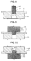
- Fig. 11 is an explanatory view showing a fourth manufacturing step when the belt mounting clamp is manufactured.
- S designates the vehicle body of an automobile, D a driver's seat, and 1 a seat belt device.
- a retractor 11 for a shoulder belt is fixed to the vehicle body S.
- a shoulder belt 12 is connected to this retractor 11.
- a belt mounting clamp A1 is fixed to one side of the seat D in the vehicle body S.
- a waist belt 13 is connected to this belt mounting clamp A1.
- the connecting parts of the one and the other long edge parts 691 and 692 namely, the short edge parts 7 and 7 are shaped in smooth circular arc in configuration, even when both the end parts of the waist belt 13 along its longitudinal direction are expanded in a circular arc shape, the expanded parts do not collide with the short edge parts 7 and 7. Therefore, the waist belt 13 can be advantageously readily inserted into the slot 6. In addition, both the end parts of the waist belt 13 can fit in the short edge parts 7 and 7. When tension acts on the waist belt 13, the belt 13 can be stably held in its prescribed position of the slot 6.
- the steel plate S which forms a belt mounting clamp is bent substantially at right angles with the rest of the steel plate S along a bent part 2a by employing a metal mold K31 and a metal mold K32.
- a belt mounting clamp A1 as shown in Fig. 22 is completed.
- the protrusions protrude on both the one surface 22a side and the other surface 22b side of the base 2, the protrusion may only protrude either on one surface 22a or on the other surface 22b.
- a method for forming the protrusion protruding only on one side may be achieved by carrying out fifth to seventh steps shown in Figs. 23 to 25 after the fourth step shown in Fig. 11.
- the other long edge part 692 has been curved in configuration in a similar way to the one long edge part 691, the other long edge part 692 may be formed in a linear shape or other shape. In this case, the other long edge part 692 is preferably formed to be curved substantially similarly to the one long edge part 691 so that the belt can be easily inserted into the slot.
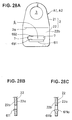
- the slot 6 is formed in an elongated shape, as shown in Fig. 28A.
- a protrusion 611 is formed only on one long edge part 691. This protrusion 611 protrudes only on the other surface 22b side of a base 2, as illustrated in Fig. 28B.
- the protrusion 611 may be formed as one protrusion 611a and the other protrusion 611b to protrude respectively from one surface 22a side and the other surface 22b from the base 2, as shown in Fig. 28C.
- a sixth embodiment of the present invention will be described in the following.
- common components to those of the fourth embodiment are affixed with the same reference symbols and the explanation thereof will be simplified.
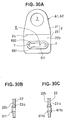
- the sixth embodiment is different from the fourth embodiment in that a protrusion 611 is formed on one long edge part 691, the other long edge part 692 and two short edge parts 7 and 7.
- the entire part of the slot 6 can be strengthened due to the presence of the protrusion 611 or the one protrusion 611a and the other protrusion 611b.
- operational effects similar to those of the fourth embodiment and the fifth embodiment can be attained.
- the protrusion 611 can be clearly projected in the burring step P3, and the corner parts of the protrusion 611 are clearly formed in a curved surface shape in the curved-surface forming step P4. Further, the edge part 6a opposite to the protrusion 611 in the slot 6 can be smoothly rounded with larger radius of curvature owing to the restriking step P5. Accordingly, since the corner parts in the slot 6 can be finished to be rounded only by the press machine, a finish working (barrel finish working) or a coating work does not need to be done in another step. Therefore, cost can be reduced.
- the protrusion 611 is formed by projecting a part of the steel plate S based on the burring work, it can be largely projected from the base 2.
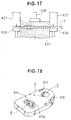
- the protrusion 611 can be formed so that the amount of protrusion H of this protrusion 611 ranges from 15% to 60% as thick as the thickness T of the base 2, as can be seen in Fig. 32. Therefore, while the contact area of the belt with the belt mounting clamp can be increased, surface pressure exerted upon the belt can be decreased.
- the amount of protrusion H is preferably located within a range of 20% to 50% of the thickness T of the base.
- the width of the belt is properly maintained in the one long edge part, the tension of the belt is evenly transmitted to the one long edge part. Consequently, the durability of the belt and the belt mounting clamp can be improved and safety can be improved owing to the improvement of their durability.
- the configuration of the one or the other long edge part substantially correspond to that of the belt curved as stated above.
- the belt can be more easily inserted into the slot than in the case mentioned above.
- short edge parts through which the one long edge part is connected to the other long edge part are formed in curved shapes of circular arc which are smoothly continued from one and the other long edge parts, the rounded and expanded parts at both the ends of the belt hardly collide with the short edge parts.
- the belt can be advantageously more readily inserted into the slot.
- the one long edge part since the one long edge part has a protrusion which protrudes from one surface side of the plate shaped member, the contact surface area of the belt abutting against the one long edge part is increased. As a result, the surface pressure of the belt can be reduced. Further, since the corner parts of the one long edge part are rounded along the direction in which the belt is folded back, the belt is prevented from breaking in the corner parts. Furthermore, since the corner parts are rounded and these corner parts do not need to undergo a coating work with vinyl chloride or polyethylene or the like, cost required for such a coating work can be reduced. That is, the cost can be lowered.
- a protrusion which protrudes from the other surface of the plate shaped member is formed by bending a part of the plate shaped member from the one surface side to the other surface side of the plate shaped member, the protrusion can be projected greatly from the other surface side. Therefore, the area of the belt abutting against the one long edge part can be increased. In other words, surface pressure exerted on the belt from the one long edge part can be completely lowered. Therefore, the durability of the belt and the strength of the belt mounting clamp can be improved, and safety can be improved based on the improvement of their durability and strength. Further, since the corner parts of the one long edge part are rounded, the belt can be prevented from being broken in these corner parts. Additionally, since the corner parts are rounded and do not need to be subjected to a coating work with vinyl chloride or polyethylene or the like, cost necessary for such a coating work can be reduced. Namely, the cost can be lowered.
- the short edge parts are also provided with a protrusion, so that the strength of the short edge parts can be increased. Therefore, even if the belt is gathered to the short edge part so that force is concentrated to the short edge part, the safety of the short edge part can be more improved than the past until the present.
- the strength of an entire part around the slot can be improved.
- the contact surface area the belt which abuts against the one long edge part can be increased owing to the presence of the protrusion.
- the surface pressure of the belt can be reduced.
- the protrusions are formed so as to protrude from both the one surface side and the other surface side of the plate member, the surface pressure of the belt can be most reduced.
- the amount of protrusion of the respective protrusions which are projected from the plate shaped member ranges from 20% to 60% as thick as the thickness of the plate shaped member, so that the contact surface area of the belt which abuts against the one long edge part can be increased.
- a magnification as 20% to 60% is enabled by forming the part of the slot by a bending work as in the invention claimed in claim 5 or 7, or forming it by a burring work as in the invention claimed in claim 14 or 15.
- the protrusion can be clearly projected in a burring step and the corner parts of the protrusion can be finely formed in a curved-surface forming step.
- the edge part opposite to the protrusion in the slot can be smoothly rounded with a larger radius of curvature in a restriking step. Therefore, since the corner parts can be finished so as to be rounded in a series of press working steps for forming the belt mounting clamp, a finishing work or a coating work must not be carried out in another step. Accordingly, the cost can be reduced.
Landscapes
- Engineering & Computer Science (AREA)
- Mechanical Engineering (AREA)
- Automotive Seat Belt Assembly (AREA)
- Clamps And Clips (AREA)
Priority Applications (3)
| Application Number | Priority Date | Filing Date | Title |
|---|---|---|---|
| EP03018277A EP1361123A3 (de) | 1994-08-31 | 1995-08-29 | Sicherheitsgurt-Verankerungsplatte und Verfahren zum Herstellen derselben |
| EP00203961A EP1086864B1 (de) | 1994-08-31 | 1995-08-29 | Verfahren zum Herstellen einer Sicherheitsgurt- Verankerungsplatte |
| DK00203961T DK1086864T3 (da) | 1994-08-31 | 1995-08-29 | Fremgangsmåde ved fremstilling af bæltemonteringsbeslag til sikkerhedsbæltesamling |
Applications Claiming Priority (7)
| Application Number | Priority Date | Filing Date | Title |
|---|---|---|---|
| JP206853/94 | 1994-08-31 | ||
| JP20685394 | 1994-08-31 | ||
| JP20685394 | 1994-08-31 | ||
| JP2307695A JP3095967B2 (ja) | 1994-08-31 | 1995-02-10 | シートベルト装置用ベルト取付金具 |
| JP23076/95 | 1995-02-10 | ||
| JP2307695 | 1995-02-10 | ||
| PCT/JP1995/001709 WO1996006760A1 (en) | 1994-08-31 | 1995-08-29 | Belt fixture for seat belt assembly and process for production thereof |
Related Child Applications (4)
| Application Number | Title | Priority Date | Filing Date |
|---|---|---|---|
| EP03018277A Division EP1361123A3 (de) | 1994-08-31 | 1995-08-29 | Sicherheitsgurt-Verankerungsplatte und Verfahren zum Herstellen derselben |
| EP00203961A Division EP1086864B1 (de) | 1994-08-31 | 1995-08-29 | Verfahren zum Herstellen einer Sicherheitsgurt- Verankerungsplatte |
| EP00203961.8 Division-Into | 2000-11-10 | ||
| EP03018277.8 Division-Into | 2003-08-12 |
Publications (3)
| Publication Number | Publication Date |
|---|---|
| EP0726186A1 true EP0726186A1 (de) | 1996-08-14 |
| EP0726186A4 EP0726186A4 (de) | 2000-04-26 |
| EP0726186B1 EP0726186B1 (de) | 2003-11-26 |
Family
ID=26360378
Family Applications (3)
| Application Number | Title | Priority Date | Filing Date |
|---|---|---|---|
| EP95929244A Expired - Lifetime EP0726186B1 (de) | 1994-08-31 | 1995-08-29 | Verankerungsvorrichtung für einen sicherheitsgurt und verfahren zu ihrer herstellung |
| EP00203961A Expired - Lifetime EP1086864B1 (de) | 1994-08-31 | 1995-08-29 | Verfahren zum Herstellen einer Sicherheitsgurt- Verankerungsplatte |
| EP03018277A Withdrawn EP1361123A3 (de) | 1994-08-31 | 1995-08-29 | Sicherheitsgurt-Verankerungsplatte und Verfahren zum Herstellen derselben |
Family Applications After (2)
| Application Number | Title | Priority Date | Filing Date |
|---|---|---|---|
| EP00203961A Expired - Lifetime EP1086864B1 (de) | 1994-08-31 | 1995-08-29 | Verfahren zum Herstellen einer Sicherheitsgurt- Verankerungsplatte |
| EP03018277A Withdrawn EP1361123A3 (de) | 1994-08-31 | 1995-08-29 | Sicherheitsgurt-Verankerungsplatte und Verfahren zum Herstellen derselben |
Country Status (9)
| Country | Link |
|---|---|
| US (3) | US5899499A (de) |
| EP (3) | EP0726186B1 (de) |
| JP (1) | JP3095967B2 (de) |
| KR (1) | KR100196030B1 (de) |
| AU (1) | AU688567B2 (de) |
| DE (3) | DE19549650C2 (de) |
| DK (2) | DK0726186T3 (de) |
| GB (1) | GB2301764B (de) |
| WO (1) | WO1996006760A1 (de) |
Cited By (1)
| Publication number | Priority date | Publication date | Assignee | Title |
|---|---|---|---|---|
| WO1999007581A1 (en) * | 1997-08-07 | 1999-02-18 | Breed Automotive Technology, Inc | Webbing guide |
Families Citing this family (32)
| Publication number | Priority date | Publication date | Assignee | Title |
|---|---|---|---|---|
| DE19680170C2 (de) * | 1995-02-10 | 2001-11-15 | Enshu Co | Sicherheitsgurtaufhängungs- und halteteil |
| JP2000177534A (ja) * | 1998-12-17 | 2000-06-27 | Takata Corp | シートベルト装置用ショルダーアンカ− |
| US6279945B1 (en) * | 2000-01-07 | 2001-08-28 | Autoliv Asp, Inc. | Guide fitting for inflatable vehicular safety belt |
| JP3445241B2 (ja) * | 2000-06-30 | 2003-09-08 | 株式会社遠州 | シートベルト吊持具及びその製造方法 |
| GB2380457B (en) * | 2000-06-30 | 2003-09-17 | Enshu Co Ltd | Loop hanger for seat belt and method for manufacturing same |
| DE10034521A1 (de) * | 2000-07-15 | 2002-01-24 | Volkswagen Ag | Umlenkbeschlag für einen Sicherheitsgurt |
| US6520588B1 (en) * | 2000-11-16 | 2003-02-18 | Trw Vehicle Safety Systems Inc. | Seat belt guide |
| KR100397233B1 (ko) * | 2001-02-23 | 2003-09-13 | 델파이 오토모티브 시스템스 성우 주식회사 | 시트벨트 어셈블리용 공장자동화설비의 제어 시스템 및 방법 |
| JP2007050824A (ja) * | 2005-08-19 | 2007-03-01 | Takata Corp | シートベルト用ガイドアンカーおよびこれを備えたシートベルト装置 |
| US20070138783A1 (en) * | 2005-12-20 | 2007-06-21 | Trw Vehicle Safety Systems Inc. | Guide for seat belt webbing having a deformable insert |
| US7566075B2 (en) * | 2006-02-06 | 2009-07-28 | Toyota Motor Engineering & Manufacturing North America, Inc. | Seat belt shoulder guide |
| US7390022B2 (en) * | 2006-08-04 | 2008-06-24 | Tk Holdings Inc. | Integrated seat belt shoulder anchor |
| US20080236958A1 (en) * | 2007-03-29 | 2008-10-02 | Debiasi International Limited | Pressure vessel for vehicular air brake system |
| JP4925445B2 (ja) * | 2007-04-13 | 2012-04-25 | タカタ株式会社 | ベルトガイドアンカーおよびこれを備えたシートベルト装置 |
| JP4527138B2 (ja) | 2007-07-12 | 2010-08-18 | 本田技研工業株式会社 | ハイブリッド車両の制御装置 |
| DE102007034765B3 (de) * | 2007-07-25 | 2008-10-16 | Autoliv Development Ab | Profilschiene für ein höhenverstellbares Beschlagteil und Verfahren zu ihrer Herstellung |
| DE102007044155B4 (de) * | 2007-09-15 | 2022-01-13 | Autoliv Development Ab | Beschlagteil für das Sicherheitsgurtsystem eines Kraftfahrzeugs |
| WO2010081508A1 (de) | 2009-01-13 | 2010-07-22 | Keiper Gmbh & Co. Kg | Fahrzeugsitz, insbesondere kraftfahrzeugsitz |
| DE102009005130B4 (de) | 2009-01-13 | 2023-05-04 | Keiper Seating Mechanisms Co., Ltd. | Struktur für einen Fahrzeugsitz |
| ES2365341B1 (es) * | 2009-10-16 | 2012-09-14 | Fabricación Asientos Vehículos Industriales, S.A. | Sistema de guiado para el cinturón de seguridad que sujeta a los viajeros de un vehículo. |
| DE102009057928B4 (de) * | 2009-12-09 | 2023-01-19 | Keiper Seating Mechanisms Co., Ltd. | Fahrzeugsitz, insbesondere Kraftfahrzeugsitz |
| JP2012191081A (ja) * | 2011-03-11 | 2012-10-04 | Funai Electric Co Ltd | 壁掛け金具取付け部材の装着部構造 |
| JP2012191082A (ja) * | 2011-03-11 | 2012-10-04 | Funai Electric Co Ltd | 壁掛け金具取付け部材の装着部構造 |
| JP2014189039A (ja) * | 2013-03-26 | 2014-10-06 | Autoliv Development Ab | カーテンエアバッグ取付用ブラケットおよびカーテンエアバッグ |
| DE102013106720B4 (de) * | 2013-06-26 | 2017-11-09 | Grammer Ag | Fahrzeugsitz |
| DE102013014707A1 (de) * | 2013-09-05 | 2015-03-05 | GM Global Technology Operations LLC (n. d. Ges. d. Staates Delaware) | Anordnung eines Umlenkbeschlags für einen Sicherheitsgurt an einer Fahrzeugstruktur |
| KR20190067278A (ko) * | 2014-01-27 | 2019-06-14 | 가부시키가이샤 엔슈 | 벨트 부착구 |
| US9358914B2 (en) * | 2014-06-05 | 2016-06-07 | Amsafe, Inc. | Seatbelt anchor systems for aircraft and other vehicles, and associated methods of manufacture and use |
| US20160311396A1 (en) * | 2015-04-24 | 2016-10-27 | GM Global Technology Operations LLC | Belt buckle anchor for thin seats |
| US10897964B1 (en) | 2019-07-02 | 2021-01-26 | Intertek Industrial Corporation | Adjustable connectors for use with webbing of patient harness systems and other types of safety belt systems |
| US11246379B2 (en) | 2019-07-02 | 2022-02-15 | Intertek Industrial Corporation | Adjustable connectors for use with webbing of patient harness systems and other types of safety belt systems |
| US20240247682A1 (en) * | 2023-01-20 | 2024-07-25 | Honda Motor Co., Ltd. | Mounting assembly for transportation and/or handling of a vehicle part |
Family Cites Families (31)
| Publication number | Priority date | Publication date | Assignee | Title |
|---|---|---|---|---|
| US488135A (en) * | 1892-12-13 | Chusetts | ||
| BE561328A (de) * | ||||
| US2460721A (en) * | 1945-07-07 | 1949-02-01 | Inland Steel Co | Method of forming bungs in metallic plates |
| US3428362A (en) * | 1967-10-16 | 1969-02-18 | Ford Motor Co | Seat belt utilization indicator |
| US3575122A (en) * | 1968-07-03 | 1971-04-13 | Stanray Corp | Methods of constructing a hatch frame and cover therefor |
| JPS5126610U (de) * | 1974-08-17 | 1976-02-26 | ||
| NO139078C (no) * | 1975-05-20 | 1979-01-10 | Loyd S Industri As | Omlenkingsbeslag for beltebaand saasom bilbelte eller lignende |
| US4103933A (en) * | 1976-01-12 | 1978-08-01 | Robert C. Fisher | Floor anchor for seat belt |
| SU683840A1 (ru) * | 1977-11-09 | 1979-09-05 | Ростовский-На-Дону Завод-Втуз При Заводе Ростсельмаш | Штамп совмещенного действи дл обработки листового материала |
| US4150556A (en) * | 1978-02-27 | 1979-04-24 | Mccord Corporation | Radiator tank headsheet and method |
| DE3116910A1 (de) * | 1981-04-29 | 1982-11-18 | August 3538 Marsberg Weber | Befestigungshalter zur schraublosen befestigung von sicherheitsgurten und mit oder ohne stossmindernder bremseinrichtung |
| SU1034814A1 (ru) * | 1981-05-26 | 1983-08-15 | Всесоюзный научно-исследовательский институт по строительству магистральных трубопроводов | Способ получени горловин |
| DE3144527A1 (de) * | 1981-11-10 | 1983-05-19 | Klippan GmbH, Sicherheitsgeräte, 2000 Norderstedt | Vorrichtung zur fuehrung oder umlenkung eines bandes, insbesondere fuer einen sicherheitsgurt in einem kraftfahrzeug |
| DE3144927A1 (de) * | 1981-11-12 | 1983-05-19 | Bengel, Friedrich, 7148 Remseck | Flurfoerdergeraet |
| DE3306095A1 (de) * | 1983-02-22 | 1984-08-30 | Repa Feinstanzwerk Gmbh, 7071 Alfdorf | Umlenkbeschlag fuer sicherheitsgurte in kraftfahrzeugen |
| GB8308274D0 (en) * | 1983-03-25 | 1983-05-05 | Britax Kolb Gmbh & Co | Safety belt guide member |
| JPS60213321A (ja) * | 1984-04-10 | 1985-10-25 | Nissan Motor Co Ltd | プレス型 |
| JPS61171655U (de) * | 1985-04-15 | 1986-10-24 | ||
| EP0223582A3 (de) * | 1985-11-22 | 1988-02-10 | Britax (Wingard) Limited | Schulterumlenkbeschlag für einen Sicherheitsgurt |
| JPH02120272A (ja) * | 1988-10-28 | 1990-05-08 | Kawasaki Refract Co Ltd | 黒鉛含有MgO−CaO質耐火物 |
| JPH02147128A (ja) * | 1988-11-26 | 1990-06-06 | Mitsumi Electric Co Ltd | プレス加工に於ける軸受加工法 |
| JPH0735801Y2 (ja) * | 1989-03-15 | 1995-08-16 | 富士オートリブ株式会社 | 安全ベルトのウエビング連結用金具 |
| DE3924149A1 (de) * | 1989-07-21 | 1991-01-31 | Porsche Ag | Sicherheitsgurtsystem, insbesondere fuer kraftfahrzeuge |
| FR2666527B1 (fr) * | 1990-09-10 | 1995-01-27 | Goro Sa | Procede de fabrication de dispositifs de jonction pour tapis transporteurs ou similaires, et dispositifs de jonction ainsi fabriques. |
| DE9102217U1 (de) * | 1991-02-25 | 1991-07-04 | Autoliv Development AB, Vårgårda | Rückhaltesystem |
| DE4211471C2 (de) * | 1991-04-12 | 1996-08-29 | Keiper Recaro Gmbh Co | Fahrzeugsitz, insbesondere Kraftfahrzeugsitz |
| US5207452A (en) * | 1992-02-13 | 1993-05-04 | General Safety Corporation | Removable seat belt guide ring |
| US5237849A (en) * | 1992-02-19 | 1993-08-24 | Hidaka Seiki Kabushiki Kaisha | Method of manufacturing fins for heat exchangers |
| DE69509073T2 (de) * | 1994-02-17 | 1999-11-11 | Breed Automotive Technology, Inc. | Umlenkung für einen sicherheitsgurt |
| JP3247548B2 (ja) * | 1994-06-14 | 2002-01-15 | タカタ株式会社 | シートベルト装置用スリップアンカー |
| DE69617276T2 (de) * | 1995-01-11 | 2002-05-23 | Yugengaisha Mutsumichi Kenkyujo, Hamamatsu | Sicherheitsgurt-Verbindungsbeschlag und Verfahren zur Herstellung desselben |
-
1995
- 1995-02-10 JP JP2307695A patent/JP3095967B2/ja not_active Expired - Fee Related
- 1995-08-29 GB GB9608764A patent/GB2301764B/en not_active Expired - Fee Related
- 1995-08-29 DE DE1995149650 patent/DE19549650C2/de not_active Expired - Fee Related
- 1995-08-29 EP EP95929244A patent/EP0726186B1/de not_active Expired - Lifetime
- 1995-08-29 KR KR1019960702001A patent/KR100196030B1/ko not_active Expired - Lifetime
- 1995-08-29 DE DE19581199T patent/DE19581199C2/de not_active Expired - Lifetime
- 1995-08-29 DK DK95929244T patent/DK0726186T3/da active
- 1995-08-29 DE DE1995149660 patent/DE19549660C2/de not_active Expired - Fee Related
- 1995-08-29 DK DK00203961T patent/DK1086864T3/da active
- 1995-08-29 EP EP00203961A patent/EP1086864B1/de not_active Expired - Lifetime
- 1995-08-29 EP EP03018277A patent/EP1361123A3/de not_active Withdrawn
- 1995-08-29 WO PCT/JP1995/001709 patent/WO1996006760A1/ja not_active Ceased
- 1995-08-29 AU AU32659/95A patent/AU688567B2/en not_active Ceased
- 1995-08-29 US US08/635,884 patent/US5899499A/en not_active Expired - Lifetime
-
1998
- 1998-10-14 US US09/174,402 patent/US6120061A/en not_active Expired - Lifetime
-
2000
- 2000-05-22 US US09/576,583 patent/US6378350B1/en not_active Expired - Lifetime
Cited By (1)
| Publication number | Priority date | Publication date | Assignee | Title |
|---|---|---|---|---|
| WO1999007581A1 (en) * | 1997-08-07 | 1999-02-18 | Breed Automotive Technology, Inc | Webbing guide |
Also Published As
| Publication number | Publication date |
|---|---|
| DE19581199C2 (de) | 2001-03-15 |
| EP1086864A3 (de) | 2001-05-23 |
| WO1996006760A1 (en) | 1996-03-07 |
| EP0726186B1 (de) | 2003-11-26 |
| GB9608764D0 (en) | 1996-07-03 |
| DK1086864T3 (da) | 2004-08-16 |
| EP1361123A2 (de) | 2003-11-12 |
| DE19581199T1 (de) | 1996-11-14 |
| EP1086864A2 (de) | 2001-03-28 |
| DE19549650C2 (de) | 2003-02-13 |
| GB2301764A (en) | 1996-12-18 |
| US5899499A (en) | 1999-05-04 |
| US6120061A (en) | 2000-09-19 |
| EP0726186A4 (de) | 2000-04-26 |
| AU3265995A (en) | 1996-03-22 |
| DK0726186T3 (da) | 2004-03-29 |
| EP1086864B1 (de) | 2004-05-19 |
| AU688567B2 (en) | 1998-03-12 |
| KR100196030B1 (ko) | 1999-06-15 |
| EP1361123A3 (de) | 2005-11-16 |
| JP3095967B2 (ja) | 2000-10-10 |
| JPH08198053A (ja) | 1996-08-06 |
| DE19549660C2 (de) | 2003-02-13 |
| US6378350B1 (en) | 2002-04-30 |
| KR960705704A (ko) | 1996-11-08 |
| GB2301764B (en) | 1999-03-10 |
Similar Documents
| Publication | Publication Date | Title |
|---|---|---|
| EP0726186B1 (de) | Verankerungsvorrichtung für einen sicherheitsgurt und verfahren zu ihrer herstellung | |
| US5435049A (en) | Apparatus for joining sheet material | |
| EP0760316A1 (de) | Sicherheitsgurt-umlenkbeschlag | |
| EP0721867A1 (de) | Sicherheitsgurt-Verbindungsbeschlag und Verfahren zur Herstellung desselben | |
| JP3281226B2 (ja) | シートベルト装置用ベルト取付金具 | |
| US4625369A (en) | Belt fastener with enlarged loop for hinge pin | |
| US20040036344A1 (en) | Loop hanger for seat belt and method for manufacturing same | |
| US4118995A (en) | Integral tie strap and rivet assemblies for saw chains | |
| US4419800A (en) | Method of forming a cage for frusto-conical roller bearings | |
| US20050017498A1 (en) | Pillar anchor and method for manufacturing the same | |
| JP2644456B2 (ja) | ベルト連結用金具およびその製造方法 | |
| JP3382903B2 (ja) | シートベルト装置用ベルト取付金具の製造方法 | |
| US4719788A (en) | Belt fastener with enlarged loop for hinge pin | |
| JP3138624B2 (ja) | ベルト連結用金具の製造方法 | |
| KR100397383B1 (ko) | 미니 앵커 제조 방법 | |
| KR200229697Y1 (ko) | 텅 | |
| JP3281308B2 (ja) | シートベルト装置用ベルト取付金具の製造方法 | |
| KR100397485B1 (ko) | 미니 앵커 및 그 제조 방법 | |
| KR200222675Y1 (ko) | 버클베이스 | |
| JPH08301068A (ja) | シートベルト吊持具 | |
| US4191123A (en) | Method of shaping a screw type clamping collar | |
| KR200247532Y1 (ko) | 미니 앵커 | |
| JP2001138862A (ja) | ベルト連結用金具 | |
| KR200226575Y1 (ko) | 세트플레이트 | |
| JP2000142318A (ja) | シートベルト装置用ベルト取付金具及びその製造方法 |
Legal Events
| Date | Code | Title | Description |
|---|---|---|---|
| PUAI | Public reference made under article 153(3) epc to a published international application that has entered the european phase |
Free format text: ORIGINAL CODE: 0009012 |
|
| AK | Designated contracting states |
Kind code of ref document: A1 Designated state(s): DK FR NL SE |
|
| 17P | Request for examination filed |
Effective date: 19960903 |
|
| A4 | Supplementary search report drawn up and despatched |
Effective date: 20000310 |
|
| AK | Designated contracting states |
Kind code of ref document: A4 Designated state(s): DK FR NL SE |
|
| 17Q | First examination report despatched |
Effective date: 20001122 |
|
| RTI1 | Title (correction) |
Free format text: BELT MOUNTING CLAMP FOR SEAT BELT ASSEMBLY AND PROCESS FOR PRODUCTION THEREOF |
|
| GRAH | Despatch of communication of intention to grant a patent |
Free format text: ORIGINAL CODE: EPIDOS IGRA |
|
| GRAS | Grant fee paid |
Free format text: ORIGINAL CODE: EPIDOSNIGR3 |
|
| GRAA | (expected) grant |
Free format text: ORIGINAL CODE: 0009210 |
|
| AK | Designated contracting states |
Kind code of ref document: B1 Designated state(s): DK FR NL SE |
|
| REG | Reference to a national code |
Ref country code: SE Ref legal event code: TRGR |
|
| REG | Reference to a national code |
Ref country code: DK Ref legal event code: T3 |
|
| ET | Fr: translation filed | ||
| PLBE | No opposition filed within time limit |
Free format text: ORIGINAL CODE: 0009261 |
|
| STAA | Information on the status of an ep patent application or granted ep patent |
Free format text: STATUS: NO OPPOSITION FILED WITHIN TIME LIMIT |
|
| 26N | No opposition filed |
Effective date: 20040827 |
|
| PGFP | Annual fee paid to national office [announced via postgrant information from national office to epo] |
Ref country code: DK Payment date: 20070719 Year of fee payment: 13 |
|
| PGFP | Annual fee paid to national office [announced via postgrant information from national office to epo] |
Ref country code: NL Payment date: 20070719 Year of fee payment: 13 |
|
| REG | Reference to a national code |
Ref country code: DK Ref legal event code: EBP |
|
| NLV4 | Nl: lapsed or anulled due to non-payment of the annual fee |
Effective date: 20090301 |
|
| PG25 | Lapsed in a contracting state [announced via postgrant information from national office to epo] |
Ref country code: NL Free format text: LAPSE BECAUSE OF NON-PAYMENT OF DUE FEES Effective date: 20090301 |
|
| PG25 | Lapsed in a contracting state [announced via postgrant information from national office to epo] |
Ref country code: DK Free format text: LAPSE BECAUSE OF NON-PAYMENT OF DUE FEES Effective date: 20080831 |
|
| PGFP | Annual fee paid to national office [announced via postgrant information from national office to epo] |
Ref country code: FR Payment date: 20120709 Year of fee payment: 18 |
|
| PGFP | Annual fee paid to national office [announced via postgrant information from national office to epo] |
Ref country code: SE Payment date: 20120822 Year of fee payment: 18 |
|
| REG | Reference to a national code |
Ref country code: SE Ref legal event code: EUG |
|
| PG25 | Lapsed in a contracting state [announced via postgrant information from national office to epo] |
Ref country code: SE Free format text: LAPSE BECAUSE OF NON-PAYMENT OF DUE FEES Effective date: 20130830 |
|
| REG | Reference to a national code |
Ref country code: FR Ref legal event code: ST Effective date: 20140430 |
|
| PG25 | Lapsed in a contracting state [announced via postgrant information from national office to epo] |
Ref country code: FR Free format text: LAPSE BECAUSE OF NON-PAYMENT OF DUE FEES Effective date: 20130902 |