EP0727103B1 - Vorrichtung zum verdrahten eines verbinders - Google Patents
Vorrichtung zum verdrahten eines verbinders Download PDFInfo
- Publication number
- EP0727103B1 EP0727103B1 EP94931029A EP94931029A EP0727103B1 EP 0727103 B1 EP0727103 B1 EP 0727103B1 EP 94931029 A EP94931029 A EP 94931029A EP 94931029 A EP94931029 A EP 94931029A EP 0727103 B1 EP0727103 B1 EP 0727103B1
- Authority
- EP
- European Patent Office
- Prior art keywords
- wire
- selection
- processing unit
- wires
- slot
- Prior art date
- Legal status (The legal status is an assumption and is not a legal conclusion. Google has not performed a legal analysis and makes no representation as to the accuracy of the status listed.)
- Expired - Lifetime
Links
- 238000003780 insertion Methods 0.000 claims description 17
- 230000037431 insertion Effects 0.000 claims description 17
- 238000000034 method Methods 0.000 claims description 7
- 238000010586 diagram Methods 0.000 description 8
- 239000003086 colorant Substances 0.000 description 1
- 230000005484 gravity Effects 0.000 description 1
- 238000009413 insulation Methods 0.000 description 1
Images

Classifications
-
- H—ELECTRICITY
- H01—ELECTRIC ELEMENTS
- H01R—ELECTRICALLY-CONDUCTIVE CONNECTIONS; STRUCTURAL ASSOCIATIONS OF A PLURALITY OF MUTUALLY-INSULATED ELECTRICAL CONNECTING ELEMENTS; COUPLING DEVICES; CURRENT COLLECTORS
- H01R43/00—Apparatus or processes specially adapted for manufacturing, assembling, maintaining, or repairing of line connectors or current collectors or for joining electric conductors
- H01R43/01—Apparatus or processes specially adapted for manufacturing, assembling, maintaining, or repairing of line connectors or current collectors or for joining electric conductors for connecting unstripped conductors to contact members having insulation cutting edges
-
- G—PHYSICS
- G01—MEASURING; TESTING
- G01R—MEASURING ELECTRIC VARIABLES; MEASURING MAGNETIC VARIABLES
- G01R31/00—Arrangements for testing electric properties; Arrangements for locating electric faults; Arrangements for electrical testing characterised by what is being tested not provided for elsewhere
- G01R31/50—Testing of electric apparatus, lines, cables or components for short-circuits, continuity, leakage current or incorrect line connections
- G01R31/58—Testing of lines, cables or conductors
- G01R31/60—Identification of wires in a multicore cable
-
- H—ELECTRICITY
- H01—ELECTRIC ELEMENTS
- H01R—ELECTRICALLY-CONDUCTIVE CONNECTIONS; STRUCTURAL ASSOCIATIONS OF A PLURALITY OF MUTUALLY-INSULATED ELECTRICAL CONNECTING ELEMENTS; COUPLING DEVICES; CURRENT COLLECTORS
- H01R43/00—Apparatus or processes specially adapted for manufacturing, assembling, maintaining, or repairing of line connectors or current collectors or for joining electric conductors
- H01R43/28—Apparatus or processes specially adapted for manufacturing, assembling, maintaining, or repairing of line connectors or current collectors or for joining electric conductors for wire processing before connecting to contact members, not provided for in groups H01R43/02 - H01R43/26
-
- G—PHYSICS
- G01—MEASURING; TESTING
- G01J—MEASUREMENT OF INTENSITY, VELOCITY, SPECTRAL CONTENT, POLARISATION, PHASE OR PULSE CHARACTERISTICS OF INFRARED, VISIBLE OR ULTRAVIOLET LIGHT; COLORIMETRY; RADIATION PYROMETRY
- G01J3/00—Spectrometry; Spectrophotometry; Monochromators; Measuring colours
- G01J3/46—Measurement of colour; Colour measuring devices, e.g. colorimeters
- G01J2003/466—Coded colour; Recognition of predetermined colour; Determining proximity to predetermined colour
-
- Y—GENERAL TAGGING OF NEW TECHNOLOGICAL DEVELOPMENTS; GENERAL TAGGING OF CROSS-SECTIONAL TECHNOLOGIES SPANNING OVER SEVERAL SECTIONS OF THE IPC; TECHNICAL SUBJECTS COVERED BY FORMER USPC CROSS-REFERENCE ART COLLECTIONS [XRACs] AND DIGESTS
- Y10—TECHNICAL SUBJECTS COVERED BY FORMER USPC
- Y10T—TECHNICAL SUBJECTS COVERED BY FORMER US CLASSIFICATION
- Y10T29/00—Metal working
- Y10T29/51—Plural diverse manufacturing apparatus including means for metal shaping or assembling
- Y10T29/5193—Electrical connector or terminal
-
- Y—GENERAL TAGGING OF NEW TECHNOLOGICAL DEVELOPMENTS; GENERAL TAGGING OF CROSS-SECTIONAL TECHNOLOGIES SPANNING OVER SEVERAL SECTIONS OF THE IPC; TECHNICAL SUBJECTS COVERED BY FORMER USPC CROSS-REFERENCE ART COLLECTIONS [XRACs] AND DIGESTS
- Y10—TECHNICAL SUBJECTS COVERED BY FORMER USPC
- Y10T—TECHNICAL SUBJECTS COVERED BY FORMER US CLASSIFICATION
- Y10T29/00—Metal working
- Y10T29/53—Means to assemble or disassemble
- Y10T29/53087—Means to assemble or disassemble with signal, scale, illuminator, or optical viewer
- Y10T29/53091—Means to assemble or disassemble with signal, scale, illuminator, or optical viewer for work-holder for assembly or disassembly
-
- Y—GENERAL TAGGING OF NEW TECHNOLOGICAL DEVELOPMENTS; GENERAL TAGGING OF CROSS-SECTIONAL TECHNOLOGIES SPANNING OVER SEVERAL SECTIONS OF THE IPC; TECHNICAL SUBJECTS COVERED BY FORMER USPC CROSS-REFERENCE ART COLLECTIONS [XRACs] AND DIGESTS
- Y10—TECHNICAL SUBJECTS COVERED BY FORMER USPC
- Y10T—TECHNICAL SUBJECTS COVERED BY FORMER US CLASSIFICATION
- Y10T29/00—Metal working
- Y10T29/53—Means to assemble or disassemble
- Y10T29/5313—Means to assemble electrical device
- Y10T29/532—Conductor
- Y10T29/53209—Terminal or connector
- Y10T29/53213—Assembled to wire-type conductor
-
- Y—GENERAL TAGGING OF NEW TECHNOLOGICAL DEVELOPMENTS; GENERAL TAGGING OF CROSS-SECTIONAL TECHNOLOGIES SPANNING OVER SEVERAL SECTIONS OF THE IPC; TECHNICAL SUBJECTS COVERED BY FORMER USPC CROSS-REFERENCE ART COLLECTIONS [XRACs] AND DIGESTS
- Y10—TECHNICAL SUBJECTS COVERED BY FORMER USPC
- Y10T—TECHNICAL SUBJECTS COVERED BY FORMER US CLASSIFICATION
- Y10T29/00—Metal working
- Y10T29/53—Means to assemble or disassemble
- Y10T29/5313—Means to assemble electrical device
- Y10T29/532—Conductor
- Y10T29/53243—Multiple, independent conductors
-
- Y—GENERAL TAGGING OF NEW TECHNOLOGICAL DEVELOPMENTS; GENERAL TAGGING OF CROSS-SECTIONAL TECHNOLOGIES SPANNING OVER SEVERAL SECTIONS OF THE IPC; TECHNICAL SUBJECTS COVERED BY FORMER USPC CROSS-REFERENCE ART COLLECTIONS [XRACs] AND DIGESTS
- Y10—TECHNICAL SUBJECTS COVERED BY FORMER USPC
- Y10T—TECHNICAL SUBJECTS COVERED BY FORMER US CLASSIFICATION
- Y10T29/00—Metal working
- Y10T29/53—Means to assemble or disassemble
- Y10T29/5313—Means to assemble electrical device
- Y10T29/53265—Means to assemble electrical device with work-holder for assembly
Definitions
- the invention relates to an apparatus for wiring a connector according to the preamble of claim 1.
- An apparatus of the above-mentioned type is for example disclosed in EP-A-0 390 080.
- the known apparatus For identifying a wire of a number of wires, for example, combined in a cable, the known apparatus requires that on the one hand each wire of the bundle must be connected to a connecting unit in a predetermined manner and a second physical electric contact must be made with each wire. Thereby, the known apparatus is rather complicated and the use of the apparatus is cumbersome.
- the invention aims to provide an apparatus of the above-mentioned type which is made in a relatively simple manner and by means of which a connector can be wired with high speed.
- the apparatus is characterized by a colour camera for observing a separated wire, wherein the processing unit determines the colour code of the observed wire from the picture signal of the colour camera and retrieves the position of the corresponding contact in the connector to be wired from a table, whereafter the processing unit controls the shutter of the wire selection means for delivering the wire, controls the gripper moving means for feeding the delivered wire to the corresponding wire guiding means and controls the tool moving means for aligning the tool with the corresponding contact.
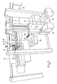
- Fig. 1 shows schematically a perspective view of the main part of an embodiment of the apparatus according to the invention.
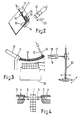
- Fig. 2 shows a very schematical perspective view of some important components of the apparatus of Fig. 1.
- Fig. 3 shows very schematically a side view of the apparatus of Fig. 1.
- Fig. 4 shows very schematically a top view of a part of the apparatus of Fig. 1.
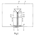
- Fig. 5 is a block diagram of the apparatus of Fig. 1.
- Fig. 6 is a front view of an alternative embodiment of the wire selection means for use in the apparatus of Fig. 1.
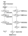
- Fig. 7 shows a flow diagram for the explanation of the method used in the apparatus of Fig. 1.
- Figs. 1-5 schematically show an apparatus for wiring a connector 1 having a plurality of contacts 2 of the IDC-type.
- Fig. 1 partially shows a perspective view of the main part of the apparatus and
- Fig. 2-4 very schematically shows different views to further explain the basic elements of this apparatus.
- the apparatus comprises a holder 3 in which the connector 1 to be wired is placed, wherein a wire insertion head 4 is located at each side of the holder 3, said wire insertion head having a tool 5 movable back and forth transverse to the longitudinal direction of the holder 3.
- Each wire insertion head 4 further comprises a wire guiding means 6 into which a wire to be connected to a contact 2, can be brought.
- the wire insertion heads 4 are movable in the longitudinal direction of the holder 3 by a driving means 7 indicated in the block diagram of Fig. 5, so that the tools 5 can be aligned with each contact 2 of the connector 1 located in the holder 3.
- the apparatus further comprises wire selection means which are mounted in a predetermined fixed position.
- the wires are generally part of a cable 8 which is clamped in a cable clamp 9 schematically shown.
- the wires 10 are inserted into an insertion opening 11 of a stationary located wire selection plate 12 which is part of the wire selection means.
- a selection slot 13 is provided in the wire selection plate 12, said slot 13 joining the insertion opening 11 at one side and at the other side debouching with an outlet in an edge of the wire selection plate 12 lying below the insertion opening 11.
- the wires 10 inserted into the insertion opening 11 fall in a random order into the selection slot 13, the width of which corresponds with the diameter of the individual wires 10.
- the outlet of the selection slot 13 is closed by a shutter 14 which is operable in a manner not further shown for opening the outlet of the wire selection slot 13.
- the wire selection means comprises a slide 15 with a wedge-shaped end, said slide being movable transverse to the selection slot 13 in a manner also not further shown.
- the wires 10 which fall into the selection slot 13 under influence of the gravity, are pressed downwards by a pressing member 16.
- the apparatus is further provided with a gripper 17 with a fixed upper jaw part 18 and a movable lower jaw part 19.
- the gripper 17 is movable in the x-, y- and z-directions by means 20 schematically shown in Fig. 3.
- the gripper moving means 20 includes three motors 27, 28 and 29 shown in Fig. 1. By means of the motor 27 the gripper 17 can be moved towards the connector 1 and back. By means of the motor 28 and 29 the gripper can be moved to the left and right and up and down, respectively.
- the apparatus comprises a processing unit 21 schematically indicated in Fig. 5, said processing unit 21 being provided with high speed microprocessors.
- a colour camera 22 is connected to the processing unit 21, which camera 22 provides colour signals by means of which the processing unit can identify an observed wire.
- a light source 23 illuminates the wire adjacent the shutter 14, so that the colour camera 22 can observe a constantly illuminated picture.
- Wiring diagrams for various connectors can be stored in a memory 24, wherein, through a keyboard 25, the processing unit 21 can be set for wiring a certain connector and the processing unit will control the wiring process by means of the wiring diagram stored in the memory 24.
- the processing unit 21 actuates the slide 15 operating as a separator so that the wire 10 adjacent the shutter 14 will be separated from the remaining wires 10.
- the separated wire 10 is illuminated by the light source 23 and the colour camera 22 supplies picture signals to the processing unit 21.
- the processing unit 21 controls the gripper moving means 20, i.e. the motors 26, 27 and 28, and the movable jaw part 19 of the gripper 17 in such a manner that the separated wire is gripped and is held in a predetermined position, so that an unambiguous observation of each separated wire is possible.
- the processing unit 21 determines the colour code of the observed wire 10 from the received picture signals of the colour camera 22.
- this colour code consists of a main colour wherein a second colour can be present or not in rings with a predetermined repetition frequency. It will be assumed hereinafter that this second colour is black. However, other colours are possible as second colour.
- the processing unit 21 determines the colour code of the separated wire 10
- the shutter 14 is opened, so that the separated wire is released.
- the remaining wires are held in the selection slot 13 by the slide 15.
- the processing unit 21 controls the gripper moving means 20 in such a manner that the gripper 17 moves the wire 10 towards the wire guiding means 6 lying at the side where the contact 2 to be wired of the connector 1 is located.
- the processing unit 21 controls the driving means 7 of the wire insertion heads 4 in such a manner that the tools 5 are aligned with the contact 2 to be wired.
- the gripper 17 moves according to a spherical shell path, the centre of which is located substantially in the cable clamp 9.
- the gripper 17 moves according to a second spherical shell path with smaller radius and tightens the wire 10 in the wire guiding means 6. Thereafter, the processing unit 21 actuates the respective tool 5 and the wire 10 is cut in a usual manner at the correct length and is attached to the respective contact 2. The cut-off wire part is disposed in a scrap container 26 by the gripper 17.
- the processing unit 21 controls the shutter 14 for closing the selection slot 13 and the slide 15 is controlled for opening the selection slot 13.
- the wires 10 move downwardly in the selection slot 13, whereafter the slide 15 separates the remaining wires 10 again from the wire 10 adjacent the shutter 14.
- a next wire can be identified and can be attached to the corresponding contact.
- the processing unit 21 stores the already connected wires 10 of a connector 1 to be wired in the memory 24. During the wiring process the processing unit 21 can thereby compare each next separated wire 10 with the wires already connected to contacts 2. If a wire is identified which according to the information stored in the memory 24, is already connected to a contact 2, the processing unit makes a new identification at another location of the wire. When the processing unit 21 finds a colour code during a renewed identification which is contrary to the first identification, for example blue instead of red, the processing unit 21 provides an alarm signal and stops the wiring process of the connector 1. If after a predetermined plurality of identification attempts, for example five, no colour code of a wire 10 not yet connected is found, an alarm signal is also provided and the wiring process of the connector 1 is stopped.
- the processing unit 21 shows the selected wiring diagram on a display 27, wherein during wiring also the progress of the wiring process and the obtained result can be shown.
- Fig. 6 shows a front view of an alternative embodiment of the wire selection means to be used in the apparatus of Fig. 1.
- the wire selection means are indicated in Fig. 6 by reference numeral 40 and comprises in the same manner as the wire selection means already described, a stationary wire selection plate 12 with an insertion opening 11 into which the wires 10 of the cable 8 can be put.
- the wires 10 are already located in the selection slot 13 which on one side joins the insertion opening 11 and on the other side debouches with an outlet in an edge 41 of the wire selection plate 12.
- a pressing means 6 presses the wires 10 into the direction of the outlet of the selection slot 13.
- the outlet of the selection slot 13 is closed by a shutter 14 which is movable back and forth as indicated by a double arrow. Therefore, the shutter 14 can open and close the outlet of the selection slot 13.
- a clamping jaw 42 or 43 is provided, said clamping jaws 42, 43 together forming a first clamping means.
- the clamping jaws 42, 43 are movable back and forth transverse to the selection slot 13 and in the longitudinal direction of the selection slot 13, as is also indicated by double arrows. Further, a clamping means 44, 45 is provided having a clamping jaw 44 or 45, respectively, at each side of the selection slot 13. These clamping jaws 44, 45 are movable back and forth transverse to the selection slot 13 only and can clamp the wire 46 adjacent the shutter 14.
- the wire selection means 40 operates as follows.
- the clamping jaws 42, 43, 44 and 45 are in the open position, so that the wires 10 fall into the selection slot 13 in a random order. Subsequently, the pressing member 6 is placed upon the upper wire 10. Thereafter, all clamping jaws 42, 43 and 44, 45 are closed, so that both the wire 46 adjacent the shutter 14 and the remaining wires 10 are clamped. Then the clamping jaws 42, 43 are moved upwardly so that the wires 10 are separated from the wire 46 adjacent the shutter 14. The thus selected wire can now be gripped by the gripper 17, whereafter the shutter 14 is opened just as the clamping jaws 44, 45, so that the gripper 17 is able to move the selected wire 46 into the connection position.
- the wire selection means 40 has the advantage that a slide for separating the wires 10 is not used, whereby damage to the wire insulation is avoided. Moreover, the wire selection means 40 can also be used for selecting twisted pair wires of a bundle.
- clamping jaws 44, 45 it is also possible to use other means for gripping the wire adjacent the shutter 14. For this purpose it would be possible, for example, to use the gripper 17 of the wiring apparatus itself.
- the identification of the colour code by the processing unit 21 preferably takes place as follows:
- the picture information obtained from the colour camera 22, is stored in the memory 24 by the processing unit 21.
- the hue, saturation and brightness values (H-, S- en B-values) are determined.
- the processing unit 21 can be equipped with an integrated circuit which is known per se.
- the saturation value S provides an indication for the white portion. The more white light is mixed with the colour, the smaller the saturation value becomes.
- the brightness value B provides an indication for the light intensity, wherein a brightness value of zero corresponds with pure black.
- the hue value H corresponds with the position in the colour circle and is for example expressed in degrees.
- the brightness value is compared with a first reference value in a first step, wherein, if the brightness value B is smaller than the first reference value, it is assumed that the pixel is black.
- the saturation value S is compared with a second reference value, wherein, if the value S is smaller than the second reference value, it is assumed that the pixel is colourless or grey or white. If the comparison of the saturation value S with the second reference value indicates that there is indeed a grey or colourless wire, the brightness B is successively compared with successive reference ranges to determine the grey level of the pixel or whether the pixel is white, as indicated in the flow diagram.
- the hue value H is compared with a plurality of successive reference ranges each corresponding with a predetermined colour.
- the saturation value is finally compared with a third reference value by means of which it is determined whether the colour found is light or dark.
- the colour which is the most detected one is chosen as main colour for the observed wire. If a plurality of pixels higher than a predetermined plurality have a common second colour, it is assumed that there is a colour code with a second colour provided in rings.
- the length of wire along which the pixels of which the colour is determined, are regularly distributed, is chosen at least equal to the repetition length of the rings of the second colour.
- the mutual distance between the pixels is chosen in such a manner that there are always at least three pixels in a ring of the second colour.
Landscapes
- Engineering & Computer Science (AREA)
- Manufacturing & Machinery (AREA)
- Physics & Mathematics (AREA)
- General Physics & Mathematics (AREA)
- Manufacturing Of Electrical Connectors (AREA)
Claims (13)
- Vorrichtung zum Verdrahten eines Verbinders (1), insbesondere eines Verbinders mit mehreren Kontakten (2) vom IDC-Typ, mit einem langgestreckten Halter (3) für den zu verdrahtenden Verbinder, wobei der langgestreckte Halter mit einer Achse in der X-Richtung ausgerichtet ist, einem an jeder Längsseite des Halters angeordneten Werkzeug (5), das für die Zufuhr eines Drahtes in einen mit dem Werkzeug ausgerichteten Kontakt in einer Y-Richtung quer zum Halter rückwärts und vorwärts bewegbar ist, wobei für jedes Werkzeug eine Drahtführungseinrichtung (6) vorgesehen ist, die mit dem entsprechenden Werkzeug ausgerichtet ist, einer Einrichtung zur Bewegung der Werkzeuge bezüglich des Halters in der X-Richtung, einer Drahtauswahleinrichtung (11-16; 40) zur Trennung und Bereitstellung der Drähte (10), die einer nach dem anderen zu verbinden sind, einer Einrichtung (17-20) für die Zufuhr eines bereitgestellten Drahtes zu einer Drahtführungseinrichtung (6) und mit einer Verarbeitungseinheit (21), die zur Identifikation eines getrennten Drahtes und zur Steuerung der Drahtauswahleinrichtung, der Drahtzufuhreinrichtung, der Werkzeugbewegungseinrichtung sowie zur Betätigung der Werkzeuge in Abhängigkeit von dem identifizierten Draht ausgebildet ist, wobei die Drahtauswahleinrichtung (11-16; 40) einen Auswahlschlitz (13) mit einem Einlaß und einem Auslaß enthält, wobei die Breite des Auswahlschlitzes im wesentlichen dem Durchmesser der einzelnen Drähte entspricht, und wobei die Drahtauswahleinrichtung ferner einen Verschluß (14) zum Schließen und Öffnen des Auslasses des Auswahlschlitzes enthält,
dadurch gekennzeichnet, daß
die Einrichtung (17-20) für die Zufuhr eines Drahtes (10) zu einer Drahtführungseinrichtung (6) einen Greifer (17) und eine Einrichtung (20) zur Bewegung des Greifers in der X-, Y- und Z-Richtung aufweist und daß die Drahtauswahleinrichtung (11-16; 40) eine stationäre Drahtauswahlplatte (12) mit einer Einführungsöffnung (11) für ein zu verbindendes Drahtbündel enthält, wobei der in der Auswahlplatte vorgesehene Auswahlschlitz (13) mit seinem Einlaß an die Einführungsöffnung anschließt und seinen Auslaß in einer Kante der Drahtauswahlplatte hat, die der Einführungsöffnung (11) gegenüberliegt, wobei ein Bündel der in die Einführungsöffnung eingeführten Drähte in den Auswahlschlitz in einer einzelnen Reihe eintreten kann, wobei jeder Draht quer zu der Ebene der Drahtauswahlplatte vorsteht und wobei die Drahtauswahleinrichtung ferner eine Trenneinrichtung (15; 42-45) zur Trennung des an den Verschluß (14) angrenzenden Drahtes (46) von den übrigen Drähten (1) in dem Auswahlschlitz enthält. - Vorrichtung nach Anspruch 1, dadurch gekennzeichnet, daß die Trenneinrichtung einen Schieber (15) mit einem bezüglich des Auswahlschlitzes (13) vorwärts und rückwärts bewegbaren keilförmigen Ende aufweist.
- Vorrichtung nach Anspruch 1, dadurch gekennzeichnet, daß die Trenneinrichtung eine erste Klemmeinrichtung (42, 43) zur Klemmung der verbleibenden Drähte in dem Auswahlschlitz (13) aufweist.
- Vorrichtung nach Anspruch 3, dadurch gekennzeichnet, daß eine zweite Klemmeinrichtung (44, 45) zur Klemmung des an den Verschluß (14) angrenzenden Drahtes (46) vorgesehen ist, wobei beide Klemmeinrichtungen (42-45) vorwärts und rückwärts gegeneinander bewegbar sind.
- Vorrichtung nach Anspruch 4, dadurch gekennzeichnet, daß die erste Klemmeinrichtung zwei Klemmbacken (42, 43) enthält, die jeweils an einer Längsseite des Auswahlschlitzes (13) liegen, wobei die Klemmbacken quer zu dem Auswahlschlitz und in Längsrichtung des Auswahlschlitzes vorwärts und rückwärts bewegbar sind.
- Vorrichtung nach Anspruch 4 oder 5, dadurch gekennzeichnet, daß die zweite Klemmeinrichtung zwei Klemmbacken (44, 45) aufweist, von denen jeweils eine an jeder Längsseite des Auswahlschlitzes (13) angeordnet ist, wobei die Klemmbacken quer zum Auswahlschlitz vorwärts und rückwärts bewegbar sind.
- Vorrichtung nach einem der vorhergehenden Ansprüche, dadurch gekennzeichnet, daß die Drahtauswahleinrichtung (11-16; 40) ein Druckelement (16) aufweist, um die Drähte im Auswahlschlitz (13) in Richtung des Verschlusses (14) zu bewegen.
- Vorrichtung nach einem der vorhergehenden Ansprüche, dadurch gekennzeichnet, daß die Verarbeitungseinheit (21) zur Steuerung der Drahtauswahleinrichtung (11-16; 40) für die Trennung eines nächsten Drahtes während der Zuführung des bereitgestellen Drahtes durch den Greifer (17) zu der entsprechenden Drahtführungseinrichtung (6) ausgelegt ist.
- Vorrichtung nach einem der vorhergehenden Ansprüche, gekennzeichnet durch eine Farbkamera (23) zur Überwachung eines getrennten Drahtes, wobei die Verarbeitungseinheit (21) zur Bestimmung des Farbcodes des überwachten Drahtes aus dem Bildsignal der Farbkamera und zur Bestimmung der Position des entsprechenden Kontakts (2) in dem zu verdrahtenden Verbinder aus einer Tabelle ausgelegt ist, wonach die Verarbeitungseinheit ferner zur Steuerung des Verschlusses (14) der Drahtauswahleinrichtung für die Bereitstellung des Drahtes, zur Steuerung der Einrichtung für die Bewegung des Greifers (20) für die Zufuhr des bereitgestellten Drahtes zu der entsprechenden Drahtführungseinrichtung (6) und zur Steuerung der Werkzeugbewegungseinrichtung zur Ausrichtung des Werkzeugs mit dem entsprechenden Kontakt ausgelegt ist.
- Vorrichtung nach Anspruch 9, dadurch gekennzeichnet, daß die Verarbeitungseinheit (21) zur Steuerung der Greiferbewegungseinrichtung (20) derart ausgelegt ist, daß der Greifer (17) einen getrennten Draht in einer vorbestimmten Stellung in dem Beobachtungsfeld der Farbkamera hält.
- Vorrichtung nach einem der vorhergehenden Ansprüche, dadurch gekennzeichnet, daß die Verarbeitungseinheit (21) zur Speicherung jedes der bereits verbundenen Drähte eines zu verdrahtenden Verbinders (1) in einem Speicher ausgelegt ist, wobei die Verarbeitungseinheit eine neue Identifikation des getrennten Drahtes an einer neuen Stelle des Drahtes beginnt, wenn sie feststellt, daß ein getrennter Draht bereits verbunden ist.
- Vorrichtung nach Anspruch 1, dadurch gekennzeichnet, daß die Verarbeitungseinheit (21) ein Alarmsignal abgibt und die Verdrahtung des Verbinders stoppt, wenn bei einer zweiten Identifikation ein Ergebnis ermittelt wird, das der ersten Identifikation entgegengesetzt ist oder wenn kein brauchbares Ergebnis nach einer vorbestimmten Anzahl mehrerer Identifikationen erreicht wird.
- Vorrichtung nach einem der vorhergehenden Ansprüche, dadurch gekennzeichnet, daß ein Bündel von Drähten (10), beispielsweise die Drähte eines Kabels (8) in einer Drahtbündelklemmung (9) geklemmt wird, wobei die Verarbeitungseinheit (21) zur Steuerung der Greiferbewegungseinrichtung (20) derart ausgelegt ist, daß für die Zufuhr des gegriffenen Drahtes zu der Drahtführungseinrichtung (6) der Greifer (17) einer Kugelschalenbahn folgt, deren Mittelpunkt im wesentlichen in der Drahtbündelklemme angeordnet ist.
Applications Claiming Priority (5)
| Application Number | Priority Date | Filing Date | Title |
|---|---|---|---|
| NL9301915 | 1993-11-05 | ||
| NL9301915A NL9301915A (nl) | 1993-11-05 | 1993-11-05 | Inrichting voor het bedraden van een connector en werkwijze voor het bepalen van de kleurcodering van een draad. |
| NL9401284 | 1994-08-08 | ||
| NL9401284A NL9401284A (nl) | 1994-08-08 | 1994-08-08 | Draadselectie-inrichting. |
| PCT/EP1994/003596 WO1995012908A1 (en) | 1993-11-05 | 1994-10-31 | Apparatus for wiring a connector |
Publications (2)
| Publication Number | Publication Date |
|---|---|
| EP0727103A1 EP0727103A1 (de) | 1996-08-21 |
| EP0727103B1 true EP0727103B1 (de) | 1998-03-04 |
Family
ID=26647141
Family Applications (1)
| Application Number | Title | Priority Date | Filing Date |
|---|---|---|---|
| EP94931029A Expired - Lifetime EP0727103B1 (de) | 1993-11-05 | 1994-10-31 | Vorrichtung zum verdrahten eines verbinders |
Country Status (5)
| Country | Link |
|---|---|
| US (1) | US5709025A (de) |
| EP (1) | EP0727103B1 (de) |
| JP (1) | JPH09507332A (de) |
| DE (1) | DE69408862D1 (de) |
| WO (1) | WO1995012908A1 (de) |
Families Citing this family (18)
| Publication number | Priority date | Publication date | Assignee | Title |
|---|---|---|---|---|
| JP3338979B2 (ja) * | 1996-11-22 | 2002-10-28 | モレックス インコーポレーテッド | ハーネス製造用の電線圧接装置 |
| US6007051A (en) * | 1998-11-12 | 1999-12-28 | Caterpillar Inc. | Wire duct wiring tool |
| US6749179B2 (en) | 2002-03-13 | 2004-06-15 | Board Of Regents, The University Of Texas System | Devices and methods for placing wiring into split loom tubing |
| JP2003308943A (ja) * | 2002-04-17 | 2003-10-31 | Tyco Electronics Amp Kk | 電気コネクタ用結線装置 |
| US6834428B2 (en) * | 2002-04-24 | 2004-12-28 | Fci Americas Technology, Inc. | Connector press |
| DE502006001117D1 (de) * | 2005-11-10 | 2008-08-28 | Komax Holding Ag | Kabelbearbeitungseinrichtung und Verfahren für den Betrieb einer solchen Kabelbearbeitungseinrichtung |
| US20080115356A1 (en) * | 2006-11-17 | 2008-05-22 | Peterson Karl J | Cable preform tool |
| US7774927B2 (en) * | 2007-07-27 | 2010-08-17 | Tyco Electronics Corporation | Wire positioning device for a wire termination machine |
| US8099857B2 (en) * | 2008-02-09 | 2012-01-24 | Cirris Systems Corporation | Apparatus for electrical pin installation and retention confirmation |
| US9317023B2 (en) * | 2012-09-20 | 2016-04-19 | Tyco Electronics Corporation | Wire sorting machine and method of sorting wires |
| CN104269714B (zh) * | 2014-09-23 | 2016-08-17 | 苏州佳祺仕信息科技有限公司 | 一种线缆分线机构 |
| CN104269715B (zh) * | 2014-09-23 | 2016-06-29 | 苏州佳祺仕信息科技有限公司 | 一种线缆自动分线装置 |
| US9680275B2 (en) * | 2014-09-29 | 2017-06-13 | Te Connectivity Corporation | Wire singulating device |
| CN104307766B (zh) * | 2014-10-11 | 2016-09-14 | 苏州速腾电子科技有限公司 | 通信缆线双头颜色分线装置及分线方法 |
| EP3272469B1 (de) * | 2016-07-18 | 2026-05-06 | Komax Holding AG | Positioniervorrichtung eines bearbeitungsmoduls einer kabelbearbeitungsmaschine |
| DE102017218220A1 (de) * | 2017-10-12 | 2019-04-18 | Rohde & Schwarz Gmbh & Co. Kg | Elektrische Mess- oder Prüfvorrichtung, Steckverbindung für eine Mess- oder Prüfvorrichtung und Verfahren zum Einstellen einer elektrischen Mess- oder Prüfvorrichtung |
| US11545282B2 (en) * | 2018-09-24 | 2023-01-03 | The Chinese University Of Hong Kong | Apparatus and method for separating and sorting USB wires |
| EP3876370B1 (de) * | 2020-03-06 | 2024-11-27 | Andreas Ripploh | Aufnahmevorrichtung für vorkonfektionierte elektrische leiter |
Family Cites Families (16)
| Publication number | Priority date | Publication date | Assignee | Title |
|---|---|---|---|---|
| DE2842342C2 (de) * | 1978-09-28 | 1980-05-08 | Siemens Ag, 1000 Berlin Und 8000 Muenchen | Verfahren und Vorrichtung zur Positionierung von Schaltkabeladern |
| FR2447666A1 (fr) * | 1979-01-24 | 1980-08-22 | Labinal | Machine automatique pour preparer une serie de segments de conducteurs electriques et pour enficher, dans au moins un boitier, au moins une extremite de chacun de ces segments prepares |
| US4441251A (en) * | 1980-06-09 | 1984-04-10 | Amp Incorporated | Method and apparatus for serially producing harness assemblies |
| GB8329727D0 (en) * | 1983-11-08 | 1983-12-14 | Cable Makers Australia | Electric cables |
| FR2555397B1 (fr) * | 1983-11-18 | 1988-11-18 | Artos Engineering Co | Appareil pour fabriquer des faisceaux de fils conducteurs finis ou des sous-ensembles de ceux-ci |
| US4731633A (en) * | 1987-04-27 | 1988-03-15 | Xerox Corporation | Elimination of streamer formation in positive charging corona devices |
| US4731663A (en) * | 1987-05-20 | 1988-03-15 | American Telephone And Telegraph | Method and apparatus for color identification |
| US4947546A (en) * | 1989-03-28 | 1990-08-14 | Amp Incorporated | Method of making a cable assembly |
| DE3934401A1 (de) * | 1989-10-11 | 1991-04-25 | Siemens Ag | Vorrichtung zum sortieren von adern eines kabels |
| JP2839314B2 (ja) * | 1990-01-22 | 1998-12-16 | 日本エー・エム・ピー株式会社 | 電気コネクタ用結線装置 |
| JPH063753B2 (ja) * | 1990-02-02 | 1994-01-12 | ヒロセ電機株式会社 | ケーブルをコネクタに装着する装置 |
| US4967470A (en) * | 1990-04-20 | 1990-11-06 | Amp Incorporated | Alignment apparatus for positioning a connector housing during wire insertion |
| FR2681987B1 (fr) * | 1991-09-26 | 1993-12-17 | Aerospatiale Ste Nationale Indle | Dispositif et machine pour brancher des elements de connexion dans des connecteurs. |
| JP2565816B2 (ja) * | 1991-12-12 | 1996-12-18 | 西部電気工業株式会社 | コネクタ圧接工具の配線架台枠近傍位置への取付装置、並びに配線架台枠に装架される屋外側への屋外側ケーブル心線の配線方法 |
| JP3050250B2 (ja) * | 1992-02-19 | 2000-06-12 | 矢崎総業株式会社 | 端子付電線のコネクタハウジングへの自動挿着方法およびワイヤハーネスの製造装置 |
| JP2804941B2 (ja) * | 1994-01-24 | 1998-09-30 | 矢崎総業株式会社 | 端子挿入具 |
-
1994
- 1994-10-31 EP EP94931029A patent/EP0727103B1/de not_active Expired - Lifetime
- 1994-10-31 US US08/635,894 patent/US5709025A/en not_active Expired - Fee Related
- 1994-10-31 JP JP7513017A patent/JPH09507332A/ja active Pending
- 1994-10-31 WO PCT/EP1994/003596 patent/WO1995012908A1/en not_active Ceased
- 1994-10-31 DE DE69408862T patent/DE69408862D1/de not_active Expired - Lifetime
Also Published As
| Publication number | Publication date |
|---|---|
| WO1995012908A1 (en) | 1995-05-11 |
| DE69408862D1 (de) | 1998-04-09 |
| JPH09507332A (ja) | 1997-07-22 |
| US5709025A (en) | 1998-01-20 |
| EP0727103A1 (de) | 1996-08-21 |
Similar Documents
| Publication | Publication Date | Title |
|---|---|---|
| US5709025A (en) | Apparatus for wiring a connector | |
| US5157830A (en) | Method for automatically connecting electric conductors with contact parts to connector shells | |
| US4877228A (en) | Clamp for fitting to a conveyor of an automatic cabling machine and intended to hold one or more electrically conductive wires | |
| US4581796A (en) | Apparatus for automatically producing cable with crimped terminals | |
| JP2003308943A (ja) | 電気コネクタ用結線装置 | |
| CN113783072A (zh) | 一种数据线芯线的夹动式分线方法及装置 | |
| US5751847A (en) | Method and apparatus for determining the color or color code of an object | |
| US9787046B2 (en) | Wire sorting fixture and method of sorting wires | |
| US20190358723A1 (en) | Automatic wire arranging device and automatic wire arranging method applied therein | |
| US4132251A (en) | Apparatus for deploying twisted wires | |
| US5033188A (en) | Method of making an electrical harness | |
| JP3338979B2 (ja) | ハーネス製造用の電線圧接装置 | |
| JP3764630B2 (ja) | コネクタ導通検査装置及びコネクタ導通検査方法 | |
| US5685067A (en) | Terminal crimping apparatus | |
| EP0168141B1 (de) | Gerät und Verfahren zum Zusammenfassen von mit Kontakten versehenen Drähten zur Herstellung von Kabelbäumen | |
| JPH05144538A (ja) | コネクタ装着装置 | |
| JP3178555B2 (ja) | コネクタ装着装置 | |
| JPH0745350A (ja) | コネクタ装着方法およびその装置 | |
| JPH0742076U (ja) | コネクタ結線装置 | |
| CN114361909A (zh) | 一种数据线自动焊接设备 | |
| US5023992A (en) | Cable loading machine | |
| TWI723860B (zh) | 多芯線之纜線的自動排線裝置及自動排列纜線之芯線的方法 | |
| JPH1012350A (ja) | 電線の皮剥き装置 | |
| NL9301915A (nl) | Inrichting voor het bedraden van een connector en werkwijze voor het bepalen van de kleurcodering van een draad. | |
| JPH01186576A (ja) | 多心ケーブルの心線半自動配列装置 |
Legal Events
| Date | Code | Title | Description |
|---|---|---|---|
| PUAI | Public reference made under article 153(3) epc to a published international application that has entered the european phase |
Free format text: ORIGINAL CODE: 0009012 |
|
| 17P | Request for examination filed |
Effective date: 19960419 |
|
| AK | Designated contracting states |
Kind code of ref document: A1 Designated state(s): BE DE FR NL SE |
|
| 17Q | First examination report despatched |
Effective date: 19961015 |
|
| GRAG | Despatch of communication of intention to grant |
Free format text: ORIGINAL CODE: EPIDOS AGRA |
|
| GRAG | Despatch of communication of intention to grant |
Free format text: ORIGINAL CODE: EPIDOS AGRA |
|
| GRAH | Despatch of communication of intention to grant a patent |
Free format text: ORIGINAL CODE: EPIDOS IGRA |
|
| GRAH | Despatch of communication of intention to grant a patent |
Free format text: ORIGINAL CODE: EPIDOS IGRA |
|
| GRAA | (expected) grant |
Free format text: ORIGINAL CODE: 0009210 |
|
| AK | Designated contracting states |
Kind code of ref document: B1 Designated state(s): BE DE FR NL SE |
|
| PG25 | Lapsed in a contracting state [announced via postgrant information from national office to epo] |
Ref country code: NL Free format text: LAPSE BECAUSE OF FAILURE TO SUBMIT A TRANSLATION OF THE DESCRIPTION OR TO PAY THE FEE WITHIN THE PRESCRIBED TIME-LIMIT Effective date: 19980304 |
|
| ET | Fr: translation filed | ||
| REF | Corresponds to: |
Ref document number: 69408862 Country of ref document: DE Date of ref document: 19980409 |
|
| PG25 | Lapsed in a contracting state [announced via postgrant information from national office to epo] |
Ref country code: DE Free format text: LAPSE BECAUSE OF FAILURE TO SUBMIT A TRANSLATION OF THE DESCRIPTION OR TO PAY THE FEE WITHIN THE PRESCRIBED TIME-LIMIT Effective date: 19980605 |
|
| NLV1 | Nl: lapsed or annulled due to failure to fulfill the requirements of art. 29p and 29m of the patents act | ||
| PLBE | No opposition filed within time limit |
Free format text: ORIGINAL CODE: 0009261 |
|
| STAA | Information on the status of an ep patent application or granted ep patent |
Free format text: STATUS: NO OPPOSITION FILED WITHIN TIME LIMIT |
|
| 26N | No opposition filed | ||
| PGFP | Annual fee paid to national office [announced via postgrant information from national office to epo] |
Ref country code: SE Payment date: 20041020 Year of fee payment: 11 Ref country code: BE Payment date: 20041020 Year of fee payment: 11 |
|
| PGFP | Annual fee paid to national office [announced via postgrant information from national office to epo] |
Ref country code: FR Payment date: 20041025 Year of fee payment: 11 |
|
| PG25 | Lapsed in a contracting state [announced via postgrant information from national office to epo] |
Ref country code: BE Free format text: LAPSE BECAUSE OF NON-PAYMENT OF DUE FEES Effective date: 20051031 |
|
| PG25 | Lapsed in a contracting state [announced via postgrant information from national office to epo] |
Ref country code: SE Free format text: LAPSE BECAUSE OF NON-PAYMENT OF DUE FEES Effective date: 20051101 |
|
| PG25 | Lapsed in a contracting state [announced via postgrant information from national office to epo] |
Ref country code: FR Free format text: LAPSE BECAUSE OF NON-PAYMENT OF DUE FEES Effective date: 20060630 |
|
| EUG | Se: european patent has lapsed | ||
| REG | Reference to a national code |
Ref country code: FR Ref legal event code: ST Effective date: 20060630 |
|
| BERE | Be: lapsed |
Owner name: *FRAMATOME CONNECTORS INTERNATIONAL Effective date: 20051031 |