EP0727331A1 - Toit de véhicule avec deux panneaux - Google Patents
Toit de véhicule avec deux panneaux Download PDFInfo
- Publication number
- EP0727331A1 EP0727331A1 EP96102063A EP96102063A EP0727331A1 EP 0727331 A1 EP0727331 A1 EP 0727331A1 EP 96102063 A EP96102063 A EP 96102063A EP 96102063 A EP96102063 A EP 96102063A EP 0727331 A1 EP0727331 A1 EP 0727331A1
- Authority
- EP
- European Patent Office
- Prior art keywords
- sliding
- sliding element
- cover
- roof
- vehicle roof
- Prior art date
- Legal status (The legal status is an assumption and is not a legal conclusion. Google has not performed a legal analysis and makes no representation as to the accuracy of the status listed.)
- Granted
Links
- 241000446313 Lamella Species 0.000 claims abstract description 13
- 230000008878 coupling Effects 0.000 description 5
- 238000010168 coupling process Methods 0.000 description 5
- 238000005859 coupling reaction Methods 0.000 description 5
- 238000000034 method Methods 0.000 description 5
- 230000000295 complement effect Effects 0.000 description 3
- 101100498160 Mus musculus Dach1 gene Proteins 0.000 description 2
- 230000006835 compression Effects 0.000 description 2
- 238000007906 compression Methods 0.000 description 2
- 239000011449 brick Substances 0.000 description 1
- 238000007654 immersion Methods 0.000 description 1
Images


Classifications
-
- B—PERFORMING OPERATIONS; TRANSPORTING
- B60—VEHICLES IN GENERAL
- B60J—WINDOWS, WINDSCREENS, NON-FIXED ROOFS, DOORS, OR SIMILAR DEVICES FOR VEHICLES; REMOVABLE EXTERNAL PROTECTIVE COVERINGS SPECIALLY ADAPTED FOR VEHICLES
- B60J7/00—Non-fixed roofs; Roofs with movable panels, e.g. rotary sunroofs
- B60J7/22—Wind deflectors for open roofs
-
- B—PERFORMING OPERATIONS; TRANSPORTING
- B60—VEHICLES IN GENERAL
- B60J—WINDOWS, WINDSCREENS, NON-FIXED ROOFS, DOORS, OR SIMILAR DEVICES FOR VEHICLES; REMOVABLE EXTERNAL PROTECTIVE COVERINGS SPECIALLY ADAPTED FOR VEHICLES
- B60J7/00—Non-fixed roofs; Roofs with movable panels, e.g. rotary sunroofs
- B60J7/02—Non-fixed roofs; Roofs with movable panels, e.g. rotary sunroofs of sliding type, e.g. comprising guide shoes
- B60J7/04—Non-fixed roofs; Roofs with movable panels, e.g. rotary sunroofs of sliding type, e.g. comprising guide shoes with rigid plate-like element or elements, e.g. open roofs with harmonica-type folding rigid panels
Definitions
- the invention relates to a vehicle roof with two optionally closing or at least partially releasing a roof opening, the front of which is designed as a wind deflector slat, which can be pivoted about a pivot axis arranged near its front edge and can be opened with its rear edge over the fixed vehicle roof, and of which the rear Cover element is designed as a sliding cover which can be lowered under the fixed vehicle roof by means of a lowering mechanism and which can be moved under the fixed vehicle roof on sliding elements which can be displaced along fixed guide rails, the wind deflector slat and sliding cover being actuated by means of a common drive.
- a generic vehicle roof is known from DE 35 22 781 A1, in which the front cover element can be raised by a spring arranged in the region of the pivot axis and can be lowered against its pressure by a sliding element of the sliding cover.
- a disadvantage of this arrangement is that the wind deflector plate is held in the open state only by the force of the spring, so that the spring must be designed to be strong enough to withstand strong wind forces, but this is disadvantageous when the wind deflector plate is closed due to the increased driving forces to be applied.
- DE 40 40 825 C2 A generic vehicle roof is known from DE 40 40 825 C2.
- the present invention is based on the object of designing a vehicle roof with two cover elements optionally closing or at least partially releasing a roof opening in such a way that the wind deflector lamella as the front cover element is positively controlled by the single drive during its opening and lowering movement.
- front and rear auxiliary sliding elements which can be coupled with a front or rear sliding element of the sliding cover or with a roof-fixed part by means of locking blocks, and in that an opening mechanism of the wind deflector slat is articulated on the front auxiliary sliding element, a control that is forced, but is independent of the sequence of movements the two cover elements by means of a single common drive without any spring means.
- the optional coupling of the locking bricks with a roof-fixed part simultaneously ensures that the wind deflector lamella is securely locked in the open position and the entire openable vehicle roof is locked in the closed position.
- the provision of individual locking blocks for locking a sliding element of a displaceable cover part with a roof-fixed part in phases is known per se, for example from DE-C1-42 00 724. Advantageous embodiments of the invention can be found in the subclaims.
- the front sliding element is provided with a guide for the lowering mechanism of the sliding cover, which has an empty path for the relative movement of the front auxiliary sliding element.
- a front locking block connects the front auxiliary sliding element to the front sliding element when the roof is completely closed and releases this locking mechanism when the wind deflector slat is fully open and locks the front auxiliary sliding element with a part fixed to the roof. Due to the connection to the fixed roof when the wind deflector slat is in its fully flared condition, it is always supported in a stable manner even when it is decoupled from the mechanics of the sliding cover.
- a rear locking block which locks the rear sliding element with a roof-fixed part when the sliding cover is completely closed and releases this locking when the wind deflector lamella is fully opened and locks the rear auxiliary sliding element with the rear sliding element.
- the lowering mechanism on the rear sliding element comprises a lever which is guided in a roof-mounted auxiliary guide and which forces the rear edge of the sliding cover onto a forward-moving component during lowering.
- the rear edge of the sliding cover can be designed such that it partially overlaps the adjacent edge of the fixed roof. Since the sliding cover is only lowered when the wind deflector plate is fully open, there is sufficient space for this pivoting movement on the front edge of the sliding cover after the wind deflector plate has been completely opened.
- the lever of the same has a control bolt which, in cooperation with a roof-mounted lifting link, forcibly introduces a bolt connected to the sliding cover when moving the sliding cover from the open to the closed position in the auxiliary guide.
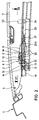
- a vehicle roof is denoted overall by 1, which has a roof opening which can be optionally closed or at least partially released by means of two cover elements.
- the cover elements are formed by a wind deflector blade 2 and a sliding cover 3 arranged behind it in the direction of travel.
- the wind deflector lamella 2 is pivotally connected near its front edge with a pivot axis 4 laterally in the area of the roof opening to the fixed vehicle roof.
- it is connected to an opening mechanism 6 via a bolt 5 arranged near its rear edge.
- the opening mechanism 6 comprises an opening lever 7 which is pivotally connected to a front auxiliary sliding element 13 at its end opposite the bolt 5 by means of a bolt 12.
- the deployment lever 7 has a longitudinal slot 8, in which a sliding block 9 slidably engages.
- the sliding block 9 is in turn connected by means of a bolt 10 to a bearing block 11 which is laterally attached to the fixed vehicle roof.
- the front auxiliary sliding element 13 is displaceably guided in a guide rail 18 extending laterally to the roof opening. It has a slot 14 running perpendicular to the direction of movement in the guide rail 18, in which a front sliding block 15 is slidably mounted perpendicular to the guide rail 18.
- the front locking block 15 has, on its front surface in the direction of travel, an upper control flank 16 which is inclined backwards at the top and a lower control flank 15 which is also inclined backwards at the bottom.
- a front sliding element 20 is arranged behind the front auxiliary sliding element 13 in the direction of travel.
- the front locking block 15 serves to forcibly couple and decouple the front auxiliary sliding element 13 and the front sliding element 20.
- the front locking block couples the front auxiliary sliding element 13 to the front sliding element 20, in which it has its lower part dips into a recess 21 on the front sliding element 20.
- a part of the guide rail 18 lies against the upper surface of the front locking block 15 and prevents the front locking block 15 from moving above.
- a recess 19 provided in the guide rail 18, on the other hand, enables the front locking block 15 to move upwards, which is from one with the lower one Control edge 17 cooperating unspecified control surface on the front sliding element 20 is effected.
- a locking slide 22 provided on the front sliding element 20 becomes active, which is arranged horizontally transversely to the direction of movement of the front auxiliary sliding element 13 and prevents the locking block 15 from moving moved down again.
- the locking slide 22 is described in detail below in connection with FIG. 7.
- the sliding cover 3 has near its front edge on the underside a front cover support 23 on which a bolt 24 is provided.
- the bolt 24 engages in a control link 25 running in sections parallel to the guide rail 18 and provided on the front sliding element 20.
- the control link 25 is composed of an inclined section 25B, which is inclined rearwards in the direction of travel and an adjoining straight section 25A, which extends parallel to the guide rail 18.
- the section 25A represents an empty path which the front sliding element 20 travels with respect to the bolt 24 during the deployment process of the wind deflector lamella 2. Due to the parallel arrangement of the straight section 25A with respect to the guide rail 18, the front edge of the sliding cover 3 is not yet lowered in this area.
- the front sliding element 20 is connected to a pressure and tensile drive cable 27 guided in a channel of the guide rail 18 and can be actuated by this with a manual or motor drive.
- the drive cable 27 is also fastened to a rear auxiliary sliding element 26 which is likewise arranged to be longitudinally displaceable in the guide rail 18.
- a rear sliding element 33 is arranged behind the rear auxiliary sliding element 26 in the direction of travel, to which a lowering mechanism for the sliding cover 3 is articulated.
- the rear sliding element 33 has a slot 34 running perpendicular to the guide rail 18, in which a rear sliding block 30 is arranged so as to be displaceable perpendicular to the direction of movement of the rear sliding element 33.
- the rear block 30 engages completely closed roof (Fig. 3) with its upper part in a recess 29 which is provided on the guide rail 18. Since it is simultaneously in engagement with the rear sliding element 33 with its central region, the rear locking block 30 couples this to the fixed vehicle roof 1 when the sliding cover 3 is closed.
- the sliding cover 3 is provided near its rear edge on the underside with a rear cover carrier 35, to which a bolt 36 is attached.
- the bolt 36 is pivotally connected to a lever 37 which is pivotally connected to the rear sliding element 33 at its opposite end via a bolt 38.
- the lever 37 also has a control pin 39 which interacts with a roof-mounted lifting link 41, which is arranged together with a stop 42 arranged in the closed position below the control pin 39 on a control part 43 connected to the guide rail 18.
- the control part 43 also has an arcuate control link 40 which runs from top to back and guides the pin 36.
- FIG. 7 the front sliding element 20 and the front auxiliary sliding element 13 are shown in a top view with the wind deflector lamella 2 closed and the sliding cover 3 closed.
- the front locking block 15 couples the front auxiliary sliding element 13 to the front sliding element 20.
- the locking slide 22 is spring-biased by a compression spring 45 in the direction of the locking block 15.
- the front sliding element 20 pulls the front auxiliary sliding element 13 backwards via the locking block 15 (i.e. to the right in FIG. 7) until the locking block 15 comes under the recess 19 in the guide rail 18.
- the locking block 15 is forcibly brought into engagement with the recess 19 by the lower control flank 17 when the front sliding element 20 is moved further up.
- a sloping control surface 44 provided on the front of a projecting part of the front sliding element 20 enables a complementarily tapered control surface 22A on the locking slide 22 that it moves under the pressure of the Drock spring 45 towards the locking block 15 and finally engages under it, so that the locking block 15 is held in engagement with the recess 19.
- the control surface 44 presses the locking slide 22 inward against the spring pressure via the control surface 22A, so that this again releases a movement of the locking block 15 downward for a coupling of the front auxiliary sliding element 13 and the front sliding element 20.
- the rear locking block 30 couples the rear sliding element 33 to the guide rail 18 by engaging in the recess 29.
- the front locking block 15 simultaneously couples the front auxiliary sliding element 13 to the front sliding element 20 by engaging in its recess 21. If not now Drive shown, the drive cable 27 to the rear, ie moved to the right in the drawings, the front sliding element 20 pulls the front auxiliary sliding element 13 behind.
- the deployment lever 7 ensures by moving the bolt 12 to the rear and the simultaneous engagement of the sliding block 9 pivotally coupled to the fixed bearing block 11 in the link slot 8 for setting up the rear edge of the wind deflector plate 2 in the position shown in FIG. 4.
- the front sliding member 20 travels an empty path corresponding to the straight portion 25A with respect to the bolt 24. Due to the simultaneous connection to the same drive cable 27, the rear auxiliary sliding element 26 is also moved backwards in the same time towards the rear sliding element 33.
- the front locking block 15 removes the coupling between the front auxiliary sliding element 13 and the front sliding element 20 and at the same time couples the front auxiliary sliding element 13 to the guide rail 18.
- the wind deflecting lamella 2 is thereby firmly locked to the guide rail in the fully extended position shown in FIG. 4.
- the rear locking block 30 releases the locking of the rear sliding element 33 with the guide rail 18 and, at the same time, couples the rear sliding element 33 to the rear auxiliary sliding element 26.
- the lowering mechanism on the rear edge of the lid becomes effective in the manner already described above .
- the rear auxiliary sliding element 26 pushes the rear sliding element 33 backwards until the sliding cover 3 has moved completely under the rear part of the fixed vehicle roof 1.
- the rear auxiliary sliding element 26 pulls the rear sliding element 33 forward through the coupling by means of the rear locking block 30 until the recess 29 in the guide rail 18 allows the rear locking block 30 to move upward above the rear locking block 30.
- a lower control flank 32 which is inclined obliquely forward on the rear flank of the rear locking block 30 on the underside is forcibly pressed upwards by a complementary surface on the rear auxiliary sliding element 26.
- the rear locking block 30 is thereby forcibly decoupled from the rear auxiliary sliding element 26 and at the same time couples the rear sliding element 33 to the recess 29 in the guide rail 18.
- control bolt 39 has run up onto the roof-mounted lifting link 41 to lift the rear edge of the cover and has inserted the bolt 36 into the control link 40 which is inclined downward and rearward.
- the lever 37 on which the rear edge of the lid is arranged above the bolt 36, is forcibly pivoted upward when the bolt 38 is pulled forward.
- the front sliding element 20 moves forward by a corresponding amount due to the coupling to the same drive cable 27, the front edge of the cover is raised upward in parallel by the movement of the bolt 24 along the inclined section 25B of the control link 25.
- the front locking block 15 is uncoupled from the recess 19 in the guide rail 18. This is done in that the front sliding element 20 runs against the front auxiliary sliding element 13, the upper control flank 16 from the complementary shaped flank of the recess 19 is pressed down. At the same time, the locking slide 22 opens and allows the locking block 15 to enter downward into the recess 21 in the front sliding element 20.
- the front auxiliary sliding element 13 and the front sliding element 20 are forcibly coupled to one another again during the further movement forwards to lower the wind deflector lamella 2.
Landscapes
- Engineering & Computer Science (AREA)
- Mechanical Engineering (AREA)
- Fittings On The Vehicle Exterior For Carrying Loads, And Devices For Holding Or Mounting Articles (AREA)
- Power-Operated Mechanisms For Wings (AREA)
Applications Claiming Priority (2)
| Application Number | Priority Date | Filing Date | Title |
|---|---|---|---|
| DE19505006 | 1995-02-15 | ||
| DE19505006A DE19505006C1 (de) | 1995-02-15 | 1995-02-15 | Fahrzeugdach mit zwei Deckelelementen |
Publications (2)
| Publication Number | Publication Date |
|---|---|
| EP0727331A1 true EP0727331A1 (fr) | 1996-08-21 |
| EP0727331B1 EP0727331B1 (fr) | 1998-07-15 |
Family
ID=7753998
Family Applications (1)
| Application Number | Title | Priority Date | Filing Date |
|---|---|---|---|
| EP96102063A Expired - Lifetime EP0727331B1 (fr) | 1995-02-15 | 1996-02-13 | Toit de véhicule avec deux panneaux |
Country Status (4)
| Country | Link |
|---|---|
| US (1) | US5601330A (fr) |
| EP (1) | EP0727331B1 (fr) |
| JP (1) | JP2889526B2 (fr) |
| DE (1) | DE19505006C1 (fr) |
Cited By (3)
| Publication number | Priority date | Publication date | Assignee | Title |
|---|---|---|---|---|
| WO2007028377A2 (fr) | 2005-09-09 | 2007-03-15 | Webasto Ag | Toit pour vehicule comprenant au moins deux elements de recouvrement |
| DE10105598B4 (de) * | 2001-02-06 | 2009-07-09 | Webasto Ag | Windabweiser für einen Kraftwagen |
| DE102010019300A1 (de) | 2010-05-04 | 2011-11-10 | Webasto Ag | Fahrzeugdach mit wenigstens einem Deckelelement |
Families Citing this family (28)
| Publication number | Priority date | Publication date | Assignee | Title |
|---|---|---|---|---|
| US5803534A (en) * | 1993-10-15 | 1998-09-08 | Dr. Ing. H.C.F. Porsche Ag | Passenger car with a transparent top assembly |
| DE19609188C1 (de) * | 1996-03-09 | 1997-04-24 | Webasto Karosseriesysteme | Betätigungsmechanik für ein öffnungsfähiges Fahrzeugdach |
| DE19634853C1 (de) * | 1996-08-28 | 1997-09-25 | Webasto Karosseriesysteme | Öffnungsfähiges Fahrzeugdach |
| DE19713360C1 (de) * | 1997-03-29 | 1998-04-23 | Webasto Karosseriesysteme | Vorrichtung zum Ausstellen eines verschwenkbaren Fahrzeug-Dachelements |
| DE19733871A1 (de) * | 1997-08-05 | 1999-02-11 | Bayerische Motoren Werke Ag | Windabweiser eines Fahrzeuges, insbesondere Personenkraftwagens |
| DE19738829C1 (de) * | 1997-09-05 | 1999-02-18 | Daimler Benz Ag | Aus zwei Dachteilen bestehende Dachanordnung |
| EP0919415B1 (fr) * | 1997-11-07 | 2004-02-04 | Inalfa Roof Systems Group B.V. | Construction de toit ouvrant pour véhicule |
| NL1009071C2 (nl) * | 1998-05-06 | 1999-11-09 | Inalfa Ind Bv | Open-dakconstructie voor een voertuig. |
| DE19907377B4 (de) * | 1999-02-20 | 2014-09-11 | Bayerische Motoren Werke Aktiengesellschaft | Schiebehebedach eines Personenkraftwagens mit insbesondere zwei Deckelteilen |
| NL1011862C2 (nl) * | 1999-04-22 | 2000-10-24 | Inalfa Ind Bv | Open-dakconstructie voor een voertuig. |
| US6199944B1 (en) | 1999-06-04 | 2001-03-13 | Asc Incorporated | Spoiler sunroof |
| US6174025B1 (en) | 1999-08-31 | 2001-01-16 | Daimlerchrysler Corporation | Sun roof air dam wind noise reducer |
| DE10011339B4 (de) * | 2000-03-10 | 2004-03-18 | Webasto Vehicle Systems International Gmbh | Fahrzeugdach mit zwei Deckeln |
| DE10011350B4 (de) * | 2000-03-10 | 2004-08-26 | Webasto Vehicle Systems International Gmbh | Fahrzeugdach mit zwei Deckeln und Himmel für ein derartiges Fahrzeugdach |
| US6565149B2 (en) | 2000-03-10 | 2003-05-20 | Webasto Vehicle Systems International Gmbh | Motor vehicle roof with two covers and a headliner for one such motor vehicle roof |
| NL1015394C2 (nl) | 2000-06-07 | 2001-12-10 | Inalfa Ind Bv | Open-dakconstructie voor een voertuig. |
| DE10137650A1 (de) * | 2001-08-03 | 2003-02-27 | Webasto Vehicle Sys Int Gmbh | Windabweiser für ein Fahrzeugdach |
| DE10151621B4 (de) * | 2001-10-23 | 2004-06-03 | Webasto Vehicle Systems International Gmbh | Vorrichtung zum Öffnen und Schließen einer Öffnung in einem Fahrzeugdach mit mindestens einem durch Führungsschienen geführten Deckel |
| JP2003237372A (ja) * | 2002-02-19 | 2003-08-27 | Aisin Seiki Co Ltd | 車両用ルーフ装置 |
| DE10217659B4 (de) * | 2002-04-19 | 2008-04-30 | Webasto Ag | Windabweiseranordnung |
| DE10218387B4 (de) * | 2002-04-24 | 2004-03-04 | Webasto Vehicle Systems International Gmbh | Öffnungsfähiges Fahrzeugdach |
| DE10232913B4 (de) * | 2002-07-19 | 2008-01-24 | Webasto Ag | Vorrichtung zum Beeinflussen der Luftströmung im Bereich einer Dachöffnung eines öffnungsfähigen Fahrzeugdaches |
| FR2861019B1 (fr) * | 2003-10-20 | 2008-01-04 | France Design | Dispositif de deflexion d'air pour vehicule a toit ouvrant |
| DE102004030804B3 (de) * | 2004-06-25 | 2006-01-05 | Webasto Ag | Windabweiser |
| DE102006022822B3 (de) * | 2006-05-12 | 2007-12-20 | Rausch & Pausch Gmbh | Antriebsanordnung für ein Fahrzeugdachsystem |
| CN102264566B (zh) * | 2008-11-17 | 2014-04-02 | 银娜珐天窗系统集团股份有限公司 | 可移动的挡风板 |
| DE202009018695U1 (de) | 2009-01-27 | 2012-11-21 | Webasto Ag | Fahrzeug-Außenflächenbauteil mit Glasoptik |
| EP3795397B1 (fr) | 2019-09-17 | 2023-11-01 | Inalfa Roof Systems Group B.V. | Ensemble déflecteur d'air |
Citations (4)
| Publication number | Priority date | Publication date | Assignee | Title |
|---|---|---|---|---|
| GB2147943A (en) * | 1983-09-29 | 1985-05-22 | Johnan Seisakusho | Sunroof panel opening/closing apparatus |
| GB2174047A (en) * | 1985-04-15 | 1986-10-29 | Gilardini Spa | Sun roof for vehicles |
| GB2199797A (en) * | 1986-12-23 | 1988-07-20 | Gilardini Spa | A sun roof for vehicles |
| GB2251223A (en) * | 1990-12-20 | 1992-07-01 | Rockwell Golde Gmbh | Sliding roof for an automobile |
Family Cites Families (3)
| Publication number | Priority date | Publication date | Assignee | Title |
|---|---|---|---|---|
| JPH01257622A (ja) * | 1988-04-07 | 1989-10-13 | Daihatsu Motor Co Ltd | 自動車のセパレートサンルーフ |
| JPH03121926A (ja) * | 1989-10-03 | 1991-05-23 | Honda Motor Co Ltd | 自動車用サンルーフ装置 |
| DE4200724C1 (fr) * | 1992-01-14 | 1992-12-24 | Rockwell Golde Gmbh, 6000 Frankfurt, De |
-
1995
- 1995-02-15 DE DE19505006A patent/DE19505006C1/de not_active Expired - Lifetime
-
1996
- 1996-01-30 US US08/594,236 patent/US5601330A/en not_active Expired - Fee Related
- 1996-02-08 JP JP8022761A patent/JP2889526B2/ja not_active Expired - Fee Related
- 1996-02-13 EP EP96102063A patent/EP0727331B1/fr not_active Expired - Lifetime
Patent Citations (4)
| Publication number | Priority date | Publication date | Assignee | Title |
|---|---|---|---|---|
| GB2147943A (en) * | 1983-09-29 | 1985-05-22 | Johnan Seisakusho | Sunroof panel opening/closing apparatus |
| GB2174047A (en) * | 1985-04-15 | 1986-10-29 | Gilardini Spa | Sun roof for vehicles |
| GB2199797A (en) * | 1986-12-23 | 1988-07-20 | Gilardini Spa | A sun roof for vehicles |
| GB2251223A (en) * | 1990-12-20 | 1992-07-01 | Rockwell Golde Gmbh | Sliding roof for an automobile |
Cited By (5)
| Publication number | Priority date | Publication date | Assignee | Title |
|---|---|---|---|---|
| DE10105598B4 (de) * | 2001-02-06 | 2009-07-09 | Webasto Ag | Windabweiser für einen Kraftwagen |
| WO2007028377A2 (fr) | 2005-09-09 | 2007-03-15 | Webasto Ag | Toit pour vehicule comprenant au moins deux elements de recouvrement |
| US7762623B2 (en) | 2005-09-09 | 2010-07-27 | Webasto Ag | Vehicle roof with at least two cover elements |
| DE102010019300A1 (de) | 2010-05-04 | 2011-11-10 | Webasto Ag | Fahrzeugdach mit wenigstens einem Deckelelement |
| DE102010019300B4 (de) * | 2010-05-04 | 2014-06-05 | Webasto SE | Fahrzeugdach mit wenigstens einem Deckelelement |
Also Published As
| Publication number | Publication date |
|---|---|
| US5601330A (en) | 1997-02-11 |
| EP0727331B1 (fr) | 1998-07-15 |
| DE19505006C1 (de) | 1996-04-04 |
| JPH08244463A (ja) | 1996-09-24 |
| JP2889526B2 (ja) | 1999-05-10 |
Similar Documents
| Publication | Publication Date | Title |
|---|---|---|
| EP0727331B1 (fr) | Toit de véhicule avec deux panneaux | |
| EP1112881B1 (fr) | Dispositif de verrouillage pour toit pliant | |
| EP2451665B2 (fr) | Dispositif de toit ouvrant, en particulier pour un véhicule automobile | |
| EP3386787B1 (fr) | Toit ouvrant de véhicule, comprenant une cinématique de déplacement à bielle | |
| DE102005007031B4 (de) | Fahrzeugdach mit einem oberhalb des Daches verschiebbaren Dachteil | |
| DE102006002064B4 (de) | Fahrzeugdach mit einem oberhalb eines festen Dachabschnitts verschiebbaren Deckel | |
| DE4407286C1 (de) | Fahrzeugdach mit einer Folge von Lamellen | |
| EP1060923A2 (fr) | Toit de véhicule | |
| DE3442631A1 (de) | Schiebehebedach | |
| DE19700165C2 (de) | Schiebehebedach | |
| DE10117322A1 (de) | Fahrzeugdach | |
| WO2008017294A1 (fr) | Toit ouvrant de véhicule avec dispositif modulaire de déplacement et de guidage | |
| DE4238945C1 (de) | Hebeschiebedach für Fahrzeuge | |
| EP1129879B1 (fr) | Dispositif d'actionnement pour le déplacement d' un panneau de toit coulissant pour véhicule | |
| EP1851080A1 (fr) | Toit de vehicule comprenant une partie de toit pouvant etre deplacee au-dessus du toit | |
| EP2129540B1 (fr) | Toit ouvrant de véhicule avec un dispositif d'actionnement pour un élément mobile de toit | |
| DE10158174B4 (de) | Schiebehebedach für Fahrzeuge | |
| EP1216869B1 (fr) | Toit ouvrant pour véhicule | |
| DE4329580C1 (de) | Fahrzeugdach mit einer Folge von Lamellen | |
| EP1834820A1 (fr) | Toit panoramique | |
| EP1922220B1 (fr) | Toit pour vehicule comprenant au moins deux elements de recouvrement | |
| DE102006051109B4 (de) | Fahrzeugdach mit einem bewegbaren Dachteil | |
| DE19539085A1 (de) | Verriegelung für ein schwenkbares Dachteil eines Fahrzeuges | |
| DE19856873C1 (de) | Lamellendach für eine Dachöffnung eines Kraftfahrzeugs | |
| DE19609188C1 (de) | Betätigungsmechanik für ein öffnungsfähiges Fahrzeugdach |
Legal Events
| Date | Code | Title | Description |
|---|---|---|---|
| PUAI | Public reference made under article 153(3) epc to a published international application that has entered the european phase |
Free format text: ORIGINAL CODE: 0009012 |
|
| 17P | Request for examination filed |
Effective date: 19960515 |
|
| AK | Designated contracting states |
Kind code of ref document: A1 Designated state(s): FR GB IT |
|
| GRAG | Despatch of communication of intention to grant |
Free format text: ORIGINAL CODE: EPIDOS AGRA |
|
| GRAG | Despatch of communication of intention to grant |
Free format text: ORIGINAL CODE: EPIDOS AGRA |
|
| GRAH | Despatch of communication of intention to grant a patent |
Free format text: ORIGINAL CODE: EPIDOS IGRA |
|
| 17Q | First examination report despatched |
Effective date: 19971127 |
|
| GRAH | Despatch of communication of intention to grant a patent |
Free format text: ORIGINAL CODE: EPIDOS IGRA |
|
| GRAA | (expected) grant |
Free format text: ORIGINAL CODE: 0009210 |
|
| AK | Designated contracting states |
Kind code of ref document: B1 Designated state(s): FR GB IT |
|
| GBT | Gb: translation of ep patent filed (gb section 77(6)(a)/1977) |
Effective date: 19980716 |
|
| ET | Fr: translation filed | ||
| PLBE | No opposition filed within time limit |
Free format text: ORIGINAL CODE: 0009261 |
|
| STAA | Information on the status of an ep patent application or granted ep patent |
Free format text: STATUS: NO OPPOSITION FILED WITHIN TIME LIMIT |
|
| 26N | No opposition filed | ||
| REG | Reference to a national code |
Ref country code: GB Ref legal event code: IF02 |
|
| PGFP | Annual fee paid to national office [announced via postgrant information from national office to epo] |
Ref country code: FR Payment date: 20140218 Year of fee payment: 19 Ref country code: IT Payment date: 20140225 Year of fee payment: 19 |
|
| PGFP | Annual fee paid to national office [announced via postgrant information from national office to epo] |
Ref country code: GB Payment date: 20140220 Year of fee payment: 19 |
|
| GBPC | Gb: european patent ceased through non-payment of renewal fee |
Effective date: 20150213 |
|
| REG | Reference to a national code |
Ref country code: FR Ref legal event code: ST Effective date: 20151030 |
|
| PG25 | Lapsed in a contracting state [announced via postgrant information from national office to epo] |
Ref country code: IT Free format text: LAPSE BECAUSE OF NON-PAYMENT OF DUE FEES Effective date: 20150213 |
|
| PG25 | Lapsed in a contracting state [announced via postgrant information from national office to epo] |
Ref country code: GB Free format text: LAPSE BECAUSE OF NON-PAYMENT OF DUE FEES Effective date: 20150213 |
|
| PG25 | Lapsed in a contracting state [announced via postgrant information from national office to epo] |
Ref country code: FR Free format text: LAPSE BECAUSE OF NON-PAYMENT OF DUE FEES Effective date: 20150302 |