EP1060923A2 - Toit de véhicule - Google Patents
Toit de véhicule Download PDFInfo
- Publication number
- EP1060923A2 EP1060923A2 EP00112517A EP00112517A EP1060923A2 EP 1060923 A2 EP1060923 A2 EP 1060923A2 EP 00112517 A EP00112517 A EP 00112517A EP 00112517 A EP00112517 A EP 00112517A EP 1060923 A2 EP1060923 A2 EP 1060923A2
- Authority
- EP
- European Patent Office
- Prior art keywords
- roof
- vehicle
- roof part
- locking
- cassette
- Prior art date
- Legal status (The legal status is an assumption and is not a legal conclusion. Google has not performed a legal analysis and makes no representation as to the accuracy of the status listed.)
- Granted
Links
Images


Classifications
-
- B—PERFORMING OPERATIONS; TRANSPORTING
- B60—VEHICLES IN GENERAL
- B60J—WINDOWS, WINDSCREENS, NON-FIXED ROOFS, DOORS, OR SIMILAR DEVICES FOR VEHICLES; REMOVABLE EXTERNAL PROTECTIVE COVERINGS SPECIALLY ADAPTED FOR VEHICLES
- B60J7/00—Non-fixed roofs; Roofs with movable panels, e.g. rotary sunroofs
- B60J7/0053—Collapsible lateral roof side beams
-
- B—PERFORMING OPERATIONS; TRANSPORTING
- B60—VEHICLES IN GENERAL
- B60J—WINDOWS, WINDSCREENS, NON-FIXED ROOFS, DOORS, OR SIMILAR DEVICES FOR VEHICLES; REMOVABLE EXTERNAL PROTECTIVE COVERINGS SPECIALLY ADAPTED FOR VEHICLES
- B60J7/00—Non-fixed roofs; Roofs with movable panels, e.g. rotary sunroofs
- B60J7/02—Non-fixed roofs; Roofs with movable panels, e.g. rotary sunroofs of sliding type, e.g. comprising guide shoes
- B60J7/06—Non-fixed roofs; Roofs with movable panels, e.g. rotary sunroofs of sliding type, e.g. comprising guide shoes with non-rigid element or elements
- B60J7/061—Non-fixed roofs; Roofs with movable panels, e.g. rotary sunroofs of sliding type, e.g. comprising guide shoes with non-rigid element or elements sliding and folding
Definitions
- the invention relates to a vehicle roof with at least one of one Drive motor operable openable roof part and at least one temporarily fixed roof part, which the openable roof part in its Open position.
- an electric drive is arranged, which Unlocking the side rails from the cross member causes a second electrical Drive in the rear roof part takes over the shifting of the openable Roof part and another, also attached in the area of the rear roof part electric drive serves to pivot the side rails. Furthermore, a Hydraulic cylinder in the area of the rear vehicle side walls available for a pivoting of the rear roof part together with that of the rear Roof part of the openable roof part, attached to the rear roof part pivoted side rails and rear pillars (C pillars) on which the rear roof part rests on both sides, ensures.
- the invention specified in claim 1 is based on the object To create vehicle roof of the type mentioned, without an expensive Actuating mechanism works, convenient to use and universal can be used.
- the temporarily fixed roof part is preferably a rear roof part and the at least temporarily fixed roof part especially around the rear side pillars (B or C pillars) of the vehicle.
- the openable can be used to increase the operational safety of the vehicle roof Roof part can be locked in the open position in the temporarily fixed roof part, the locking of the openable roof part in the temporarily fixed Roof part is preferably operated by the drive motor.
- the design effort of the vehicle roof can be kept low if the Drive motor is fixed on the temporarily fixed roof part.
- the rear roof part is temporary fixed roof part after unlocking it at least temporarily fixed roof part, especially after unlocking from the rear pillars (B or C pillars), can be lowered.
- the rear roof section can be made using a Four-bar arrangement are lowered, preferably to the extent that one Top of the rear roof part at about the level of the belt line of the vehicle comes to lie.
- the temporarily fixed Roof part after it has been unlocked from the at least temporarily fixed roof part completely removed from the vehicle.
- the rear pillars of the vehicle can be lowered, one can Convertible roof opening without the belt line protruding upwards Body parts in the rear area of the vehicle are released.
- an automatic extension of the rear pillars can be provided, as soon as an electronic monitoring device threatens to roll over of the vehicle registered.
- the drive motor which is used to actuate the opening and closing movement of the openable roof part and for actuating the lock and / or Unlocking the temporarily fixed roof part with respect to the at least temporarily used roof part can also be used to operate a Locking the rear roof part in the lowered position and / or a release same from the lowered position.
- Actuated in particular the drive motor is a locking device, which is preferably at times fixed roof part is fixed and not only the locking / unlocking of the temporarily fixed roof part with respect to the at least temporarily fixed roof part, but also with reference, for example, to the Lowering movement of the temporarily fixed roof part Four-joint arrangement is used.
- at least at times fixed roof part and arranged a counter bearing on the four-bar arrangement be, which interacts with the closure device.
- a rear part of the vehicle can be fixed on the rear roof part includes a rear window. If the rear roof section is designed to be lowerable, then so the rear window is preferably made of a foldable plastic material.
- Is an underside of the rear part of the vehicle attached to the rear roof part Can be placed on a rear door of the vehicle and folded upwards in particular the accessibility to one located in the area of the rear of the vehicle Improve storage space.
- the openable roof part can be a while driving Openable roof part like a folding roof or a lamella roof in principle act in a known manner. It is understood that within the scope of the present Invention as an openable roof part also a sunroof or Sunroof with one or more lids, preferably with two Lids that can be used.
- a vehicle 10 with a vehicle roof 1 which a drive motor designed as an electric motor 222 openable roof part, a temporarily fixed roof part, at least one temporarily fixed roof part, a rear part 6 and side rails 28 includes.
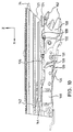
- the openable roof part is a folding roof 30, which in guides of the temporarily fixed roof part and in those of the side rails 28 in opening or Closing direction 32 slidably received and in any Intermediate positions between its open position (see FIGS. 2, 3 and 5) and its closed position (see FIGS. 1 and 6) can be brought.
- Folding roof 30 in the temporarily fixed roof part which in the illustrated embodiment designed as a roof cassette 12 rear roof part of the vehicle roof 1 is mounted, all in the guides displaceable parts of the folding roof 30 arranged in the roof cassette 12 Guides are included and can be locked with reference to the roof cassette 12, as described below in connection with FIGS. 7 to 12 is explained in more detail.
- the folding roof 30 is in the open position as far back in the opening direction 32 moved that its rooftop 149 is essentially flush with one Front edge of the roof cassette 12 closes.
- the guides arranged in the roof cassette 12 are by Guide rail sections 22 formed on the locking devices 14th are attached, which in turn are fixed to the roof cassette 12, the Guide rail sections 22 with front guide rail sections 26 in Alignment if the roof cassette 12 at least temporarily with respect to that fixed roof part is locked.
- the front guide rail sections 26 form the existing guides in the side rails 28 and are floating in the side rails 28 added.
- the side rails 28 are detachable with the Vehicle 10 connected, for which purpose in the area of the joint between a front, above the windshield crossmember 2 and front side Pillars (A pillars 3) front side rail bearing 13 and in the area of the upper End of an at least temporarily fixed additional roof part rear pillars (B pillars 20) rear side rail bearings 15 are provided.
- the expanded Side rails 28 can be in the vehicle 10 in corresponding Place cradles, for example in a tailgate 5.
- the rear side pillars i.e. the B-pillars 20, at least temporarily fixed roof part.
- a rear cross member 4 in the manner of a roll bar extend.
- One closure device 14 is on the attached to the left and right side of the roof cassette 12 in the direction of travel and interacts with a counter bearing 11 which is close to an upper end of each of the B-pillars 20 is fixed to be actuated via the electric motor 222 Locking and unlocking the roof cassette 12 with respect to the B-pillars 20 to effect.
- the rear part 6 of the vehicle roof 1 is fixed to the roof cassette 12 and includes a rear window 18 made of foldable plastic material as well foldable side parts 16.
- the roof cassette 12 is over a not shown Four-joint arrangement connected to the vehicle body and after unlocking from the counter bearing 11 of the B-pillars 20 so far that an upper side of the Roof cassette 12 to lie essentially at the level of the vehicle belt line is coming.
- the Four-joint arrangement itself also provided a counter bearing, with which the Locking device 14 in a similar manner as with the counter bearing 11 interacts.
- An underside 7 of the rear part 6 can be placed against a rear door 5 and can, as shown in Fig.
- the tailgate 5 in turn, its underside is pivotally connected to the vehicle body and can be independent of the position which the underside 7 of the rear part 6 occupies and also folded back with the roof cassette 12 lowered become.
- a Lock latch for the tailgate 5 can be on the bottom 7 of the rear part 6
- Cross member may be arranged.
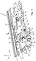
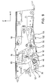
- FIGS. 7 to 12 two embodiments of the Closure device 14 described in detail, with two on the roof cassette 12 mirror-image closure devices are attached, but only the Left closure device 14 seen in the direction of travel in the figures is reproduced. All versions regarding the left locking device 14 also refer to the mirror image rights Locking device. It should also be noted that the in Fig. 7 to 11 with X designated axis in the opening direction of the folding roof 30, i.e. in the same Direction as the arrow 32 pointing towards the vehicle in FIG. 2 points.
- the two closure devices are symmetrical to one in Vehicle longitudinal axis of symmetry inside the roof cassette 12 mounted near their lateral outer surfaces in such a way that they are attached to the other B pillars 20 attached counter bearings 11 can be set, wherein at the same time with the guide rail sections 22 of the closure devices 14 the front guide rail sections 26 of the side rails 20 in alignment be aligned by one fixed on the guide rail section 22 Alignment bar 24 as an alignment member in engagement with the front Guide rail sections 26 is brought.
- the closure device 14 comprises a bearing plate 34 with an as Recording groove 48 trained receiving member into which a bolt 46 of the the B-pillar 20 attached counter bearing 11 in the direction of displacement 50 (see FIG. 9) inserted and by means of a locking groove 42 of a locking hook 36 can be locked.
- the locking groove 42 is in a front arm 38 of the locking hook 36 is placed, which is pivotable about a bearing pin 56 in a bent bearing lever 58 is added.
- the bearing pin 56 of the Locking hook 36 is approximately in the middle between which the locking groove 42 comprising front arm 38 and a rear arm 40, the Locking hook 36 about the axis of the bearing pin 56 in the pivoting direction 44 (see Fig. 7) between one in Figs. 7, 9 and 10 shown locking and a release position is pivotable, in the locked position Locking hook 36 also between a broken line in Fig. 9 reproduced front locking position 52 and a rear locking position 54 in Sliding direction 50 slidable.
- the bearing lever 58 is formed in two parts and comprises two in the Y direction Thickness of a sleeve 62 spaced congruent halves, the spacing so is dimensioned that the locking hook 36 and one described below Control lever 84 can be added between them.
- the socket 62 is open an axis 60 slid on the arm 64 of the bearing lever 58 in the Y direction enforced that it projects beyond the halves of the bearing lever 58 on both sides and on the one hand in the bearing plate 34 and on the other hand in an arm 64 encompassing bearing bracket 59 is held, which in turn on the bearing plate 34th is set.
- the bearing lever 58 is by means of one on its second arm 66 fixed control pin 68 pivotable about the axis 60, the control pin 68 protrudes beyond the bearing lever in the Y direction and into a control track 72 Switching slot 74 engages in which it is guided over a sliding block 70.
- the switching link 74 is integrated in a link body 80, the second Has shifting gate 78, in the control path 76 thereof on the control lever 84 fixed control pin 82 is slidably received and its Swiveling movement about the axis of the bearing pin 56 causes by means of Control lever 84 together with the locking hook 36 in the bearing lever 58 is mounted, the control lever in the direction of the front arm 38 of the Locking hook 36 extends.
- a bend 92 of the control lever 84 engages a recess 85 of the locking hook 36 which is open in the -Z direction and serves to carry the locking hook 36 when the control lever 84 over its control pin 82 is pivoted clockwise by the control track 78 (The terms used clockwise and counterclockwise each refer to an observation in the Y direction).
- a holding lever 89 is pivotable approximately in the middle by a shoulder bolt 91 on the Locking hook 36 in the area between the recess 85 and the Locking groove 42 mounted, with a tension spring 90 between one on one first arm 93 of the holding lever 89 located projection 88 and a bend 86 of the control lever 84 is provided.
- the in first arm 93 of the holding lever 89 above a substantially in the X direction open locking area 98 arranged inclined surface 95 is formed such that about the prestressed contact of the inclined surface 95 on the retaining bolt 87 Force is exerted on the locking hook 36, the latter in Counterclockwise around the axis of the bearing pin 56 rotates, and the Locking hook 36 seen in the longitudinal direction of the vehicle 10 located behind the locking groove 42 (i.e., starting from the locking groove 42 offset in the positive X direction), 50 in the displacement direction extending sliding surface 190 rests on a bend 188 of the bearing plate 34.
- the Retaining pin 87 also serves as a catching device into which the latching area 98 of the Holding lever 89 engages when the locking hook 36 is in its Release position is.
- a second arm 94 of the holding lever 89 which is located below the shoulder bolt 91 (i.e., offset with respect to this in the negative Z direction), has an im Projection 97 projecting substantially in the X direction, which in order to Control lever 84 set with respect to the locking hook 36 to one Bottom of the bend 92 of the control lever 84 can be applied as soon as the Locking hook 36 approaches its rear latching position 54.
- a total of 100, essentially in the X direction extending alignment plate is with the bearing plate 34 via a plurality of screws 99 connected, which is simultaneously a lower area of the guide rail section 22, which also has blind rivets (not shown) in its upper section Area is fixed directly to the bearing plate 34, with a solid cohesion achieved by bearing plate 34, guide rail section 22 and alignment plate 100 becomes.
- the guide rail section 22 has a lower and an upper slideway 101 or 102, which by a partition 104 extending in the X-Z plane are separated from each other.
- the lower slideway 101 is laterally from the partition 104 and a rear wall of the bearing plate 34 and up and down through Legs that extend from the partition 104 in the -Y direction, limited and open in +/- X direction.
- the link body 80 is in the +/- X direction slidable between a rear and a front end position.
- the slideway 102 is up and down by extending in the Y direction Limits 112 and 110 and by means of perpendicular to the legs 110 and 112 arranged webs 109 divided into at least two open chambers 111, 113, of which the inner chamber 111 of receiving a driving slider 114 and the outer chamber 113 serves to receive a roof glider 116.
- Both Gliders 114 and 116 can be moved in the +/- X direction, with the driving glider 114 the pressure-resistant cable 174 is attached, which over the on the Roof cassette 12 fixed electric motor 222 (see FIG. 2) is movable and in a cable duct 118 is guided, the side next to the slideway 102 in the Partition 104 is added.
- a tactile slide 120 which can be displaced in the +/- X direction as part of a Counter bearing detection device added by the action of an intermediate the slide slider 120 and the alignment plate 100 attached tension spring 122 in the -X direction is biased such that its stylus tip 124 has a leading edge 125 of the guide rail section 22 protrudes.
- a release 126 arranged with a release arm 128 of a bent locking lever 130 interacts, which in turn is pivotable about an axis 131 between the Bearing plate 34 and the alignment plate 100 is mounted.
- a locking lug 133 is provided, which is designed in a complementary shaped, not shown leading edge on the underside of the Link body 80 to engage when the link body 80 is in a behind warning position located in its front end position.
- the Warning position of the link body 80 with respect to the bearing plate 34 on a Place arranged between the front and rear end positions of the Link body 80 is located the front end position of a smaller X coordinate corresponds to the rear end position.
- the locking lever 130 is by means of a spring arm 134 a two spring arms 134 and 136 comprehensive combination spring 138 loaded counterclockwise, so that the Locking lug 133 biased when the link body 80 is in the warning position bears against its leading edge and prevents the link body 80 from being reaches the front end position if the counter bearing 11 is not in its desired position Regarding the closure device 14 is located.
- the backdrop body is in this Fall only between its rear end position and its warning position.
- the second spring arm 136 of the Combi spring 138 is biased upwards in the Z direction and can counteract it Bias down from the rear arm 40 of the locking hook 36 be deflected when the locking hook 36 is in its release position located.
- the spring arm 136 is biased in its upward direction Home position actuated an electrical microswitch 140, which together with the Combination spring 138 is fixed to the bearing plate 34, the microswitch 140 being a Corresponding signal "locking hook in locking position" delivers.
- This The signal is used as an input variable in a motorized operation of the Electronic control 218 controlling closure device 14 (see FIG. 13) fed, which also control the motorized operation of the opening and Closing movement of the folding roof 30 takes over.
- the spring arm 136 instead of its resilient Preload upwards with the rear arm 40 of the To connect locking hook 36 so that the latter the spring arm 136 in both Directions, i.e., up and down, operated.
- the tactile glider 120 when Coupling process of the closure device 14 to the counter bearing from Side spar 28 operated and moved in the X direction so far that the Locking lug 133 of the locking lever 130 no longer holds the link body 80 in its Warning position locked.
- the side rail 28 is removed from the vehicle or for some other reason it is not in its target position with respect to the locking device 14 in the coupling position, the probe tip 124 at Coupling process not operated or not operated far enough in the X direction and the Link body 80 locked when it reaches its warning position, even if that Counter bearing is in the target position.
- the counter bearing detection device used in principle for side post recognition. This has the further advantage that when coupling the closure device 14 to the further counter bearing, which is attached to the four-bar linkage, the link body 80 no further than into it Warning position can be moved, because that is at the four-bar linkage The intended counter bearing is in the target position, but a side rail is not available is. This prevents the locking of the Rooftop glider 116 is released with respect to the closure device 14, when the locking device 14 is coupled to the counter bearing of the four-bar linkage becomes.
- An alignment fork 152 at a front end of the alignment plate 100 is used for Alignment of the closure device 14 in the Y and Z directions with respect to the front guide rail section 26, for which purpose the alignment fork 152 engages in a complementarily shaped alignment bearing, which is a unit with the front guide rail section 26 floating in the side rail 28 forms.
- the on the guide rail section 22 of the closure device 14 fixed alignment bar 24, which is in the Z direction above the alignment fork 152 is located and brought into engagement with the front guide rail section 26 prevents tilting around the X axis of the front Guide rail section 26 with respect to the guide rail section 22.
- An alignment surface 150 is on a side surface of the alignment fork 152 in the X-Z plane located and on the end face of the bolt 46 on the B-pillar 20th attached counter bearing 11 can be applied, so that in cooperation with the mirror-image right locking device and the right bolt one in the Y direction seen symmetrical alignment of the entire roof cassette 12 with Reference is made to the two bolts 46 of the counter bearing 11.
- End position spring 146 which comprises two spring arms 142 and 144, one of which the spring arm 142 engages from below into the chamber 113 in which the Rooftop glider 116 is included, which with a rooftop 149 of the Folding roof 30 is connected and the opening and closing movement of the same causes.
- the second spring arm 144 is designed, an electrical microswitch 148 to operate mechanically when the Dachspitze glider 116 in a Stop position, the microswitch 148 the signal "Dachspitzeglider in Stop position "to the electronic control 218 (see FIG. 13).
- the rooftop glider 116 is fully in that position Guide rail section 22 of the closure device 14 and can be locked with respect to the guide rail section 22. With the Dachspitzengliter 116 are all movable parts of the folding roof 30 in the Guide rail section 22 held and together with the roof cassette 12th be decoupled from the counter bearing 11.
- the controller 218 receives for the vehicle roof in addition to the signals of two switch positions ("open” and “close") having actuating switch 224 also the signals of two sensors 226 and 228 as input variables.
- the operating switch 224 can be operated by the operator and serves to initiate both the opening and closing movement of the folding roof as well as the coupling and uncoupling movement of the closure device, with about the swiveling and sliding movements of the locking hook Locking and unlocking the roof cassette 12 with respect to the counter bearing 11 on the B-pillars 20 is effected.
- Two actuation switches can be provided, one of which is the opening and Closing movement of the folding roof and one when the folding roof is fully open initiates the coupling and uncoupling movement of the closure device.
- Both both sensors 226 and 228 are in the case of the first embodiment the locking device (shown in FIGS. 7 to 11) around the microswitch 148 or 140.
- an inductive sensor 216 is used.
- the roof tip glider 116 and the Driving sliders 114 in the front guide rail section 26 and positively connected to one another by means of a locking block 164, in the Z direction is slidably received in the roof tip glider 116.
- the Roof cassette 12 is on the locking devices 14 on the B-pillars 20 of the Vehicle 10 fixed, the locking hook 36 in Locking position stops in its rear latching position 54.
- the backdrop body 80 is in its front end position and is in this in the Y direction Slidably mounted locking block 156, which by means of a compression spring 160 loaded ball 158 can be locked in its end positions, in a recess 162 Bearing plate 34 held.
- the control pin 82 is Control lever 84 in a holding area 206 of the control track 76 for the Pivoting movement of the locking hook 36 responsible shifting gate 78.
- Der Retaining lever 89 is by abutting its inclined surface 95 on the retaining bolt 87 pivoted counterclockwise so far that its projection 97 the bend 92 of the control lever 84 engages and this with reference to the Locking hook 36 sets.
- the locking hook 36 is ultimately in his Locked position blocked. So that the backdrop body 80 in its front End position must, of course, as described above Counter bearing 11 or the side rail 28 are in the desired position, the key slide 120 actuated and the locking lug 133 of the locking lever 130 out of engagement with respect to the be arranged on the underside of the link body 80 leading edge.
- the folding roof 30 can be opened by the roof tip glider 116 in the opening direction 32 is moved behind.
- the sliding movement becomes the rooftop glider 116 impressed by the slider 114, which in turn by means of the known per se rigid cable 174 is moved over the electric motor 222, which in the Roof cassette 12 is added.
- Both the rooftop glider 116 and the Carriage gliders 114 eventually get from the front Guide rail section 26 in the guide rail section 22 of the Locking device 14, the roof tip glider 116 as soon as it is in its Stop position is reached, abuts a stop 168, which in the Guide rail section 22 is provided and a further displacement of the Rooftop glider 116 prevented to the rear (in the X direction) (see Fig. 11), wherein also, as described above, the electrical microswitch 148 from the spring arm 144 is operated.
- the driving glider 114 now has its one shown in FIG. 11 Transfer position reached.
- the operator continues to operate the switch position "Opening" of the actuation switch 224, then at the control 218 applied signal "rooftop glider in stop position" of the microswitch 148 the Decoupling movement of the closure device initiated, namely preferably only after certain safety conditions have been met. For this can e.g. count that the vehicle may not be moved and / or that the Operator operates switch 224 during a predetermined actuation time must hold in the "Open" switch position.
- the entrainment slider 114 When the uncoupling process is initiated, the entrainment slider 114 first becomes from the electric motor 222 via the compression-resistant cable 174 with a force in the X direction applied so that an inclined surface 170 in the locking block 164th receiving recess 166 in the driving slider 114 a force in the Z direction exercises on the bolt 164, which is sufficient, the latter so far in the Z direction move the latch 164 out of engagement with respect to the recess 166 arrives in the driving glider 114 and with it the driving glider 114 opposite end into a recess 172 in the guide rail section 22 is pushed.
- the roof top glider 116 is thus positively in the Guide rail section held, and the driving slider 114 for another Displacement in the X direction is released, the roof tip glider 116 facing side of the driving slider 114 is designed so that a release of the Positive connection between the roof tip glider 116 and the Guide rail section 22 by moving the locking block 164 in Rooftop glider 116 in the -Z direction is excluded.
- the driving glider 114 comes by means of its Coupling surface 176 on the leading edge 108 of the in the front end position according to Fig.
- the Riegelstein 156 releases the positive connection of the link body 80 with the Bearing plate 34 and at the same time forms one between the link body 80 and the driving glider 114, which the link body 80 in the direction of which rear end position.
- the front detent position is 52 reached when the sliding block 70 is in the lowest point of the ramp-shaped Sliding area 208 of the control path is located and in a front stopping area 212 passes over, in which it is guided essentially horizontally, so that the Bearing lever 58 no longer pivots.
- the catch area 98 comes of the holding lever 89 free from the holding bolt 87, and the locking hook 36 can in pivot its locking position without the control pin 82 this Swiveling movement is hindered because it is outside the control path 76.
- the Locking hook 36 As soon as the Inclined surface 95 of the holding lever 89 rests on the holding bolt, the Locking hook 36, as already described, by the tension spring 90 in the direction biased to the locking position.
- the microswitch 140 is actuated and delivers as Sensor 228 of controller 218 receives the input signal "locking hook in Locking position ".
- the controller 218 releases the automatic The locking hook 36 from closing by the electric motor 222 controls, which in turn the displacement of the link body 80 forward in Actuated towards its front end position.
- the take-along glider 114 is still subjected to a force in the -X direction by the electric motor 222, which has the consequence that the locking block 156 of an inclined surface 182 in the Recess 180 of the driving glider 114 in the -Y direction into the recess 162 in the bearing plate 34 is shifted and at the same time the driving slider 114 from Link body 80 is released.
- the locking block 156 is made by the compression spring 160 loaded ball 158 held in this position, and the automatic The closing device 14 is closed by switching off the Electric motor 222 ended.
- the electric motor 222 is reactivated and moves the slider 114 further forward into the transfer position, where it is connected by means of a coupling surface 184 comes to rest on the rooftop glider 116. It is about compression-resistant cable 174 on the rooftop glider 116 a force forward exercised, sufficient over an inclined surface 186 on a front of the Recess 172 in the guide rail section 22 the locking block 164 of the Rooftop glider 116 in the -Z direction out of the recess 172 and into the To push recess 166 of the driving slider 114 into it.
- FIG. 12 shows an alternative embodiment of a closure device illustrates which differs from that shown in FIGS. 7 to 11 reproduced in The main difference is only that corresponding to a holding lever the holding lever 89 of the first embodiment is omitted and a Locking hook 192 does not have a rear arm corresponding to rear arm 40 of the locking hook 36.
- the resilient bias of the Locking hook 192 in the direction of its locking position is by a tension spring 196 applied, which is between a bend 194 on Locking hook 192 and a retaining lug 198 extends to the bearing plate 34.
- a modified control lever 200 instead of the control pin 82 des Control lever 84 integrally formed on the control lever 200 Control flap 202, which interacts with the control path 76 to the To control pivoting movement of the locking hook 192.
- the fold 92 of the Control lever 200 is located, as is the control lever 84 of the first Embodiment of the closure device is the case, clockwise pretensioned from below on the locking hook 192, but the Biasing force in the second embodiment according to FIG. 12 from the tension spring 90 which, in contrast to the first embodiment, is located between the Bend 86 on the control lever 200 and the bend 194 on the locking hook 192 extends.
- the inductive sensor 216 is used instead, which is actuated by the bolt 46 of the thrust bearing 11 when the bolt 46 is in a position within the receiving groove 48, in which it from the Locking groove 42 of the located in the front locking position 52 Locking hook 192 can be locked. Whether the locking hook 192 actually is pivoted back into the locking position by the inductive sensor 216, which instead of the microswitch 140 as a sensor 228 on the controller 218 is connected, not detected. However, if this is not the case, the The locking hook 192 does not pull toward the counter bearing 11 transmitted so that this does not reach the target position and the probe tip 124 also in principle in the second embodiment of the closure device Counter bearing detection device adopted unchanged not or not far enough in the X direction.
Landscapes
- Engineering & Computer Science (AREA)
- Mechanical Engineering (AREA)
- Lock And Its Accessories (AREA)
- Body Structure For Vehicles (AREA)
- Power-Operated Mechanisms For Wings (AREA)
Applications Claiming Priority (2)
| Application Number | Priority Date | Filing Date | Title |
|---|---|---|---|
| DE19927237 | 1999-06-15 | ||
| DE19927237A DE19927237C1 (de) | 1999-06-15 | 1999-06-15 | Fahrzeugdach |
Publications (3)
| Publication Number | Publication Date |
|---|---|
| EP1060923A2 true EP1060923A2 (fr) | 2000-12-20 |
| EP1060923A3 EP1060923A3 (fr) | 2001-10-31 |
| EP1060923B1 EP1060923B1 (fr) | 2007-01-10 |
Family
ID=7911292
Family Applications (1)
| Application Number | Title | Priority Date | Filing Date |
|---|---|---|---|
| EP00112517A Expired - Lifetime EP1060923B1 (fr) | 1999-06-15 | 2000-06-13 | Toit de véhicule |
Country Status (5)
| Country | Link |
|---|---|
| US (1) | US6398296B1 (fr) |
| EP (1) | EP1060923B1 (fr) |
| JP (1) | JP5010063B2 (fr) |
| DE (2) | DE19927237C1 (fr) |
| ES (1) | ES2280160T3 (fr) |
Families Citing this family (38)
| Publication number | Priority date | Publication date | Assignee | Title |
|---|---|---|---|---|
| DE10138370C2 (de) * | 2001-08-04 | 2003-10-16 | Daimler Chrysler Ag | Kraftwagen mit einem Dach mit Schiebeverdeck |
| WO2004007225A1 (fr) * | 2002-07-16 | 2004-01-22 | Decoma International Inc. | Pavillon textile amovible pour automobile |
| DE102004006137A1 (de) * | 2004-02-07 | 2005-08-25 | Wilhelm Karmann Gmbh | Kraftfahrzeug |
| DE102004027728B4 (de) * | 2004-02-20 | 2014-02-06 | Michael Heidan | Rast-Koppel-Mechanismus für ein Schiebedach |
| DE102004020233B4 (de) * | 2004-04-22 | 2010-04-15 | Kpm Pfeiffer Mechanik Gmbh | Vorrichtung zur Erstmontage und/oder Justierung von schienengeführt zu öffnenden und zu schließenden Kraftfahrzeugdächern |
| US6957842B1 (en) * | 2004-04-30 | 2005-10-25 | Asc Incorporated | Convertible roof bow tensioning apparatus |
| US7104587B2 (en) * | 2004-04-30 | 2006-09-12 | Asc Incorporated | Joint locking device for a convertible roof system |
| US20050280293A1 (en) * | 2004-06-17 | 2005-12-22 | Macnee Arthur L Iii | Automotive vehicle open air system |
| US7163260B2 (en) * | 2004-06-17 | 2007-01-16 | Asc Incorporated | Automotive vehicle open air system |
| US7246841B2 (en) * | 2004-09-23 | 2007-07-24 | Asc Incorporated | In-folding convertible roof |
| EP1838542A1 (fr) * | 2005-01-09 | 2007-10-03 | Webasto AG | Automobile equipee d'un toit ouvrant |
| DE102005026055A1 (de) * | 2005-06-07 | 2006-12-14 | Wilhelm Karmann Gmbh | Dachstruktur für ein Cabrioletfahrzeug |
| US7320499B2 (en) * | 2005-10-27 | 2008-01-22 | Specialty Vehicle Acquisition Corp. | Movable roof drive system |
| DE102005059872A1 (de) * | 2005-12-15 | 2007-06-21 | Wilhelm Karmann Gmbh | Verdeck für ein Cabriolet-Fahrzeug |
| DE102005059869B4 (de) * | 2005-12-15 | 2016-06-09 | Valmet Automotive Oy | Cabriolet-Fahrzeug |
| DE102005059874A1 (de) * | 2005-12-15 | 2007-06-21 | Wilhelm Karmann Gmbh | Cabriolet-Fahrzeug |
| US7690716B2 (en) * | 2006-05-23 | 2010-04-06 | Specialty Vehicle Acquisition Corp. | Convertible roof |
| JP5313137B2 (ja) * | 2006-07-27 | 2013-10-09 | マグナ カー トップ システムズ ゲーエムベーハー | 取り外し可能なソフトトップあるいはハードトップカバー用の車両ルーフ構造 |
| DE102006042694B4 (de) * | 2006-09-12 | 2014-05-15 | Webasto Ag | Hardtop-Faltdach |
| US7857373B2 (en) * | 2007-05-15 | 2010-12-28 | Specialty Vehicle Acquisition Corp. | Automotive vehicle convertible roof system |
| US7527328B2 (en) * | 2007-05-24 | 2009-05-05 | Specialty Vehicle Acquisition Corp. | Modular roof system for automotive vehicle |
| US7938483B2 (en) * | 2007-05-24 | 2011-05-10 | Specialty Vehicle Acquisition Corp. | Movable vehicular roof |
| US20090045655A1 (en) * | 2007-08-16 | 2009-02-19 | Magna Car Top Systems Gmbh | Multi-Panel Panoramic Roof Module |
| DE102007042307B4 (de) * | 2007-09-06 | 2021-07-29 | Valmet Automotive Oy | Cabriolet-Fahrzeug mit einem Schiebedachteil |
| US7568752B1 (en) * | 2008-03-04 | 2009-08-04 | Macauto Industrial Co., Ltd. | Sunshade assembly |
| DE102008012564B3 (de) * | 2008-03-04 | 2009-11-26 | Webasto Ag | Flexibles Verdeck eines Fahrzeugs |
| US8025328B2 (en) * | 2008-03-07 | 2011-09-27 | Specialty Vehicle Acquisition Corp. | Automotive vehicle convertible roof system |
| DE102008018579A1 (de) * | 2008-04-12 | 2009-10-15 | Dr. Ing. H.C. F. Porsche Aktiengesellschaft | Kraftfahrzeug mit einer bewegbaren Dachanordnung |
| FR2937591A1 (fr) * | 2008-10-28 | 2010-04-30 | Peugeot Citroen Automobiles Sa | Vehicule decouvrable |
| DE102010056247A1 (de) * | 2010-12-24 | 2012-06-28 | Magna Car Top Systems Gmbh | Spannbügel für ein Faltverdeck eines Fahrzeugs |
| DE102013203873B4 (de) * | 2013-03-07 | 2016-07-07 | Magna Car Top Systems Gmbh | Seitenholm |
| US8973984B1 (en) * | 2014-01-10 | 2015-03-10 | Webasto-Edscha Cabrio GmbH | Openable vehicle roof |
| US9283833B2 (en) * | 2014-02-11 | 2016-03-15 | Webasto-Edscha Cabrio GmbH | Top of a convertible vehicle having a roof cassette and a sealing arrangement |
| US9090149B1 (en) | 2014-03-13 | 2015-07-28 | Honda Motor Co., Ltd. | Convertible system for a vehicle |
| DE102015100793A1 (de) * | 2015-01-20 | 2016-07-21 | Dr. Ing. H.C. F. Porsche Aktiengesellschaft | Stoffverdeck für ein Kraftfahrzeug mit einem Stoff-Heckmittelteil |
| JP2017144948A (ja) * | 2016-02-19 | 2017-08-24 | 株式会社ホンダアクセス | タルガトップ車両のルーフ構造 |
| US10384523B2 (en) * | 2017-06-30 | 2019-08-20 | Webasto SE | Convertible top having link arrangements for adjusting a convertible-top element |
| US11904670B2 (en) * | 2021-02-04 | 2024-02-20 | Mytop Ip, Llc | Sliding soft-top convertible roof |
Citations (1)
| Publication number | Priority date | Publication date | Assignee | Title |
|---|---|---|---|---|
| DE4203229A1 (de) | 1992-02-05 | 1993-08-12 | Webasto Karosseriesysteme | Fahrzeugdach |
Family Cites Families (9)
| Publication number | Priority date | Publication date | Assignee | Title |
|---|---|---|---|---|
| JPH06104418B2 (ja) * | 1988-07-30 | 1994-12-21 | マツダ株式会社 | 自動車のキャンバストップ |
| KR930000747B1 (ko) * | 1988-07-30 | 1993-01-30 | 마쯔다 가부시기가이샤 | 자동차의 캔버스톱 |
| JPH06104420B2 (ja) * | 1988-12-23 | 1994-12-21 | マツダ株式会社 | 自動車のキャンバストップ制御装置 |
| JPH02249722A (ja) * | 1989-03-24 | 1990-10-05 | Mazda Motor Corp | 自動車のルーフ開閉体制御装置 |
| US5242210A (en) * | 1989-03-24 | 1993-09-07 | Mazda Motor Corporation | Control apparatus for opening or closing roof of a vehicle |
| US5558388A (en) | 1992-02-05 | 1996-09-24 | Webasto Karosseriesysteme Gmbh | Vehicle roof |
| US5542735A (en) * | 1993-08-05 | 1996-08-06 | Webasto Karosseriesysteme Gmbh | Lengthwise movable vehicle roof |
| DE29511422U1 (de) * | 1995-07-14 | 1996-03-07 | HS Technik und Design Technische Entwicklungen GmbH, 82234 Weßling | Karosseriemodul für ein Kraftfahrzeug |
| DE19731330C2 (de) * | 1997-07-22 | 2000-10-12 | Micro Compact Car Smart Gmbh | Verdeck für ein Fahrzeug |
-
1999
- 1999-06-15 DE DE19927237A patent/DE19927237C1/de not_active Expired - Fee Related
-
2000
- 2000-06-13 ES ES00112517T patent/ES2280160T3/es not_active Expired - Lifetime
- 2000-06-13 DE DE50013942T patent/DE50013942D1/de not_active Expired - Lifetime
- 2000-06-13 EP EP00112517A patent/EP1060923B1/fr not_active Expired - Lifetime
- 2000-06-15 US US09/594,026 patent/US6398296B1/en not_active Expired - Lifetime
- 2000-06-15 JP JP2000179572A patent/JP5010063B2/ja not_active Expired - Fee Related
Patent Citations (1)
| Publication number | Priority date | Publication date | Assignee | Title |
|---|---|---|---|---|
| DE4203229A1 (de) | 1992-02-05 | 1993-08-12 | Webasto Karosseriesysteme | Fahrzeugdach |
Also Published As
| Publication number | Publication date |
|---|---|
| JP2001030766A (ja) | 2001-02-06 |
| EP1060923B1 (fr) | 2007-01-10 |
| JP5010063B2 (ja) | 2012-08-29 |
| DE19927237C1 (de) | 2000-09-28 |
| ES2280160T3 (es) | 2007-09-16 |
| EP1060923A3 (fr) | 2001-10-31 |
| US6398296B1 (en) | 2002-06-04 |
| DE50013942D1 (de) | 2007-02-22 |
Similar Documents
| Publication | Publication Date | Title |
|---|---|---|
| DE19927237C1 (de) | Fahrzeugdach | |
| EP1112881B1 (fr) | Dispositif de verrouillage pour toit pliant | |
| EP0727331B1 (fr) | Toit de véhicule avec deux panneaux | |
| EP2451665B2 (fr) | Dispositif de toit ouvrant, en particulier pour un véhicule automobile | |
| DE102006002064B4 (de) | Fahrzeugdach mit einem oberhalb eines festen Dachabschnitts verschiebbaren Deckel | |
| DE10023864A1 (de) | Klappverdeck eines Fahrzeugs | |
| EP1851079A1 (fr) | Toit de vehicule comprenant une partie de toit qui peut se deplacer au-dessus du toit | |
| WO2008017294A1 (fr) | Toit ouvrant de véhicule avec dispositif modulaire de déplacement et de guidage | |
| DE102012006385B4 (de) | Verdeckgestell für einen Planenaufbau | |
| WO2018104019A1 (fr) | Système pour un panneau destiné à un toit de véhicule | |
| DE10009387C1 (de) | Vorrichtung zum Steuern der Bewegung eines Fahrzeugschiebedachdeckels | |
| DE19927236C1 (de) | Verschlußvorrichtung | |
| DE102016125923A1 (de) | Anordnung für einen Deckel für ein Fahrzeugdach | |
| EP0309775B1 (fr) | Toit ouvrant pour véhicules automobiles | |
| DE19938378C2 (de) | Vorrichtung zum Öffnen und Verschließen einer Öffnung in einer Wandung mittels einer Schiebetür | |
| DE4329580C1 (de) | Fahrzeugdach mit einer Folge von Lamellen | |
| DE19943713C1 (de) | In einem Führungsabschnitt verschiebbar aufgenommener Gleiter | |
| WO2008055476A1 (fr) | Ensemble habillage de plafond coulissant, destiné en particulier à un toit ouvrant d'un véhicule automobile | |
| DE19927235C1 (de) | Verschlußvorrichtung | |
| DE102011084772B4 (de) | Antriebssystem für einen Deckel eines Kraftfahrzeug-Dachsystems | |
| DE19609188C1 (de) | Betätigungsmechanik für ein öffnungsfähiges Fahrzeugdach | |
| DE102004017327B4 (de) | Verschlußvorrichung zum lösbaren Festlegen eines Dachteils eines Fahrzeugs | |
| WO2013143524A1 (fr) | Ossature de bâchage pour une superstructure bâchée | |
| DE4330599C1 (de) | Öffnungsfähiges Fahrzeugdach | |
| DE19633645C1 (de) | Selbstjustierendes Fahrzeugdach |
Legal Events
| Date | Code | Title | Description |
|---|---|---|---|
| PUAI | Public reference made under article 153(3) epc to a published international application that has entered the european phase |
Free format text: ORIGINAL CODE: 0009012 |
|
| AK | Designated contracting states |
Kind code of ref document: A2 Designated state(s): AT BE CH CY DE DK ES FI FR GB GR IE IT LI LU MC NL PT SE Kind code of ref document: A2 Designated state(s): DE ES FR IT |
|
| AX | Request for extension of the european patent |
Free format text: AL;LT;LV;MK;RO;SI |
|
| PUAL | Search report despatched |
Free format text: ORIGINAL CODE: 0009013 |
|
| AK | Designated contracting states |
Kind code of ref document: A3 Designated state(s): AT BE CH CY DE DK ES FI FR GB GR IE IT LI LU MC NL PT SE |
|
| AX | Request for extension of the european patent |
Free format text: AL;LT;LV;MK;RO;SI |
|
| 17P | Request for examination filed |
Effective date: 20020424 |
|
| AKX | Designation fees paid |
Free format text: DE ES FR IT |
|
| GRAP | Despatch of communication of intention to grant a patent |
Free format text: ORIGINAL CODE: EPIDOSNIGR1 |
|
| GRAS | Grant fee paid |
Free format text: ORIGINAL CODE: EPIDOSNIGR3 |
|
| GRAA | (expected) grant |
Free format text: ORIGINAL CODE: 0009210 |
|
| AK | Designated contracting states |
Kind code of ref document: B1 Designated state(s): DE ES FR IT |
|
| REF | Corresponds to: |
Ref document number: 50013942 Country of ref document: DE Date of ref document: 20070222 Kind code of ref document: P |
|
| ET | Fr: translation filed | ||
| REG | Reference to a national code |
Ref country code: ES Ref legal event code: FG2A Ref document number: 2280160 Country of ref document: ES Kind code of ref document: T3 |
|
| PLBE | No opposition filed within time limit |
Free format text: ORIGINAL CODE: 0009261 |
|
| STAA | Information on the status of an ep patent application or granted ep patent |
Free format text: STATUS: NO OPPOSITION FILED WITHIN TIME LIMIT |
|
| 26N | No opposition filed |
Effective date: 20071011 |
|
| PGFP | Annual fee paid to national office [announced via postgrant information from national office to epo] |
Ref country code: ES Payment date: 20120628 Year of fee payment: 13 |
|
| PGFP | Annual fee paid to national office [announced via postgrant information from national office to epo] |
Ref country code: IT Payment date: 20130621 Year of fee payment: 14 |
|
| PG25 | Lapsed in a contracting state [announced via postgrant information from national office to epo] |
Ref country code: IT Free format text: LAPSE BECAUSE OF NON-PAYMENT OF DUE FEES Effective date: 20140613 |
|
| REG | Reference to a national code |
Ref country code: FR Ref legal event code: PLFP Year of fee payment: 16 |
|
| REG | Reference to a national code |
Ref country code: ES Ref legal event code: FD2A Effective date: 20150730 |
|
| PGFP | Annual fee paid to national office [announced via postgrant information from national office to epo] |
Ref country code: DE Payment date: 20150623 Year of fee payment: 16 |
|
| PGFP | Annual fee paid to national office [announced via postgrant information from national office to epo] |
Ref country code: FR Payment date: 20150623 Year of fee payment: 16 |
|
| PG25 | Lapsed in a contracting state [announced via postgrant information from national office to epo] |
Ref country code: ES Free format text: LAPSE BECAUSE OF NON-PAYMENT OF DUE FEES Effective date: 20140614 |
|
| REG | Reference to a national code |
Ref country code: DE Ref legal event code: R119 Ref document number: 50013942 Country of ref document: DE |
|
| REG | Reference to a national code |
Ref country code: FR Ref legal event code: ST Effective date: 20170228 |
|
| PG25 | Lapsed in a contracting state [announced via postgrant information from national office to epo] |
Ref country code: FR Free format text: LAPSE BECAUSE OF NON-PAYMENT OF DUE FEES Effective date: 20160630 Ref country code: DE Free format text: LAPSE BECAUSE OF NON-PAYMENT OF DUE FEES Effective date: 20170103 |